
Solar street light system is a street light system that uses solar energy as the source of electrical energy. Its energy is not affected by power supply, and it has the characteristics of abundant resources, suitable for long-distance power supply, clean, renewable, etc., which plays a certain role in addressing the energy shortage problem in the lighting industry. At present, solar street lights have been widely used in China, but most of them have not taken into account the issue of rational energy utilization. Based on this, the article designs a solar LED street light system with C8051F320 as the main controller. The system adopts the Maximum Power Point Tracking (MPPT) charging method with PID temperature protection, which can achieve rational management of battery charging and prevent the controller from being damaged due to high temperature during the charging process, which seriously affects the service life of the controller.
1. The overall plan of the system
Structural frame of solar street light system. The system consists of solar panels, street light controllers, batteries, LED loads, LoRa nodes, and LoRa gateways. The controller selects the appropriate time for charging or discharging based on the on-site environment, and also adopts PID temperature control protection. In addition, the controller is connected to LoRa nodes and gateways to achieve real-time data long-distance bidirectional transmission.
1.1 Selection of Internet of Things Technology
Currently, the commonly used IoT technologies are LoRa, NB IoT, and ZigBee. Among them, ZigBee technology is suitable for short distance wireless transmission; Although NB IoT technology is slightly stronger in terms of technological updates, its operating costs are relatively high; LoRa technology has advantages such as long communication distance, low operating costs, and long battery life. After comprehensive consideration, LoRa technology is chosen for the design.
1.2 Design of Street Light Controller
Based on the P/V characteristic curve of solar cells and the acceptable charging current curve of lead-acid batteries, selecting the appropriate charging method plays a decisive role in the rational application of energy and the lifespan of lead-acid batteries. Based on this, the MPPT charging method with disturbance observation method is adopted under the condition of meeting the acceptable charging current curve of the battery, collectively referred to as the MPPT charging method. When charging MPPT in hot weather, the surface temperature of the chip in the controller will increase. When the temperature exceeds the set value of the chip, it will cause the chip to not work properly. Therefore, real-time observation of the chip surface temperature is required. If the temperature exceeds the set value, PID temperature control method needs to be used for charging. The relationship between the output and input deviation of PID is as follows:
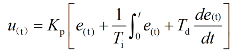
In the formula: e (t) is the control deviation; Kp is the proportional coefficient; Ti is the integration time constant; Td is the differential time constant; U (t) is a linear combination of output and deviation PID. From the formula, it can be seen that using PID control has a good control effect on the interference generated during the temperature control process.
The microcontroller of the street light controller is selected as C8150F320, and reasonable charging is achieved by changing the duty cycle. The charging voltage required to convert solar energy into lead-acid batteries also requires a DC/DC converter, so MAX668 converter is chosen. The temperature sensor DS18B20 is selected to collect temperature and observe whether it exceeds the set value. A control system with a microcontroller as the control core, based on the collected information, decides whether to use MPPT charging or PID temperature control charging to achieve intelligent charging with temperature protection.
2. Software design with temperature protection
The system detects the charging voltage U, charging current I, and temperature T of the controller chip in real-time. If the temperature T of the controller chip exceeds the set temperature TC, the PID temperature control mode is activated for charging. Otherwise, the MPPT mode is used for charging. When using PID temperature control for charging, the system outputs an appropriate duty cycle D to reduce output power and lower temperature. When the temperature drops to the set lower limit, the MPPT charging method is activated. When conducting MPPT charging, the system detects whether the charging current I is less than the acceptable charging current IC of the current battery. If I is less than IC, start the MPPT charging method with disturbance observation method. Otherwise, use IC charging. Therefore, by adopting a temperature protection charging method, the temperature of the system can be effectively controlled, while improving the charging efficiency of the control system and extending its service life.
3. Simulation
Choose a day in summer for simulation, use MATLAB/Simulink simulation software to build a simulation model, and obtain simulation results. A simulation comparison was made between the MPPT charging method without PID temperature protection and the MPPT charging method with PID temperature protection. The results are shown in the figure. In the figure, P1 and TI represent the output power of the MPPT without PID temperature protection and the surface temperature of the controller chip, while P2 and T2 represent the output power of the MPPT with PID temperature protection and the surface temperature of the controller chip.
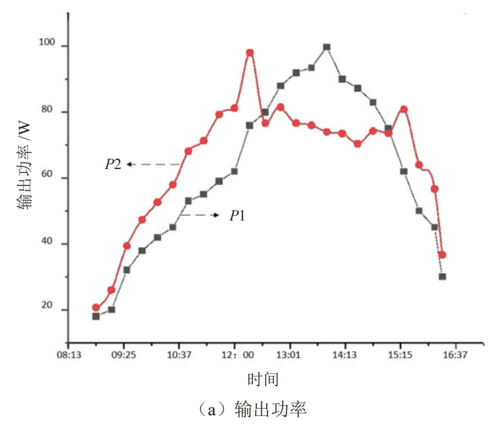
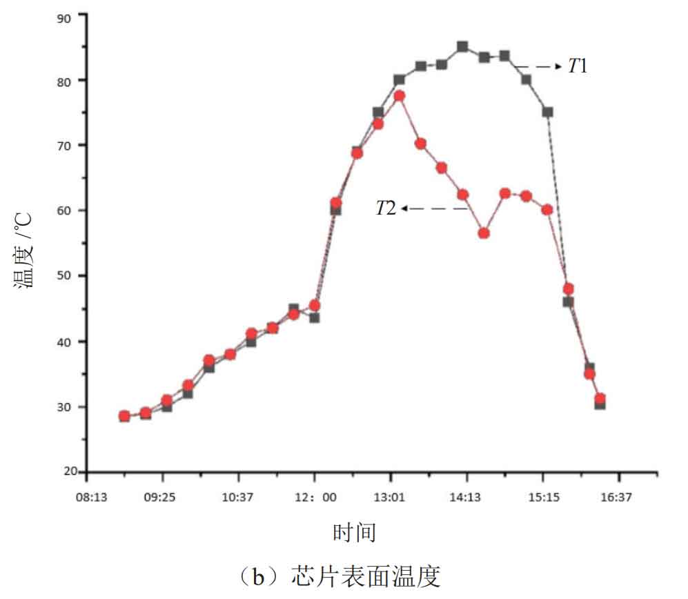
As shown in the figure, from 8:00 to 12:00, with the continuous increase of light intensity and temperature, the output power and chip temperature collected by the system also continue to increase. Subsequently, with the continuous increase of light intensity and surface temperature, the chip has reached a higher temperature. If MPPT charging is continued at this time, the power consumption of the chip will increase due to the need for MPPT, This will further exacerbate the heat generation of the chip. As shown in the figure, the temperature can reach 85 ℃, but the operating temperature range of the chip is generally 0-80 ℃. Prolonged high temperature will cause damage to the chip. The system adopts a charging method with PID temperature protection, and the MPPT charging method is initially started for charging. When the chip temperature is detected to rise to 70 ℃, PID temperature control is activated to form a dynamic balance between the output power of the solar cell and the surface temperature of the controller chip, At around 2:30 pm, due to the decrease in light intensity and temperature, the system activated MPPT charging again. The simulation results show that the intelligent control system that automatically adjusts the charging method based on temperature changes meets the design requirements.
4. Conclusion
In summary, the solar street light intelligent control system with temperature control effect can automatically adjust the charging method according to temperature changes. When the temperature exceeds the set temperature, the system adopts PID temperature control charging, which can to some extent protect the service life of the DC/DC chip hardware and extend the service cycle of the street light; When the temperature returns to normal, start the MPPT charging method to effectively protect the lifespan of the chip and reduce the frequency of replacing street light equipment.