
The integration of renewable energy sources, particularly photovoltaic (PV) generation, has become a cornerstone of modern power systems. The grid connected inverter serves as the critical interface between the PV array and the utility grid, responsible for converting DC power to AC power and ensuring its compliant injection. However, the power electronic switching inherent to these inverters introduces current harmonics and disturbances into the grid. Furthermore, the proliferation of non-linear loads within the distribution network exacerbates harmonic pollution. These harmonics degrade power quality, leading to equipment malfunction, increased losses, and potential stability concerns. Therefore, effective harmonic suppression at the point of common coupling (PCC) is paramount for the reliable and high-quality operation of power systems with high penetration of distributed generation.
Traditional approaches to harmonic mitigation often involve passive filters or dedicated active power filters (APFs). While passive LC or LCL filters attached to the grid connected inverter output are common, they can be bulky and offer limited flexibility in targeting specific harmonic orders. Dedicated APFs, though highly effective and responsive, represent an additional capital and operational cost, effectively duplicating power converter hardware. This reality motivates the exploration of multifunctional grid connected inverters—systems that not only deliver active power but also actively participate in grid support services like harmonic compensation. By repurposing the existing inverter’s control degrees of freedom, we can enhance power quality without significant additional hardware, improving the utilization and economic value of the PV installation.
In this context, the choice of output filter for the grid connected inverter is crucial. The LCL filter is a standard choice due to its superior high-frequency attenuation compared to a simple L filter. However, to achieve sufficient attenuation at the switching frequency, the total inductance of an LCL filter can still be substantial, impacting the system’s dynamic response and physical size. A more advanced topology, the Inductor-Inductor-Capacitor-Inductor (LLCL) filter, offers a compelling alternative. By replacing the capacitor branch in an LCL filter with a series LC resonant trap tuned to the switching frequency, the LLCL filter provides a very high impedance at a specific harmonic frequency (e.g., the switching frequency), allowing for significantly reduced inductance values while maintaining excellent filtering performance. This characteristic makes the LLCL filter an ideal candidate for compact and efficient grid connected inverter designs.
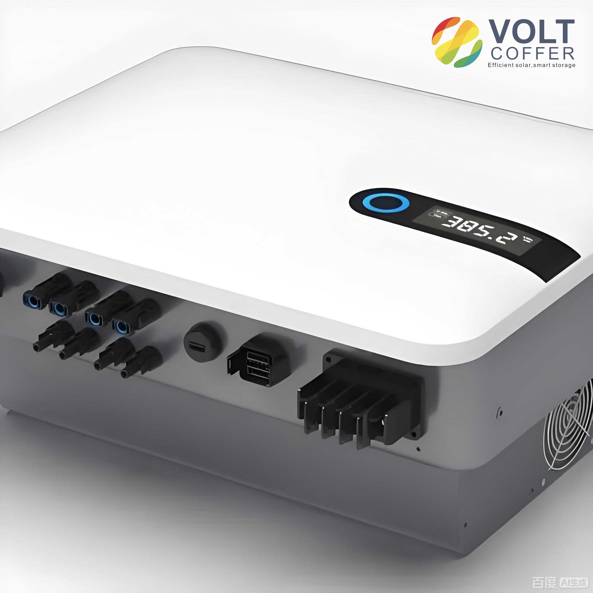
This article presents a comprehensive study on a multifunctional control strategy for a three-phase PV grid connected inverter employing an LLCL filter. The primary objective is for the inverter to perform dual functions: (1) inject fundamental active power from the PV array with high quality, and (2) actively compensate for selected low-order harmonic currents present at the PCC, thereby improving the overall grid current waveform. We will delve into the system topology, derive the mathematical model of the LLCL filter, establish a systematic parameter design methodology, and detail the proposed multi-loop control strategy. Finally, simulation results will be provided to validate the effectiveness of the approach in both linear and non-linear load scenarios.
System Topology and LLCL Filter Modeling
The topology of the three-phase two-level voltage source converter (VSC) acting as the PV grid connected inverter is shown in the figure. It consists of the PV array (represented by a DC voltage source U_dc), a DC-link capacitor C_dc, the VSC bridge, the LLCL filter, and the grid connection point. The LLCL filter components per phase are: the inverter-side inductor L_1, the grid-side inductor L_2, and the resonant trap branch comprising inductor L_f and capacitor C_f in series. The grid is represented by its voltage u_g and a series impedance Z_g. The key currents are the inverter output current i_inv, the current through the trap branch i_c, and the grid current i_g. The voltages at the inverter output and the PCC are u_inv and u_pcc, respectively.
To design the controller and analyze stability, an accurate model of the LLCL filter is essential. Applying Kirchhoff’s voltage and current laws to the per-phase equivalent circuit allows us to derive the transfer functions from the inverter output voltage u_inv to the inverter-side current i_inv and to the grid current i_g. These transfer functions describe the frequency-domain behavior of the grid connected inverter’s output stage.
The transfer function from u_inv to i_inv is given by:
$$ G_{i\_inv}(s) = \frac{I_{inv}(s)}{U_{inv}(s)} = \frac{L_2 C_f s^2 + 1}{[L_1 L_2 C_f + (L_1 + L_2)L_f C_f]s^3 + (L_1 + L_2)s} $$
Similarly, the transfer function from u_inv to i_g is:
$$ G_{i\_g}(s) = \frac{I_g(s)}{U_{inv}(s)} = \frac{L_f C_f s^2 + 1}{[L_1 L_2 C_f + (L_1 + L_2)L_f C_f]s^3 + (L_1 + L_2)s} $$
The denominator of both transfer functions reveals a third-order system. The numerator of G_{i_g}(s) contains a pair of imaginary zeros at the resonant frequency of the trap branch, \omega_{trap} = 1/\sqrt{L_f C_f}. When this trap frequency is tuned to the dominant switching harmonic (e.g., the switching frequency f_{sw}), the transfer function gain at that frequency is drastically reduced, leading to excellent attenuation of the switching ripple in the grid current. This is the key advantage of the LLCL filter over the standard LCL type for a grid connected inverter, as it allows for smaller values of L_1 and L_2 to meet the same grid current ripple standards.
LLCL Filter Parameter Design Methodology
The performance of the grid connected inverter is highly sensitive to the LLCL filter parameters. A systematic design procedure must consider multiple constraints related to current ripple, voltage drop, reactive power, and stability. The following constraints guide the parameter selection for a grid connected inverter with a specified power rating P_N, grid line voltage U_g, and fundamental frequency f_0.
| Constraint Category | Design Rule | Mathematical Expression |
|---|---|---|
| Inverter Current Ripple | The peak-to-peak ripple on the inverter-side inductor current should be limited to a percentage of the rated current. | $$ \Delta I_{r1} = (10\% \text{ to } 30\%) \cdot I_N $$ where $$ I_N = \frac{P_N}{\sqrt{3} U_g} $$ |
| Grid Current Ripple | The high-frequency ripple (e.g., around 2f_{sw}) in the grid current must comply with standards (e.g., <0.3% of I_N). This is primarily governed by the trap attenuation. |
$$ |G_{i_g}(j2\pi \cdot 2f_{sw})| \cdot \Delta U_{ripple} < 0.003 \cdot I_N $$ |
| Total Inductor Voltage Drop | The fundamental-frequency voltage drop across the total inductance should not exceed a fraction of the grid voltage to avoid deep modulation. | $$ \omega_0 (L_1 + L_2) \cdot I_N < 10\% \cdot U_{g,phase} $$ where $$ \omega_0 = 2\pi f_0 $$ |
| Reactive Power from Capacitor | The reactive power generated by the filter capacitor at the fundamental frequency should be limited. | $$ Q_{C_f} = 3 \cdot \omega_0 C_f U_{g,phase}^2 < 5\% \cdot P_N $$ |
| Trap Frequency Tuning | The series resonant frequency of the trap branch is set to the main switching frequency to maximize attenuation. | $$ \omega_{trap} = 2\pi f_{sw} = \frac{1}{\sqrt{L_f C_f}} $$ |
| Resonant Frequency Placement | The inherent resonant frequency of the LLCL filter must be placed appropriately for controller stability. | $$ 10 f_0 < f_{res} < 0.5 f_{sw} $$ where $$ f_{res} = \frac{1}{2\pi} \sqrt{\frac{L_1 + L_2}{L_1 L_2 C_f + (L_1+L_2)L_f C_f}} $$ |
| Trap Branch Quality Factor | A small damping resistor R_f (not shown in the basic topology) may be added in series with L_f and C_f to damp the trap and prevent excessive gain at f_{trap}. |
$$ Q = \frac{1}{R_f} \sqrt{\frac{L_f}{C_f}} $$ (Typically chosen to be moderate, e.g., 5-10) |
By simultaneously solving these constraints for a given system specification, a viable set of parameters for the grid connected inverter’s LLCL filter can be determined. For instance, for a 32 kW, 380 V system with a 5 kHz switching frequency, a typical parameter set derived from these rules could be: L_1 = 1.2 mH, L_2 = 0.2 mH, L_f = 6 \mu H, C_f = 32 \mu F. The Bode plot of the grid current transfer function G_{i_g}(s) with these parameters would show a pronounced notch at 5 kHz, demonstrating the filter’s effectiveness for this grid connected inverter application.
Proposed Multifunctional Control Strategy
The core innovation of this work lies in the control strategy that enables the single grid connected inverter to perform dual tasks. The overall control block diagram is implemented in the synchronous (dq) reference frame. The strategy comprises four main modules: DC-Link Voltage Control, Fundamental Current Control, Harmonic Current Detection, and Harmonic Current Compensation.
DC-Link Voltage Control: This outer loop ensures stable DC-bus voltage, which is essential for extracting maximum power from the PV array. The measured DC voltage U_{dc} is compared to its reference U_{dc}^*. The error is processed by a PI controller to generate the reference for the active (d-axis) component of the fundamental grid current, i_{d,f}^*. The q-axis reference i_{q,f}^* is typically set to zero for unity power factor operation or can be set to a non-zero value for reactive power support. The control law can be expressed as:
$$ i_{d,f}^* = \left( K_{p,dc} + \frac{K_{i,dc}}{s} \right) (U_{dc}^* – U_{dc}) $$
This module ensures that the grid connected inverter regulates its power output to balance the PV generation.
Harmonic Current Detection: To compensate for harmonics, they must first be accurately detected. This is achieved using the Instantaneous Power Theory (p-q theory) in the time domain. The three-phase grid currents i_{g,abc} are transformed into the synchronous dq0 frame using the grid voltage phase angle \theta obtained from a Phase-Locked Loop (PLL). In this rotating frame, fundamental positive-sequence components appear as DC quantities, while harmonic components appear as AC quantities at frequencies shifted by the fundamental. Low-Pass Filters (LPFs) are used to extract the DC components (i_{gd0}, i_{gq0}), which represent the fundamental current. These are then transformed back to the abc frame to obtain the fundamental current waveform i_{g,abc}^f. The harmonic current is obtained by subtraction:
$$ i_{g,abc}^h = i_{g,abc} – i_{g,abc}^f $$
For targeting specific orders (like the 5th and 7th), multiple synchronous reference frames (MSRF) or band-pass filters tuned to the specific frequencies in the dq frame can be used to extract i_{d,k}^h and i_{q,k}^h for the k-th harmonic order.
Fundamental and Harmonic Current Control: The current control is split into parallel paths. The fundamental current control loop takes the references i_{d,f}^*, i_{q,f}^* and the measured fundamental components i_{d,f}, i_{q,f} (obtained from the detection block or via separate filtering). A standard PI controller in the dq frame is used, augmented with cross-coupling and grid voltage feedforward terms for decoupling and disturbance rejection. The output is the fundamental component of the modulation signal, v_{m,f}^*.
$$ v_{md,f}^* = \left( K_{p,f} + \frac{K_{i,f}}{s} \right)(i_{d,f}^* – i_{d,f}) – \omega L_{eq} i_{q,f} + \hat{u}_{gd} $$
$$ v_{mq,f}^* = \left( K_{p,f} + \frac{K_{i,f}}{s} \right)(i_{q,f}^* – i_{q,f}) + \omega L_{eq} i_{d,f} + \hat{u}_{gq} $$
Here, L_{eq} is an equivalent inductance used for decoupling, and \hat{u}_{gd}, \hat{u}_{gq} are the estimated grid voltage components.
The harmonic compensation loop works on the same principle but for specific harmonic frequencies. The reference for the harmonic compensator is zero, as the goal is to cancel the detected harmonic currents. For the k-th harmonic, resonant controllers or PI controllers within multiple rotating frames are highly effective. A Proportional-Resonant (PR) controller in the stationary frame offers a simpler alternative, providing high gain at a specific frequency \omega_k = k \cdot \omega_0. The harmonic modulation signal v_{m,k}^* is generated by:
$$ v_{m,\alpha\beta,k}^* = \sum_{k} \left( K_{p,h} + \frac{2 K_{i,h} s}{s^2 + \omega_k^2} \right) (0 – i_{\alpha\beta,k}^h) $$
where the sum is over the harmonic orders to be compensated (e.g., 5, 7, 11, 13).
The final modulation signal for the grid connected inverter is the sum of the fundamental and all harmonic compensation signals:
$$ v_{m,\alpha\beta}^* = v_{m,\alpha\beta,f}^* + \sum_{k} v_{m,\alpha\beta,k}^* $$
This composite signal is then fed to the PWM generator to produce the switching signals for the VSC bridges. This integrated control allows a single grid connected inverter to inject clean active power while simultaneously acting as an active power filter for the local network.
Simulation Analysis and Validation
To validate the proposed multifunctional control strategy for the LLCL-type grid connected inverter, a detailed simulation model was built in MATLAB/Simulink. The system parameters are summarized in the table below:
| Parameter | Symbol | Value |
|---|---|---|
| Rated Power | P_N |
32 kW |
| DC-Link Voltage | U_{dc} |
700 V |
| Grid Line Voltage | U_g |
380 V (RMS), 50 Hz |
| Switching Frequency | f_{sw} |
5 kHz |
| LLCL Filter: Inverter-side Inductor | L_1 |
1.2 mH |
| LLCL Filter: Grid-side Inductor | L_2 |
0.2 mH |
| LLCL Filter: Trap Inductor | L_f |
6 μH |
| LLCL Filter: Trap Capacitor | C_f |
32 μF |
| DC-Link Capacitor | C_{dc} |
3 mF |
Two distinct test scenarios were evaluated: one with a linear (RL) load and one with a non-linear (diode rectifier) load connected at the PCC, drawing power from both the grid and the PV grid connected inverter.
Scenario 1: Operation with Linear Load
In this case, the background harmonic distortion is low. Initially, the grid connected inverter operates only in active power injection mode (harmonic compensation disabled). At t = 0.2 s, the harmonic compensation function is activated. The grid current waveforms show minimal visual change because the load itself produces few harmonics. However, quantitative analysis through Total Harmonic Distortion (THD) measurement reveals the impact. The THD of the grid current (source side) decreased from 6.63% to 1.92% after enabling compensation. This demonstrates that even under relatively clean conditions, the control strategy of the multifunctional grid connected inverter further purifies the grid current by compensating for the small harmonics generated by the inverter’s own switching and any minor background distortion.
Scenario 2: Operation with Non-linear Load
This scenario presents a more challenging and realistic test. A three-phase diode rectifier with a DC-side RC load is connected, generating significant 5th, 7th, 11th, and 13th harmonic currents. Initially, with only power injection active, the grid current is highly distorted due to the rectifier load. The measured THD is 23.7%. At t = 0.2 s, the harmonic compensation loops (tuned for these specific orders) are activated. The response is rapid. The grid current waveform transforms into a nearly sinusoidal shape. The multifunctional grid connected inverter is now successfully supplying a portion of the load’s fundamental current and all of its harmonic current, preventing it from flowing into the grid. The post-compensation THD is reduced to 4.2%, which is well within typical harmonic standards like IEEE 519. Crucially, the fundamental component of the current from the grid connected inverter remains stable, confirming that the power injection function is not compromised by the harmonic compensation activity.
| Scenario | Condition | Grid Current THD | Key Observation |
|---|---|---|---|
| Linear Load | Before Compensation | 6.63% | Inherent distortion from inverter switching and minor grid background. |
| After Compensation | 1.92% | The multifunctional grid connected inverter actively cleans its own output and local grid current. | |
| Non-linear Load | Before Compensation | 23.7% | Severe distortion due to rectifier load harmonics flowing into the grid. |
| After Compensation | 4.2% | The grid connected inverter successfully provides harmonic current, dramatically improving grid power quality while maintaining active power flow. |
The simulation results conclusively validate the proposed approach. The LLCL filter, with its reduced inductance, enables a compact design for the grid connected inverter without sacrificing high-frequency filtering performance. The integrated multi-loop control strategy effectively decouples the fundamental power control and harmonic compensation tasks, allowing a single power converter to perform both functions seamlessly. This transforms the standard PV grid connected inverter from a mere power source into an active power quality conditioner, enhancing its value and utility in the modern power grid.
Conclusion
This research has presented a comprehensive solution for enhancing the functionality of a photovoltaic grid connected inverter. By employing an advanced LLCL output filter and a sophisticated multifunctional control strategy, the system achieves two primary objectives: high-efficiency injection of solar power and active mitigation of grid current harmonics. The LLCL filter’s design, with its series resonant trap, allows for a significant reduction in the required filter inductance compared to traditional LCL designs. This leads to a more compact, cost-effective, and dynamically faster grid connected inverter system. The systematic parameter design methodology ensures stable and optimal filter performance.
The proposed control architecture is the cornerstone of the multifunctional capability. It seamlessly integrates DC-link voltage regulation (for maximum power point tracking and DC-bus stability), fundamental current control (for active/reactive power delivery), and selective harmonic current compensation. The use of resonant or multi-frame PI controllers for harmonic compensation provides the necessary high gain at selected frequencies to force the grid connected inverter to generate opposing harmonic currents, thereby canceling those present at the PCC. Simulation studies under both linear and non-linear load conditions have demonstrated the strategy’s outstanding effectiveness. The grid connected inverter successfully maintained stable active power output while reducing grid current THD from over 23% to below 5% in a demanding non-linear load scenario.
In conclusion, this work demonstrates that through intelligent filter design and control, a standard PV grid connected inverter can be upgraded to a multifunctional device that actively contributes to power quality improvement. This approach maximizes the utilization of power electronics infrastructure, potentially reducing or eliminating the need for separate harmonic mitigation devices. It represents a significant step towards smarter, more responsive, and more valuable distributed energy resources in future power networks. Future work may involve experimental validation on a hardware prototype, investigation of stability under weak grid conditions, and expansion of the control strategy to include unbalanced load compensation and other grid-supportive functions.