
As a researcher in mechanical engineering, I have dedicated my recent work to investigating the dust accumulation behavior on solar panels and developing an efficient anhydrous cleaning device. In this paper, I present a comprehensive study that combines theoretical mechanics, structural design, finite element analysis, and experimental optimization. The objective is to provide a practical solution for maintaining the power generation efficiency of photovoltaic systems in arid and dusty environments where water resources are scarce. Throughout this work, I focus on solar panels arranged in two-row spliced arrays, which are common in large-scale photovoltaic plants. I establish a mechanical model for dust particles, design a novel cleaning device, verify its performance through simulation, and optimize its operating parameters through controlled experiments. The final optimized cleaning rate reaches 97.38%, demonstrating the effectiveness of the proposed approach.
1. Introduction
The global demand for renewable energy has accelerated the deployment of solar power plants. Solar panels, as the core components of photovoltaic systems, convert sunlight into electricity. However, their performance is significantly affected by the accumulation of dust and particulate matter on the surface. Dust particles block incident sunlight, reduce the effective receiving area, and increase the surface temperature, which can lead to hot spots and even permanent damage. In many regions where solar panels are installed, the climate is characterized by high temperatures, low rainfall, and frequent dust storms. Therefore, regular cleaning is essential to maintain high efficiency and prolong the service life of solar panels.
Conventional cleaning methods include manual wiping, high-pressure water washing, and large cleaning vehicles. These approaches often require substantial labor or water resources, making them unsuitable for remote arid areas. In recent years, several automated cleaning robots have been developed, but many of them are expensive, have limited reliability, or require complex infrastructure. To address these challenges, I have designed a lightweight, low-cost, and reliable anhydrous cleaning device specifically for solar panels arranged in two-row spliced arrays. The device uses a rotating brush driven by a DC motor and moves along the panel frame using a chain transmission system. It is powered by an onboard photovoltaic module and a lithium battery pack, allowing self-sustained operation without external power or water.
This paper is organized as follows. First, I analyze the adhesion mechanism of dust particles on solar panels from energy and force perspectives, and establish a mechanical model to calculate the required cleaning force. Then, I describe the overall structural design of the cleaning device, including the cleaning system, walking system, and limiting system. Next, I present finite element simulations to verify the cleaning force, structural stiffness, and strength of key components. A response surface methodology is used for lightweight optimization of the drive shaft. Finally, I conduct field experiments to investigate the effects of brush rotational speed and translational speed on the cleaning rate, build a mathematical model, and use MATLAB to find optimal working parameters.
2. Dust Particle Adhesion and Mechanical Modeling
2.1 Adhesion Mechanism from an Energy Perspective
Every solid surface possesses residual free energy due to the difference between surface free energy and internal free energy. The specific excess free energy is given by:
$$ \Gamma = \frac{G_s}{A} – \frac{\mu_i n_s}{A} $$
where \(G_s\) is the surface free energy, \(A\) is the area, and \(\mu_i n_s\) represents the internal contribution. Materials with high surface free energy tend to attract substances with lower surface free energy to minimize the total energy. The glass surface of solar panels has a relatively high residual free energy, which explains why dust particles readily adhere to the panel surface. This energy analysis provides a fundamental understanding of the fouling phenomenon, but for engineering design, a force-based model is more practical.
2.2 Force Analysis of Dust Particles
Dust particles on solar panels are subjected to three main adhesion forces: van der Waals force, gravity, and electrostatic forces. The van der Waals force between a spherical particle and a plane surface can be expressed as:
$$ F_{vdw} = \frac{h r}{8 \pi Z^2} $$
where \(h\) is the Lifshitz–van der Waals constant (for silica systems, \(h = 2.09\) to \(2.91\) eV), \(r\) is the particle radius, and \(Z\) is the molecular separation distance. The molecular separation can be estimated from:
$$ Z = 2 \left( \frac{2 M}{3 N L \rho} \right)^{1/3} $$
where \(M\) is the relative molecular mass, \(N\) is Avogadro’s number, \(L\) is the number of atoms per molecule, and \(\rho\) is the particle density. For typical dust on solar panels, taking \(M = 60\), \(L = 3\), \(\rho = 2 \times 10^3 \, \text{kg/m}^3\), and \(N = 6.02 \times 10^{23}\), I obtained \(Z = 2.34 \times 10^{-8}\) m.
In my field measurements of dust particles on solar panels, the radius ranged from \(0.13 \times 10^{-6}\) m to \(60.6 \times 10^{-6}\) m, and more than 95% of the total volume consisted of particles with radius \(r \le 35 \times 10^{-6}\) m. To ensure the cleaning device can handle the worst-case scenario, I selected \(r = 35 \times 10^{-6}\) m for detailed calculation. Using \(h = 2.91 \, \text{eV}\) and \(Z = 2.34 \times 10^{-8}\) m, the van der Waals force becomes:
$$ F_{vdw} = \frac{2.91 \times 1.6 \times 10^{-19} \times 35 \times 10^{-6}}{8 \pi (2.34 \times 10^{-8})^2} = 3.39 \times 10^{-9} \, \text{N} $$
The gravitational force acting on a spherical particle is:
$$ G = m g = \frac{4}{3} \pi r^3 \rho g $$
Substituting \(\rho = 2 \times 10^3 \, \text{kg/m}^3\), \(g = 9.8 \, \text{m/s}^2\), and \(r = 35 \times 10^{-6}\) m:
$$ G = \frac{4}{3} \pi (35 \times 10^{-6})^3 \times 2 \times 10^3 \times 9.8 = 3.51 \times 10^{-9} \, \text{N} $$
Electrostatic forces include the Coulomb attractive force and the electric image force. For a charged particle near a conducting surface, the Coulomb force can be approximated by:
$$ F_{es} = \frac{\alpha Q_D^2}{16 \pi \varepsilon_0 r^2} $$
where \(\alpha = 1.9\), \(Q_D\) is the charge on the dust particle, \(\varepsilon_0 = 8.85 \times 10^{-12} \, \text{F/m}\), and \(r\) is the particle radius. For a particle with radius \(35 \times 10^{-6}\) m, the typical charge is about \(3.36 \times 10^{-14}\) C, giving:
$$ F_{es} = \frac{1.9 (3.36 \times 10^{-14})^2}{16 \pi (8.85 \times 10^{-12})(35 \times 10^{-6})^2} = 3.94 \times 10^{-9} \, \text{N} $$
Another electrostatic component arises from the contact potential difference \(U\) between the particle and the panel surface:
$$ F_{et} = \frac{\pi \varepsilon_0 U r}{r + Z} $$
With \(U = 0.5\) V and \(r = 35 \times 10^{-6}\) m, this yields \(F_{et} = 6.94 \times 10^{-12}\) N, which is two orders of magnitude smaller than the van der Waals and gravity forces.
2.3 Mechanical Model and Resultant Force
To determine the minimum cleaning force required, I established a force balance in the direction perpendicular to the solar panel surface. The resultant adhesion force \(F_y\) is:
$$ F_y = T_y + F_{es} + F_{et} + G_y + F_{vdw} $$
where \(T_y\) represents the contribution of inter-particle forces (which is complex and often neglected in first-order estimation), \(G_y = G \cos \theta\) is the gravity component normal to the panel surface, and \(\theta\) is the tilt angle of the solar panels. For a typical tilt angle of \(40^\circ\), the resultant force is at least:
$$ F_y = 3.94 \times 10^{-9} + 6.94 \times 10^{-12} + 3.51 \times 10^{-9} \cos 40^\circ + 3.39 \times 10^{-9} = 1.00 \times 10^{-8} \, \text{N} $$
This value is on the order of \(10^{-8}\) N. It is important to note that the inter-particle forces may increase the actual adhesion force, so the cleaning force should be designed with a substantial safety margin. My mechanical model was validated by comparing with published atomic force microscopy measurements of micron-sized particles, which reported adhesion forces on the order of \(10^{-8}\) N for similar radius ranges. This agreement confirms the reasonableness of the model.
| Force component | Symbol | Magnitude (N) | Order of magnitude |
|---|---|---|---|
| Van der Waals force | \(F_{vdw}\) | \(3.39 \times 10^{-9}\) | \(10^{-9}\) |
| Gravity (normal component at 40°) | \(G_y\) | \(2.69 \times 10^{-9}\) | \(10^{-9}\) |
| Coulomb electrostatic force | \(F_{es}\) | \(3.94 \times 10^{-9}\) | \(10^{-9}\) |
| Contact potential static force | \(F_{et}\) | \(6.94 \times 10^{-12}\) | \(10^{-12}\) |
| Minimum resultant adhesion force | \(F_y\) | \(1.00 \times 10^{-8}\) | \(10^{-8}\) |
3. Structural Design of the Anhydrous Cleaning Device
3.1 Design Requirements
The cleaning device must meet several design constraints to be practical for real solar panel installations:
- It must perform dry cleaning without any water, because most solar power plants are located in arid regions.
- It must operate on inclined solar panels (tilt angle typically 0°–60°) without sliding off.
- It should be able to traverse the gaps and height differences between adjacent panels.
- The walking wheels should run on the aluminum frame of the panels, not directly on the glass surface, to avoid damage.
- The translational speed should be adjustable between 12 and 40 m/min, and the brush rotational speed between 70 and 120 rpm.
- The device should be lightweight, low-cost, reliable, and easy to maintain.
3.2 Overall Layout
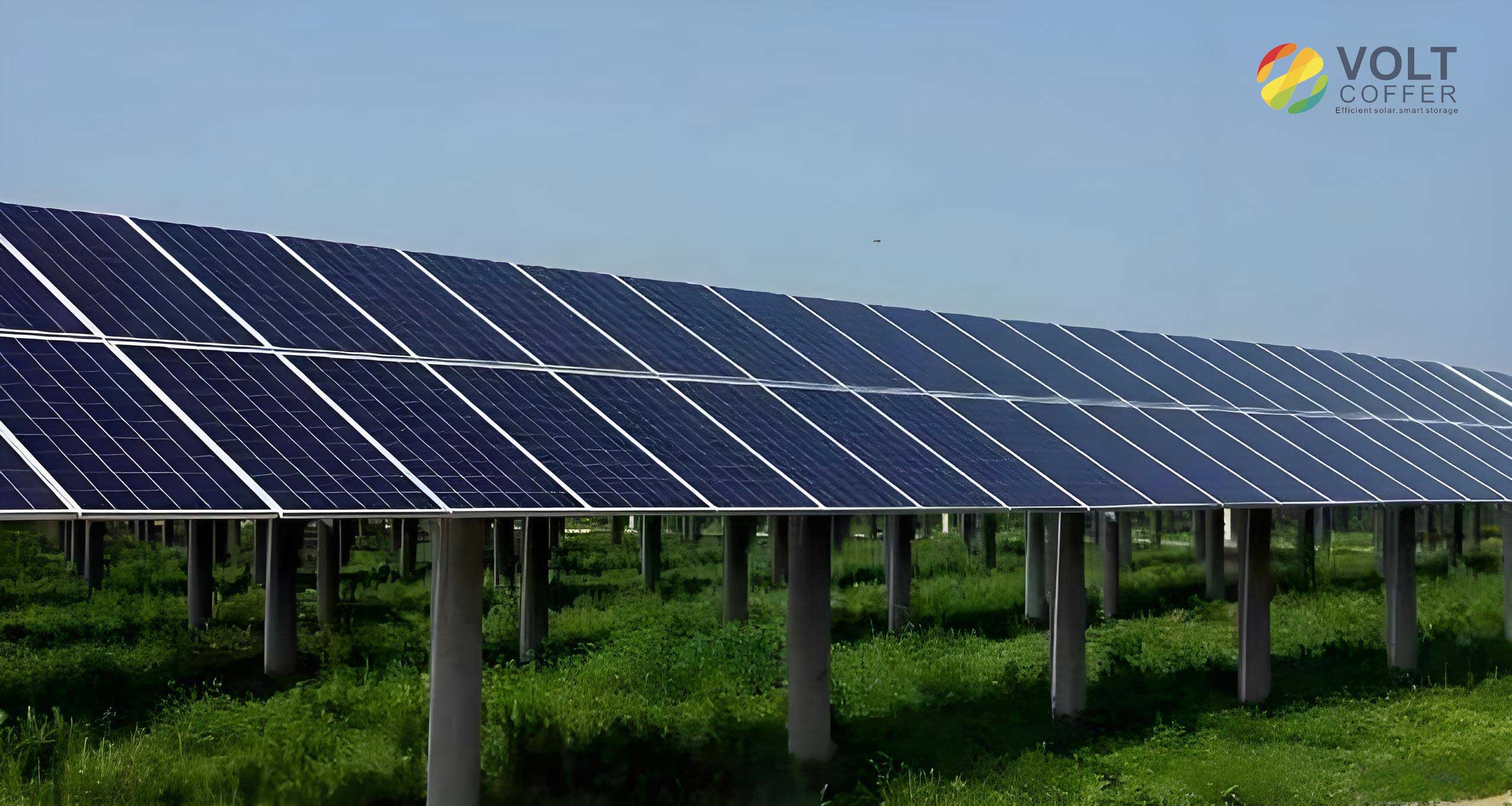
The device consists of a cleaning system, a walking system, a limiting system, an onboard photovoltaic module, a lithium battery pack, and a housing. The solar panels are arranged in two-row spliced arrays. On the left side of each row, a turning bracket is installed, and on the right side, a parking rack is provided. Adjacent columns of panels are connected by bridging plates. The cleaning device moves back and forth along the panel rows. Limit switches and self-locking mechanisms ensure safe operation and prevent the device from falling off during strong winds.
3.3 Cleaning System
The cleaning system uses a rotating brush to dislodge dust particles. Among the three common cleaning mechanisms — lifting, sliding, and rolling — the rolling mechanism is most suitable for dry brushing. The brush consists of a PPR inner tube and an aluminum alloy outer tube. Nylon PA6 bristles are implanted helically on the outer surface. The total diameter of the brush including bristles is 150 mm, and the brush length is 1647 mm. The bristle diameter is 0.2 mm, with an extended length of 54 mm. Two brushes are connected in tandem and driven by a DC gear motor through a chain drive. The cleaning motor is a Z3D40-12GN-18S DC gear motor with 40 W power, 12 V voltage, 96 rpm output speed, and 2.9 N·m torque.
For motor selection, I estimated the required torque by assuming a contact force of 20 N between bristles and panel, friction coefficient 0.5, and brush diameter 0.15 m. The friction force is \(F_f = 10\) N, and the torque is \(T = 10 \times 0.075 = 0.75 \, \text{N·m}\). With a safety factor of 3, the required motor torque is 2.25 N·m. The selected motor provides 2.9 N·m, which is adequate.
3.4 Walking System
The walking system consists of a motor, chain drive, drive shafts, universal joints, and walking wheels. The motor is a 5IK40RGN-C DC gear motor with 40 W power, 12 V voltage, 36 rpm speed, and 7.7 N·m torque. The walking wheels have a diameter of 120 mm and are made of cast aluminum hubs with rubber treads for better grip. Each wheel is mounted on a shaft with deep groove ball bearings (SF6803Z). The transmission uses roller chains for reliability in outdoor environments. The walking system is designed with three rows of wheels (upper, middle, lower) to distribute the load and prevent the device from tipping over. The total mass of the device is approximately 32 kg.
| Component | Specification | Material / Model |
|---|---|---|
| Cleaning motor | 40 W, 12 V, 96 rpm, 2.9 N·m | Z3D40-12GN-18S |
| Walking motor | 40 W, 12 V, 36 rpm, 7.7 N·m | 5IK40RGN-C |
| Roller brush diameter | 150 mm (with bristles) | PPR + aluminum + PA6 |
| Bristle material | Nylon PA6, 0.2 mm diameter | PA6 |
| Walking wheel diameter | 120 mm | Cast aluminum + rubber |
| Drive shaft diameter | 16 mm (after optimization) | 45 steel |
| Power source | 12 V lithium battery pack | 40°C–70°C |
3.5 Limiting System
To prevent the cleaning device from sliding off the inclined solar panels, both upper and lower limiting systems are installed. The limiting wheels are similar to walking wheels but smaller, and they are attached to welded plates via bolts. The upper limiting wheels bear the component of gravity along the panel surface. In my design, the upper limiting system was simulated to ensure sufficient strength and stiffness.
4. Finite Element Analysis and Structural Optimization
4.1 Simulation Setup
I used ANSYS Workbench to perform static structural analyses. The three-dimensional models were created in NX 10.0 and imported into the simulation environment. The material properties assigned to the components are summarized in Table 3.
| Material | Density (kg/m³) | Young’s Modulus (GPa) | Poisson’s Ratio |
|---|---|---|---|
| Aluminum Alloy | 2770 | 71 | 0.33 |
| PA6 | 1130 | 2.32 | 0.34 |
| 45 steel | 7850 | 210 | 0.31 |
4.2 Cleaning Force Simulation
To verify that the brush can generate sufficient cleaning force, I performed a nonlinear contact simulation of the brush bristles. The brush model was simplified, and the bristles were bonded to the brush core. A fixed constraint was applied to the brush shaft, and a displacement of 5.0375 mm was imposed on the bristle tips in the tangential direction. The reaction force was then extracted as the cleaning force.
The simulation results showed that the maximum deformation of the brush shaft was 0.13145 mm, and the maximum stress was 101.86 MPa, which are acceptable for the aluminum alloy shaft. The tangential deflection of the bristle tips was 5.0375 mm. The reaction force obtained from the simulation was 0.81936 N. This value is about eight orders of magnitude larger than the adhesion force of dust particles calculated earlier (\(1.0 \times 10^{-8}\) N). Even considering additional contamination such as sand, bird droppings, and oil stains, the cleaning force is sufficient to remove the surface pollutants effectively.
4.3 Upper Limiting System Simulation
I modeled the upper limiting system and applied a force of 160 N on each limiting wheel in the normal direction, representing the component of the device’s weight (32 kg × 9.8 m/s² × sin 40° ≈ 205.7 N divided between two wheels). The simulation results are summarized in Table 4.
| Parameter | Result | Acceptance |
|---|---|---|
| Maximum deformation | 0.02802 mm | Stiffness sufficient |
| Maximum stress | 19.725 MPa | Strength sufficient |
The maximum deformation occurred at the edge of the limiting wheel, and the maximum stress occurred at the bolt. Both values are well below the yield strength of the material, confirming that the device will not slide off the solar panels under normal operating conditions.
4.4 Walking System Simulation and Design Comparison
I initially designed the walking system with two rows of wheels (upper and lower). The simulation showed a maximum deformation of 2.2314 mm at the coupling and a maximum stress of 74.987 MPa. Although the stress was acceptable, the deformation could cause synchronization issues. Therefore, I redesigned the system with three rows of wheels (upper, middle, lower). The improved design reduced the maximum deformation to 1.9861 mm, a reduction of about 11%, while the maximum stress increased slightly to 100.25 MPa but remained within safe limits. The three-row configuration provides better load distribution and prevents the device from getting stuck.
| Configuration | Max deformation (mm) | Max stress (MPa) |
|---|---|---|
| Two rows | 2.2314 | 74.987 |
| Three rows | 1.9861 | 100.25 |
4.5 Lightweight Design of the Drive Shaft Using Response Surface Methodology
The drive shaft in the walking system is a critical transmission component. A heavy shaft increases the overall weight of the device, which could damage the solar panels. To minimize mass while maintaining sufficient strength and stiffness, I used the response surface method combined with a multi-objective genetic algorithm (MOGA). The design variables were the inner diameter \(d\) and outer diameter \(D\) of the hollow shaft. The constraints were \(8 \le d \le 12\) mm and \(14 \le D \le 18\) mm. The response surface was generated using Kriging interpolation based on optimal space-filling design points.
The optimization problem was formulated as:
$$ \text{Minimize: Mass, Total Deformation, Equivalent Stress} $$
$$ \text{Subject to: } 8 \le d \le 12, \quad 14 \le D \le 18 $$
After optimization, the maximum deformation was 0.55168 mm, the maximum stress was 18.213 MPa, and the mass was 0.47316 kg. Compared with the initial design, the mass was reduced by 40.84%. This significant reduction helps protect the solar panels from excessive mechanical loading.
5. Experimental Study and Parameter Optimization
5.1 Experimental Setup and Procedure
To evaluate the actual cleaning performance of the device, I conducted field experiments on a solar panel installation at a photovoltaic park. The test dust was collected from real solar panels and included fine particles, sand, and other contaminants. In each test, 25 g of dust was uniformly spread over the panel surface. The device was then operated for one pass, and the residual dust was collected and weighed. The cleaning rate \(\eta\) was calculated as:
$$ \eta = \frac{A – B}{A} \times 100\% $$
where \(A\) is the initial dust mass (25 g) and \(B\) is the residual dust mass.
I used a control variable approach. The brush rotational speed was varied from 70 to 120 rpm in steps of 10 rpm, and the translational speed was varied from 0.2 to 0.7 m/s in steps of 0.1 m/s. This resulted in 36 different combinations. Each combination was tested five times, and the average residual mass was recorded.
5.2 Experimental Results
The average residual dust masses for all test conditions are shown in Table 6.
| Brush speed (rpm) | Translational speed (m/s) | |||||
|---|---|---|---|---|---|---|
| 0.2 | 0.3 | 0.4 | 0.5 | 0.6 | 0.7 | |
| 70 | 2.03 | 2.46 | 2.98 | 3.35 | 3.88 | 4.34 |
| 80 | 1.58 | 2.02 | 2.55 | 2.93 | 3.44 | 3.93 |
| 90 | 1.02 | 1.49 | 2.03 | 2.41 | 2.91 | 3.41 |
| 100 | 0.68 | 1.16 | 1.66 | 2.12 | 2.60 | 3.12 |
| 110 | 0.705 | 1.15 | 1.675 | 1.71 | 2.26 | 2.80 |
| 120 | 0.70 | 1.13 | 1.67 | 2.09 | 2.64 | 3.16 |
From these data, I calculated the cleaning rates, which are presented in Table 7.
| Brush speed (rpm) | Translational speed (m/s) | |||||
|---|---|---|---|---|---|---|
| 0.2 | 0.3 | 0.4 | 0.5 | 0.6 | 0.7 | |
| 70 | 91.88 | 90.16 | 88.08 | 86.60 | 84.48 | 82.64 |
| 80 | 93.68 | 91.92 | 89.80 | 88.28 | 86.24 | 84.28 |
| 90 | 95.92 | 94.04 | 91.88 | 90.36 | 88.36 | 86.36 |
| 100 | 97.28 | 95.36 | 93.36 | 91.52 | 89.60 | 87.52 |
| 110 | 97.18 | 95.40 | 93.30 | 92.11 | 90.96 | 88.80 |
| 120 | 97.20 | 95.48 | 93.32 | 91.64 | 89.44 | 87.36 |
Analysis of the data reveals that for a fixed brush speed, the cleaning rate decreases monotonically with increasing translational speed. For a fixed translational speed, the cleaning rate first increases with brush speed, reaches a maximum around 100–110 rpm, and then slightly decreases. This behavior can be attributed to the balance between the number of brush contacts and the centrifugal force acting on the bristles. At very high rotational speeds, the bristles may deflect excessively, reducing the effective contact force.
5.3 Regression Model
To quantitatively describe the relationship among cleaning rate \(y\), brush rotational speed \(x_1\) (rpm), and translational speed \(x_2\) (m/s), I proposed a quadratic regression model:
$$ y = \beta_0 + \beta_1 x_1 + \beta_2 x_1^2 + \beta_3 x_2 + \varepsilon $$
Using the least squares method with the experimental data, the fitted coefficients were obtained as:
$$ y = 0.610159 + 0.00714 x_1 – 0.0000318 x_1^2 – 0.1857 x_2 $$
The goodness-of-fit \(R^2\) was 0.991911, indicating an excellent fit. The \(t\)-values for the coefficients of \(x_1\) and \(x_2\) were 15.52 and -52.67, respectively, both exceeding the critical value \(t_{0.01}(33) = 2.74\), confirming that both parameters significantly affect the cleaning rate.
5.4 Optimization Using MATLAB
To maximize the cleaning rate, I formulated the following optimization problem:
$$ \max \quad y = 0.610159 + 0.00714 x_1 – 0.0000318 x_1^2 – 0.1857 x_2 $$
$$ \text{subject to } 70 \le x_1 \le 120,\quad 0.2 \le x_2 \le 0.7 $$
I solved this quadratic programming problem using MATLAB’s quadprog function. The optimal solution was \(x_1 = 112.2642\) rpm and \(x_2 = 0.2\) m/s. Substituting these values into the regression model gives the maximum cleaning rate:
$$ y_{\max} = 97.38\% $$
This optimized cleaning rate is higher than any of the experimentally measured values, which confirms the necessity and effectiveness of the optimization.
6. Conclusion
In this research, I have systematically analyzed the dust accumulation characteristics on solar panels and developed an anhydrous cleaning device capable of efficiently removing surface dust. The main conclusions are as follows:
- The adhesion force of dust particles on solar panels consists primarily of van der Waals forces, gravity, and electrostatic forces. For a representative particle radius of \(35 \times 10^{-6}\) m, the minimum resultant adhesion force perpendicular to the panel surface is \(1.0 \times 10^{-8}\) N. This value provides a theoretical basis for designing the cleaning force.
- The cleaning device was designed with a rotating brush cleaning system, a three-row walking system, and upper/lower limiting systems. Finite element analysis demonstrated that the brush can generate a cleaning force of 0.81936 N, which is sufficient to overcome the adhesion forces of dust particles. The upper limiting system has adequate stiffness and strength to prevent the device from sliding off the solar panels. The walking system with three rows of wheels exhibits better deformation resistance compared to a two-row configuration.
- Using response surface methodology and a multi-objective genetic algorithm, the drive shaft was optimized to achieve a 40.84% mass reduction while maintaining excellent structural performance. This lightweight design helps minimize the mechanical load on solar panels.
- Experiments were conducted to investigate the effects of brush rotational speed and translational speed on cleaning rate. A quadratic regression model was established with an \(R^2\) of 0.991911. The optimal operating parameters were found to be 112.26 rpm brush speed and 0.2 m/s translational speed, yielding a maximum cleaning rate of 97.38%.
The proposed anhydrous cleaning device offers a reliable, low-cost, and water-free solution for maintaining the performance of solar panels in arid and dusty environments. Future work will focus on enhancing the device’s ability to handle extreme weather conditions and improving its autonomous navigation capabilities.