
With the gradual introduction of large capacity energy storage battery compartments into the market, the number of batteries gathered in a single compartment is increasing, and the energy density is also increasing. The thermal management of energy storage systems faces enormous challenges. In the main application scenarios of low rate charging and discharging, air-cooled forced convection heat transfer has become a widely used cooling method due to its advantages of simple structure and low cost. Due to the low specific heat capacity of the air, the air cooling system requires the construction of ventilation ducts, which leads to high energy consumption of the fan. Additionally, suitable temperatures need to be maintained during the battery charging and discharging process and during the quiescence period, resulting in a large proportion of air conditioning energy consumption in the total auxiliary energy consumption of the energy storage system. In addition, the uneven air flow between the battery cells leads to inconsistent internal resistance after long-term operation, time differences between the start and stop of multiple refrigeration equipment, and asymmetric air flow from the module fan, which gradually increase the temperature difference between the battery cells. Therefore, energy-saving, efficient, and balanced control thermal management strategies are needed to address the above issues.
According to existing research, the optimal temperature range and operating temperature range for lithium-ion batteries are 10-35 ℃ and -20-45 ℃, respectively. The negative electrode is prone to lithium elemental precipitation during low-temperature cycling, greatly reducing the capacity of the lithium battery. Most of the precipitated lithium exists in the form of dendrites, which may puncture the separator and cause battery short circuits. High temperature charging and discharging cycle will lead to the formation and growth of solid electrolyte interphase (SEI), which will accelerate the consumption of lithium ion and electrolyte, affect the service life, and even lead to runaway heating. At present, the air conditioning system in the energy storage battery compartment is mostly set according to the temperature control target of 25-30 ℃. However, the temperature requirements for lithium-ion batteries in a stationary state are relatively loose, and their lifespan decay is relatively small within -20 to 45 ℃. Therefore, the target temperature can be distinguished based on the operating status of the battery cells. The static state of the battery cells sets a broader target temperature. When the battery cells are charged or about to be charged or discharged, the temperature can be raised or lowered to the optimal operating temperature range to reduce the power consumption of the air conditioning during no-load. At the same time, most cabin air conditioners use automatic control of return air temperature, resulting in differences in response accuracy and response time for cold and hot demand, further leading to a larger temperature difference between battery cells and reducing the capacity and lifespan of the battery system.
This work verifies the thermal management strategy based on the energy management system (EMS) planning curve and cell temperature judgment through experiments, and compares the improvement of air conditioning power consumption and cell temperature difference under the original thermal management method.
1. Experiment
1.1 Experimental Materials and Equipment
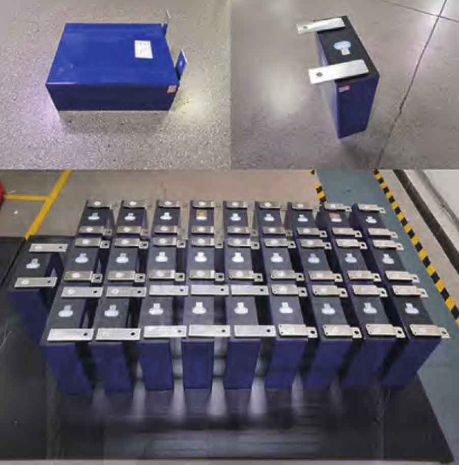
The experiment used a square aluminum shell 280 Ah lithium iron phosphate battery cell, with a positive electrode material of lithium iron phosphate (LiFePO4) and a negative electrode material of graphite. The cell sample is shown in Figure 1. In this experiment, the average heating capacity of the battery cell under the rated charging and discharging rate of 0.5 P is 13 W, and the battery cell is the main heat source in the energy storage battery compartment.
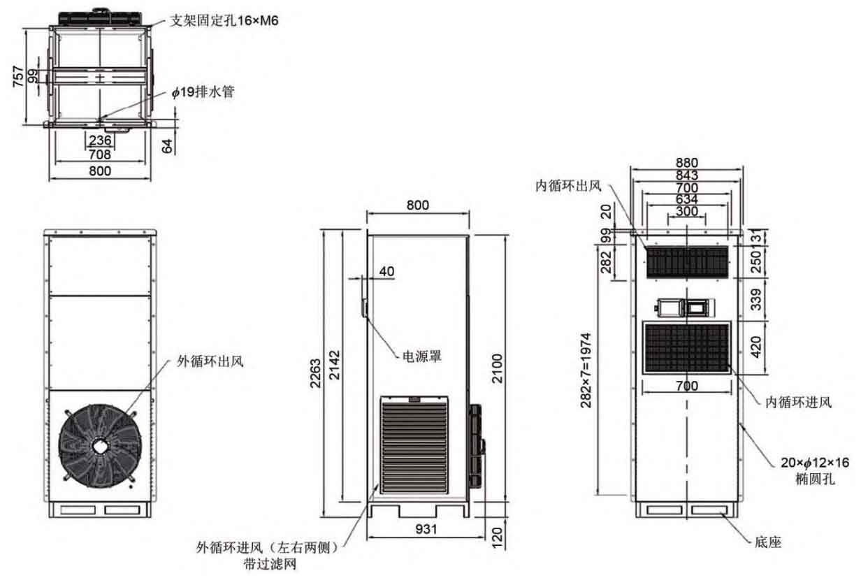
The experiment used an external mounted air conditioner (produced in Wuxi) with a customized cooling capacity of 25 kW. The air conditioning adopts an upper air outlet and lower air return design, and the size parameters are shown in Figure 2. The air duct is installed on the cabin roof and side walls, and the air conditioning outlet is connected to the air duct to send cold air to the battery cluster. The battery module’s own fan draws cold air to cool the battery cells. The air duct is guided to ensure reasonable airflow organization in the cabin, and the temperature rise of the battery module is uniform and consistent.
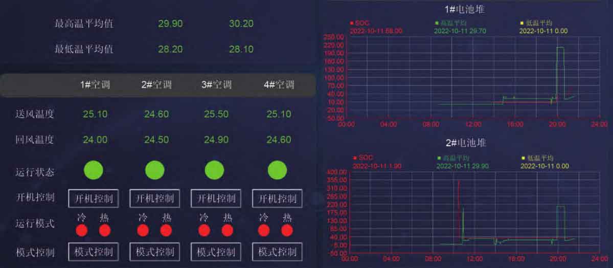
The experiment used a three-phase multifunctional electricity meter (produced in Jiangsu) to measure the power consumption of air conditioning operation. The battery management system (BMS) is used for cell temperature collection in this experiment, with an accuracy of ± 1 ℃ for individual cell temperature collection. BMS collects the high and low temperature values of the reactor core, and sends the collected values to PCS-9726 through communication. Each battery stack is equipped with 1 BMS. The air conditioning control device PCS-9726 is used to obtain temperature values collected by BMS and compare them with fixed values, and output corresponding instructions to the cabin air conditioning execution unit. The experiment uses EMS backend software, as shown in Figure 3, which can monitor and control the energy storage system equipment, manage energy, and achieve local setting of plan curves for charge and discharge management.
1.2 Experimental Platform
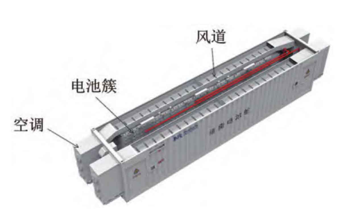
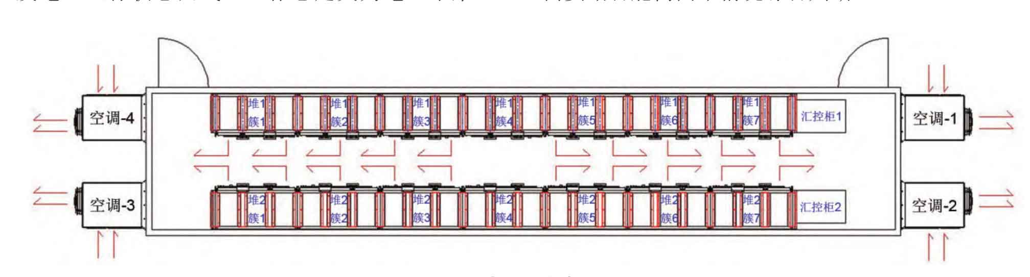
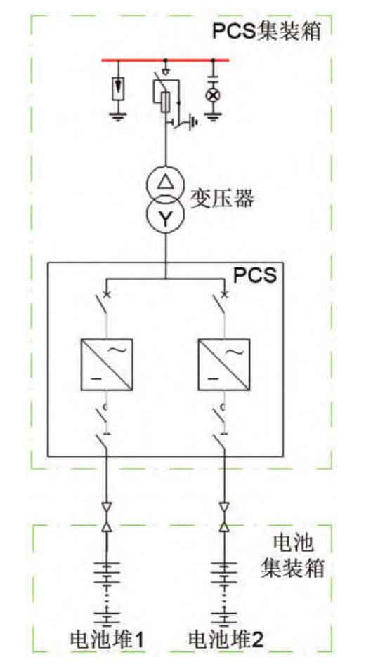
The experiment was conducted in a 5.017 MWh energy storage battery compartment (13716 mm × 2700 mm × Within 3100 mm, as shown in Figure 4. The battery compartment contains 2 battery stacks, each consisting of 7 parallel battery clusters. Each battery cluster is composed of 25 modules connected in series, which contain 1 and 16 series of lithium iron phosphate cells. The arrangement inside the battery compartment is shown in Figure 5, with two battery stacks arranged on both sides of the long side. Air conditioning is installed at the four corners of the compartment, with a return air duct in the middle and a supply air duct at the top, evenly supplying air to each column within the cluster.
1.2.1 Control strategy
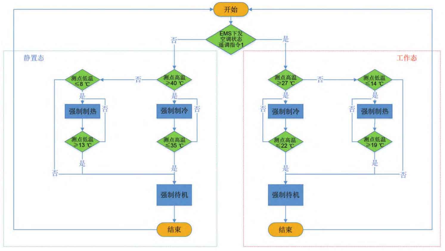
According to Figure 6, EMS defines the operating state curve of the power generation cell based on the daily charging and discharging plan curve: the working state is defined as the battery having charging and discharging instructions or being in charging and discharging state within the next 2 hours; The static state is defined as the battery being in a non charging and discharging state without charging and discharging instructions within the next 2 hours. If EMS is determined to be in working state, logical judgment shall be made according to the corresponding temperature setting on the right side of Figure 6; If EMS determines that it is in a stationary state, logical judgment should be made according to the temperature setting on the left side of Figure 6. Obviously, the temperature range of the stationary state is relatively larger, and the temperature requirements for the battery cell are more relaxed. When standing still, the temperature of the battery cell can be adjusted to the hot standby state within 2 hours to avoid irreversible capacity loss caused by low-temperature or high-temperature charging and discharging of the battery cell. The stack level BMS is the minimum input unit for air conditioning control. The BMS sends the collected cell temperature to the air conditioning control device PCS-9726, and outputs the stack level command in combination with the state constant value. The heap level command is not the final command actually output to the air conditioner, and needs to be comprehensively judged based on the situation of the two piles in the cabin.
1.2.2 Static state control strategy
When the air conditioning control device PCS-9726 obtains that the battery cell is in a static state, the target temperature of the battery cell for forced cooling is 38 ℃, and there is a 3 ℃ return difference and a 2 ℃ dead zone. That is, when the temperature of the battery cell is greater than or equal to 40 ℃, the air conditioning cooling is forcibly turned on; When the temperature of the battery cell is less than or equal to 35 ℃, the air conditioning cooling stops. When in a static state, the target temperature of the battery cell for forced heating by the air conditioner is 10 ℃, with a 3 ℃ return difference and a 2 ℃ dead zone. That is, when the temperature of the battery cell is less than or equal to 8 ℃, the air conditioner is forced to start heating; When the temperature of the battery cell is greater than or equal to 13 ℃, the air conditioning heating stops. The temperature range of the battery cell when the air conditioning system enters forced standby mode is between 8 and 40 ℃. When the air conditioning system is in forced standby mode, the air conditioning circulating fan also stops running.
1.2.3 Working state control strategy
When the air conditioning control device PCS-9726 obtains that the battery cell is in working mode, the target temperature of the battery cell for forced cooling is 25 ℃, and there is a 3 ℃ return difference and a 2 ℃ dead zone. That is, when the temperature of the battery cell is greater than or equal to 27 ℃, the air conditioning cooling is forcibly turned on; When the temperature of the battery cell is less than or equal to 22 ℃, the air conditioning cooling stops. When in working mode, the target temperature of the battery cell for forced heating by the air conditioner is 16 ℃, with a 3 ℃ return difference and a 2 ℃ dead zone. That is, when the temperature of the battery cell is less than or equal to 14 ℃, the air conditioner is forced to start heating; When the temperature of the battery cell is greater than or equal to 19 ℃, the air conditioning heating stops. The temperature range of the battery cell when the air conditioning system enters forced standby mode is 14-27 ℃. When the air conditioning system is in forced standby mode, the air conditioning circulating fan also stops running.
The four air conditioners are centrally controlled on a cabin basis. After uniformly processing the temperature data of the battery cells sent by the two BMS in the cabin, PCS-9726 outputs the same command to all air conditioners to avoid command conflicts. Logic judgment for battery stack 1 and battery stack 2: If forced cooling and forced standby exist simultaneously, execute forced cooling; If forced heating and forced standby coexist, execute forced heating; If forced cooling and forced heating coexist, execute automatic operation of the air conditioning. If any BMS communication is interrupted, the entire cabin will execute automatic air conditioning operation.
1.3 Experimental Plan
The energy storage monitoring system is connected to 2 BMS and 4 air conditioners in the battery compartment through Modbus communication. The air conditioning sampling cycle is set to 1 time/min, the battery cell sampling cycle is 30 times/min, and the command output cycle is 1 time/min to ensure normal data storage. Before the formal experiment, PCS-9726 was manually set to test the control of air conditioning: forced cooling, forced heating, forced standby, and automatic operation modes can be freely switched.
As shown in Figure 7 and Table 1, first adjust the SOC of battery stack 1 to 100%, and then adjust the SOC of battery stack 2 to 0%. After standing at ambient temperature for 5 hours, battery stack 1 is discharged into the system through a PCS energy storage converter, and battery stack 2 is charged. In this charging and discharging experiment, the air conditioner was automatically controlled by the return air temperature, without adding a control strategy. During this time, the air conditioning power consumption and cell temperature data were recorded. Readjust the SOC of battery stack 1 to 100%, and battery stack 2 to 0%. Allow to stand at ambient temperature for 5 hours, discharge battery stack 1, and charge battery stack 2. In this charging and discharging experiment, an air conditioning control strategy was added to compare the data results of the two experiments.
| Experiment | Control Strategy | Battery stack 1 | Battery stack 2 |
| First experiment | √ | Discharge SOC 100%~0%~standby | Charging SOC 0%~100%~standby |
| Second experiment | X | Discharge SOC 100%~0%~standby | Charging SOC 0%~100%~standby |
2. Results and Discussion
2.1 Impact of control strategy on temperature difference of battery cells
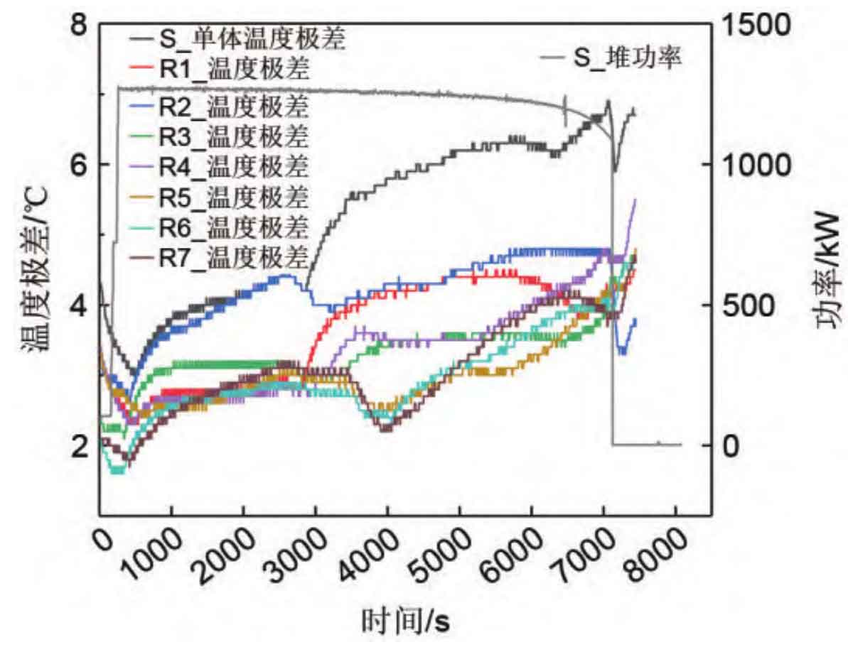
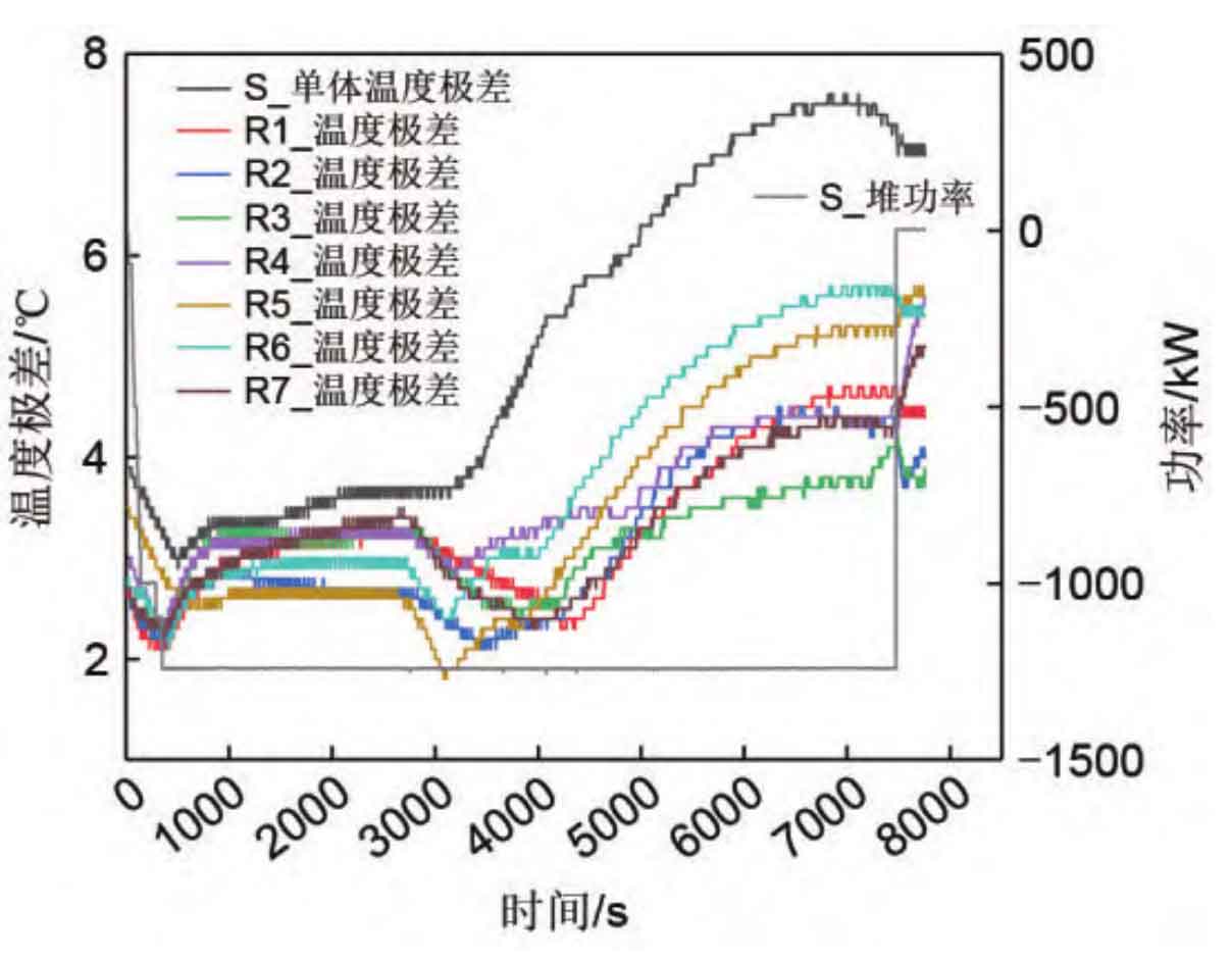
From Figure 8, it can be seen that in the early stage of discharge in reactor 1 (0-500 s), the power rapidly increases, and at this time, both the temperature range of the core inside the reactor and the temperature range inside the cluster show a downward trend. In the figure, S represents the heap and R represents the cluster, which is consistent with the following text. The reason is that after the last charge and discharge, the temperature of the battery cells in the cabin did not reach consistency, resulting in a certain temperature difference. At the beginning of the discharge, the power was low, and the heat generated by the battery cells was low, almost ignoring the temperature difference caused by inconsistent heating between the battery cells. As shown in Figure 9, at this time, the module fan was working, the air conditioning was not started, and the air temperature involved in heat exchange was higher, with a smaller temperature difference from the lowest temperature battery cell, while the highest temperature battery cell was cooled, Causing a decrease in the temperature difference between the battery cells. As the discharge power increases to 0.5 P, there are differences in heating conditions among different battery cells, as well as uneven heat dissipation, resulting in an increase in the temperature difference between individual high and low temperature battery cells.
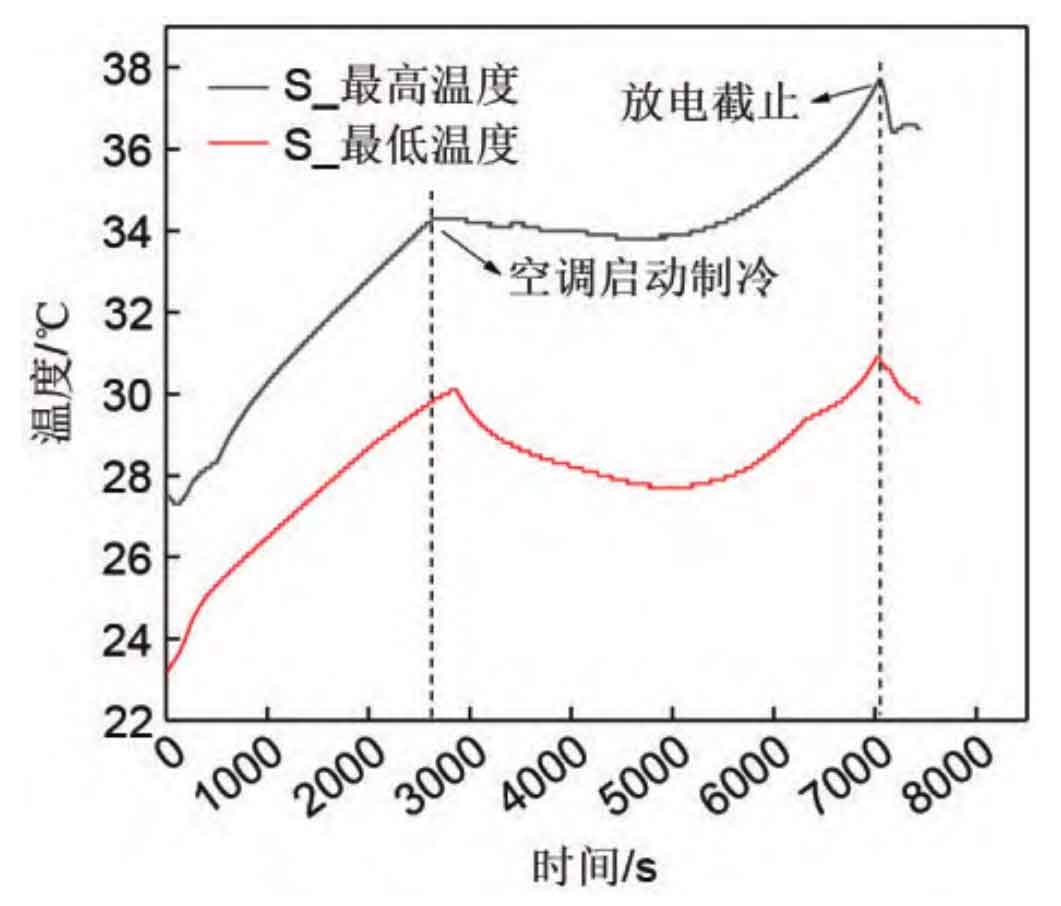
At around 2600 seconds, there was a significant turning point in the temperature range of the reactor cell and the temperature ranges of cluster 1, cluster 2, and cluster 3. At this point, the air conditioning began to cool, and low-temperature air was sucked into the module by the fan. The highest temperature cell was quickly cooled, while the lowest temperature cell remained elevated, resulting in a sudden decrease in temperature difference.
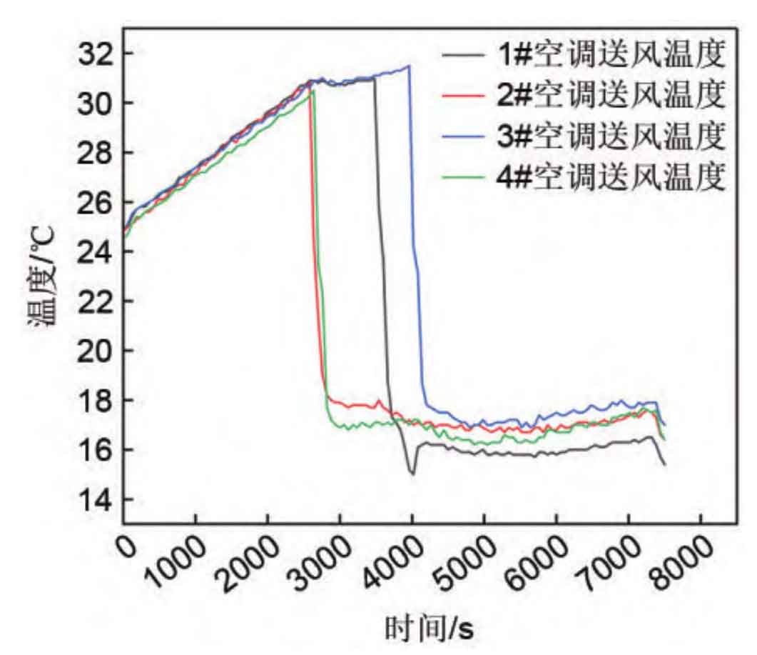
Around 3500 seconds, there is a turning point in the temperature range of the battery cells in clusters 5, 6, and 7. The difference in the occurrence time of inflection points between clusters is mainly due to the inconsistent start time of air conditioning. As shown in Figure 10, the second and fourth air conditioners are prioritized to start around 2500 seconds, with the first air conditioner lagging behind the second air conditioner by about 700 seconds, and the third air conditioner lagging behind by about 1300 seconds. The main reason for inconsistent start of air conditioning is that when no control strategy is added, the air conditioning starts cooling through independent judgment of the return air temperature. Due to differences in the collection of return air temperature sensors at different positions, a certain air conditioner prioritizes starting cooling, and a decrease in air temperature will further delay the start of other air conditioners. Due to the proximity of cluster 1, cluster 2, and cluster 3 to air conditioner 4, the inflection point of the battery cell temperature difference appears earlier than cluster 5, cluster 6, and cluster 7. The randomness of air conditioning startup further leads to inconsistency in battery cell temperature, which has a great impact on engineering applications. As the discharge progresses, the temperature difference between the battery cells continues to increase until the discharge ends. Cold air not only controls the temperature rise of the battery cell, but also increases temperature non-uniformity. Li Cunjun also found in the heat dissipation experiment of lithium-ion power batteries that a decrease in coolant temperature would increase the temperature difference of the battery cells.
At around 7000 seconds, the PCS entered standby mode and the temperature difference between the battery cells showed a turning point again. According to the energy conservation equation, the heat generated by lithium batteries is balanced through self absorption and heat exchange with the environment:
In the formula, Q is the heat generated by the battery cell; Qz is the heat absorbed by the cell itself; Qh is the heat exchanged between the battery cell and the environment. The heat absorbed by the battery cell itself is manifested as a change in temperature:
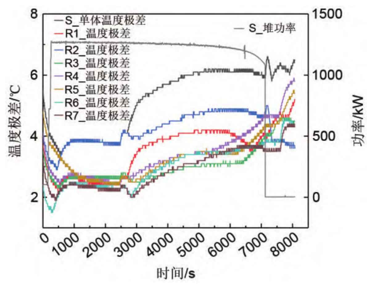
In the formula, mk and Cpk respectively represent the mass and specific heat capacity of each component material of the battery; ∆ T is the change in battery temperature. The main ways of heat transfer in batteries are thermal radiation, thermal conduction, and thermal convection. The larger the temperature difference between the ambient temperature and the surface of the battery cell, the stronger the convective and radiative heat transfer, i.e. the greater the Qh. When the discharge is cut off, the heat production Q of the cells is almost zero, and the temperature difference between the cells caused by inconsistent heating can be ignored. High temperature cells, due to the larger heat exchange temperature difference, cool down faster, and the temperature difference between the cells decreases.
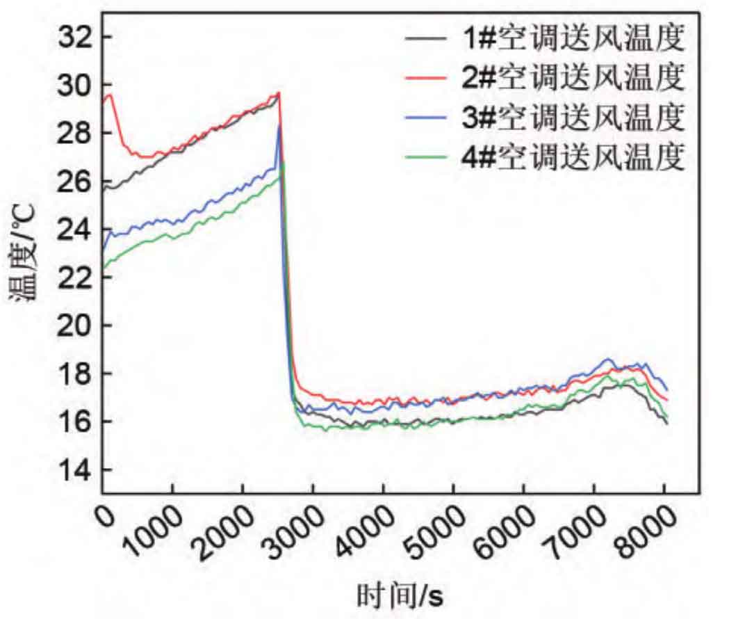
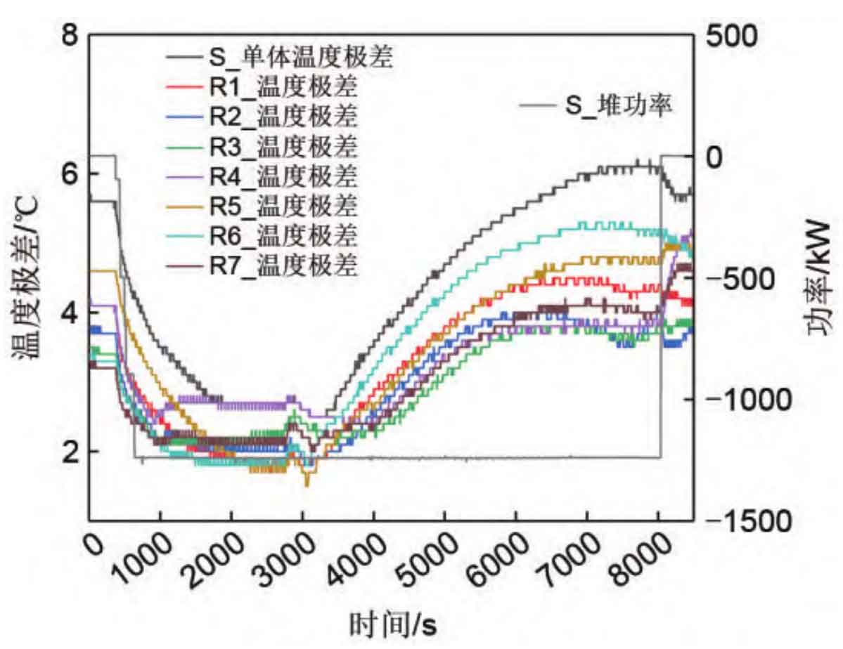
But as the fan of the module stops rotating, the difference in air intake between the upper and lower modules within the cluster becomes larger. The module near the air duct outlet has better heat dissipation effect, while the heat dissipation far away from the outlet becomes worse, and the temperature difference further increases. During the discharge process (excluding standby), the maximum temperature difference inside the reactor reaches 6.8 ℃. During the second discharge experiment of battery stack 1, an air conditioning control strategy was added. As shown in Figure 11, the overall trend of temperature difference changes in the battery cells remained consistent with the first experiment. From Figure 12, it can be seen that the air supply temperature of the air conditioning system decreases simultaneously, indicating that the four air conditioners have simultaneously executed the forced cooling command issued by the controller. Therefore, due to the influence of cold air intake, the temperature difference of each cluster cell decreases simultaneously at around 2500 seconds and gradually increases. Until the discharge is cut off, the maximum temperature difference between the core cells in the reactor reaches 5.9 ℃. Compared to the first discharge experiment, the temperature difference decreased by 0.9 ℃.
In the first experiment, the temperature difference curve of battery cell 2 without the addition of control strategy was more discrete, as shown in Figure 13. After the air conditioning refrigeration started, due to the difference in starting sequence, clusters 5, 6, and 7 closer to air conditioning 2 first showed temperature inflection points, causing the temperature difference inside the stack to be amplified. And after the air conditioning is turned on for a period of time, it is unfavorable for the temperature difference of the battery cells, and the rate of temperature difference increase is accelerated. During the charging process, the maximum temperature difference inside the reactor occurs at the end of the charging period, reaching 7.6 ℃. As shown in Figure 14, after adding the control strategy, the temperature difference curve of battery stack 2 tends to be consistent, and the temperature range inside the stack is close to the maximum cluster temperature range (cluster 6), indicating better consistency of the cell temperature. The temperature difference limit inside the stack is 6.2 ℃, which is 1.4 ℃ lower than the first discharge experiment.
2.2 Impact of control strategies on air conditioning energy consumption
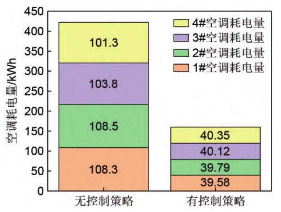
Due to the relatively suitable environmental temperature under testing conditions, there is no need to heat or cool the battery cell when it is stationary, and the battery cell temperature is always within the operating temperature range. Therefore, after adding a control strategy, the air conditioner remained in a forced standby state for most of the time outside the charging and discharging period. At this time, the internal circulation fan stopped running, significantly reducing power consumption. The measured power of the internal circulation fan in the air conditioner was 3.5 kW, as shown in Figure 16. The total daily power consumption of the air conditioner decreased by 62% compared to when there was no control strategy.
3.Conclusion
This work takes the 5.017 MWh energy storage battery compartment as the experimental object, proposes a thermal management control strategy based on EMS planning curve and cell temperature, and analyzes the impact of applying this strategy on cell temperature difference and air conditioning power consumption. By conducting 0.5 P constant power charging and discharging on two energy storage battery stacks, the energy-saving and temperature difference control effects of this strategy were verified. The main conclusions drawn from this work and several optimization measures for the thermal management system are as follows.
(1) When there is no control strategy, the air conditioner collects temperature through the internal circulation fan to achieve mode switching. This control method has randomness, and the cabin air conditioning cannot start and stop at the same time, resulting in asymmetric air output and accumulation of temperature difference in the battery cells. After adding a control strategy, precise control of the air conditioning is achieved by collecting the temperature of the battery cells. The air conditioning starts and stops simultaneously, reducing the accumulation of temperature differences and making the battery cell temperature more uniform. Based on test data, the temperature difference between the cores of Reactor 1 decreased by 0.9 ℃, while the temperature difference between the cores of Reactor 2 decreased by 1.4 ℃.
(2) After the air conditioning is activated, it has a control effect on the temperature rise of the battery cell, but the impact on the temperature difference is negative. The reason is that under existing integration conditions, the air flow of different battery clusters, modules, and cells cannot be completely consistent, and the intervention of cold air will increase the inconsistency of cell temperature.
(3) The module fan also has a significant impact on the temperature difference of the battery cell. When the battery cell is in standby mode, stopping the module fan will cause a sudden increase in temperature difference. Therefore, it is necessary to consider delaying the fan shutdown time or adding longitudinal variable cross-section air ducts to balance the cold air flow of different modules.
(4) After adding the control strategy, under the mandatory standby command, the circulating fan in the air conditioner stops running, which can greatly reduce daily power consumption. With one charge and one discharge per day, the daily power consumption is reduced by 62%. In winter or summer, when the cell temperature is in the non operating temperature range, this strategy will further increase the energy-saving effect.
Therefore, in terms of control strategy, centralized control should be considered for multiple sets of thermal management equipment in the cabin, to avoid differentiated start and stop between each equipment and improve the consistency of thermal management. At the same time, it is necessary to collect the temperature of the battery cell as the judgment basis for the thermal management system to improve the sensitivity of thermal management. In terms of structural design, horizontal and vertical variable cross-section air ducts are used, with variable porosity module air intakes to ensure the uniformity of air supply between clusters and modules. In terms of energy-saving optimization, thermal management control should be combined with the operating conditions of the battery cell to improve the operational efficiency of the energy storage system.