
The evolution of urban public transportation continuously seeks solutions that balance efficiency, cost, and environmental impact. As a researcher deeply engaged in the field of traction power systems, I have focused on addressing the inherent challenges of conventional tram power supply. The traditional paradigm, reliant on extensive catenary systems or third rails directly fed from the city grid, presents issues such as visual pollution, high infrastructure costs, significant energy losses, and the injection of harmonics back into the utility network. My investigation centers on a transformative alternative: a cell energy storage system (CESS) that decouples the tram’s immediate power demand from the grid, offering a pathway to more sustainable and economical urban rail transit.
The core principle of this approach is to utilize a high-capacity battery bank as an intermediate energy buffer. This cell energy storage system is charged during off-peak hours, typically at night when grid electricity is cheaper and demand is low. The stored energy is then used to power trams throughout the day. Crucially, this architecture enables the efficient recovery of regenerative braking energy—a substantial amount of kinetic energy otherwise wasted as heat in braking resistors. By capturing and reusing this energy within the cell energy storage system, overall system efficiency is markedly improved. The primary objectives of this research are to design a robust system architecture, develop effective control strategies for power management, and validate the performance through experimental prototyping, thereby demonstrating the feasibility and advantages of a battery-based, catenary-free tram power solution.
System Architecture and Operational Principles
The proposed novel power supply system is architected around a ground-based cell energy storage system. Its primary components and energy flow are designed to ensure reliable, stable, and intelligent power delivery to the tram. The schematic architecture can be broken down into distinct functional blocks:
- Grid Interface and Charging Unit: This subsystem connects to the three-phase AC utility grid (e.g., 380V, 50Hz). It includes a rectifier transformer that steps up the voltage to a suitable level for efficient conversion, followed by an AC/DC converter. This converter acts as a controlled battery charger, responsible for replenishing the ground-based cell energy storage system with energy from the grid.
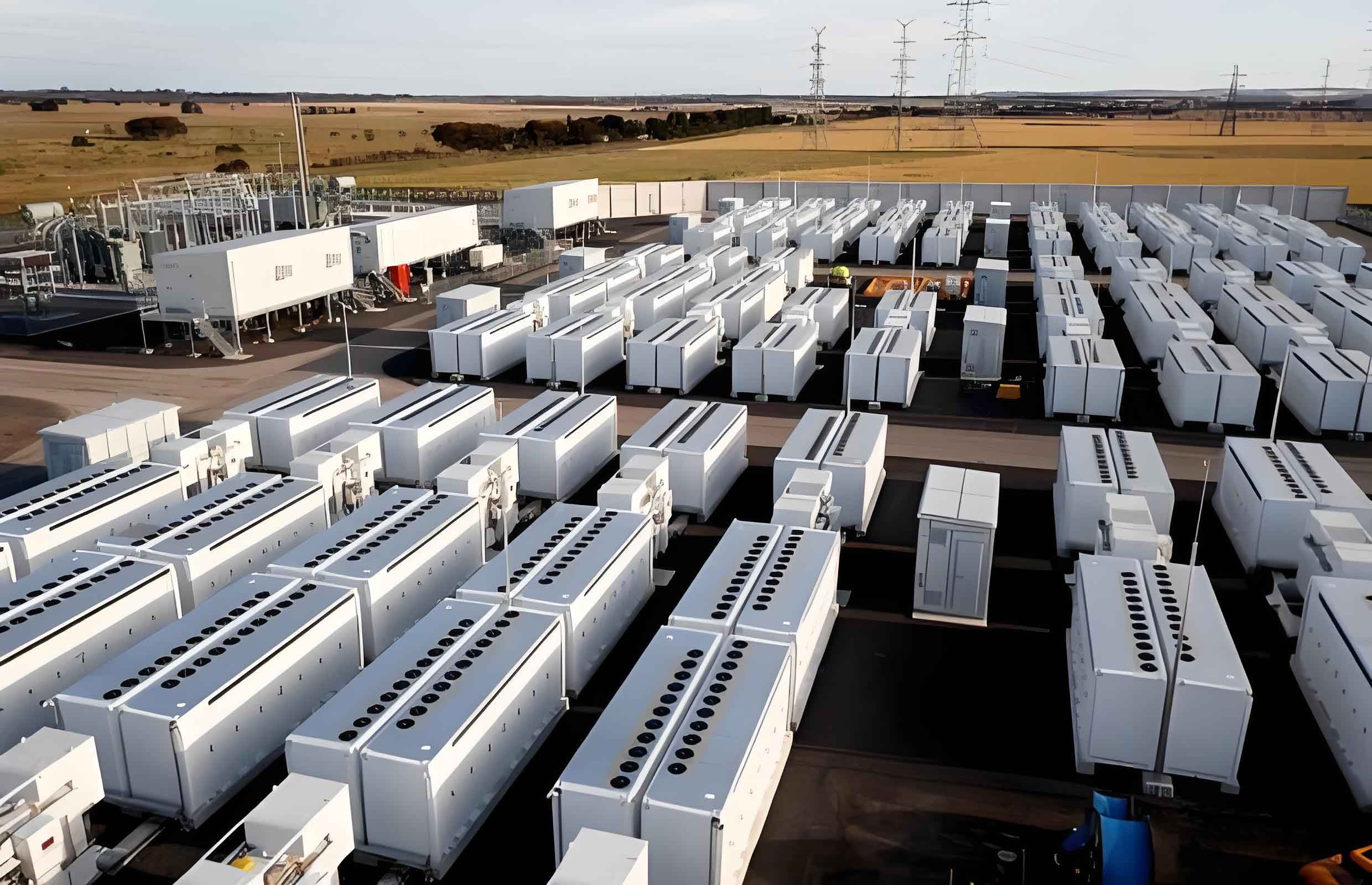
- Core Energy Reservoir – The Battery Bank: This is the heart of the cell energy storage system. For this study, lead-acid batteries were selected due to their mature technology, high reliability, favorable cost-performance ratio for high-power applications, and ability to handle frequent charge-discharge cycles typical in transit applications. The battery bank operates at a nominal DC voltage (e.g., 1200V).
- Bi-Directional Power Interface: A bidirectional DC/DC converter serves as the critical link between the battery bank and the tram’s traction network. It performs two essential functions: in the primary direction (Boost mode), it steps up the variable battery voltage to a constant, high-voltage DC bus (e.g., 1500V) required by the tram’s traction inverters. In the reverse direction (Buck mode), it channels the regenerative braking energy from the DC bus back into the battery bank for storage.
- Traction Power Distribution and Protection: This includes the positive feeder cabinet, which houses protection devices like circuit breakers and contactors, and the current collection rails. It ensures safe and controlled power delivery to the tram.
- Braking Energy Management Backup: A chopper circuit with a braking resistor is installed across the DC bus. This is a safety-critical component. It activates only if the DC bus voltage exceeds a safe maximum threshold (e.g., 1650V), which might occur if the battery is fully charged and cannot accept more regenerative energy. The chopper dissipates the excess power as heat, protecting the system from overvoltage.
The operational sequence is as follows: During scheduled charging periods, the AC/DC charging unit draws power from the grid and charges the battery bank using controlled constant-current (CC) and constant-voltage (CV) algorithms. During tram operation, the bidirectional DC/DC converter draws energy from the cell energy storage system, regulates it to the precise traction voltage, and supplies it to the tram via the distribution network. When the tram brakes, its traction system acts as a generator, raising the voltage on the DC bus. The bidirectional converter senses this, switches to Buck mode, and feeds this energy back into the battery bank. This closed-loop energy management is fundamental to the system’s high efficiency.
Mathematical Modeling and Control Strategy Formulation
The efficacy of the proposed cell energy storage system hinges on sophisticated control strategies for both the AC/DC charger and the bidirectional DC/DC converter. These strategies are derived from mathematical models of the power stages.
AC/DC Charging Unit Control
The charger must safely and efficiently charge the large-scale battery bank. The control employs a cascaded loop structure. The outer loop regulates either voltage or current, while the inner loop controls the input current to achieve power factor correction and low harmonic distortion.
Constant Current (CC) Charging Mode: Used for bulk charging. The control law is based on the error between the reference charging current \(I_{bat}^*\) and the measured battery current \(I_{bat}\).
$$
I_{err}(t) = I_{bat}^* – I_{bat}(t)
$$
$$
D_{cc}(t) = K_{p\_cc} \cdot I_{err}(t) + K_{i\_cc} \cdot \int I_{err}(t) \, dt
$$
Here, \(D_{cc}(t)\) is the duty cycle command for the charger’s power switches, and \(K_{p\_cc}\), \(K_{i\_cc}\) are the proportional and integral gains of the PI controller. This ensures the battery receives a stable, predetermined current.
Constant Voltage (CV) Charging Mode: Used during the final charging stage to prevent overcharging. It regulates the battery terminal voltage \(V_{bat}\) to a setpoint \(V_{bat}^*\).
$$
V_{err}(t) = V_{bat}^* – V_{bat}(t)
$$
$$
D_{cv}(t) = K_{p\_cv} \cdot V_{err}(t) + K_{i\_cv} \cdot \int V_{err}(t) \, dt
$$
The controller automatically transitions from CC to CV mode when the battery voltage approaches its maximum allowable value.
Bidirectional DC/DC Converter Control
This converter is the workhorse of the real-time cell energy storage system operation. Its control must be seamless and robust for both power flow directions. The control modes are summarized in the table below:
| Operation Mode | Power Flow | Primary Control Objective | Secondary Limit |
|---|---|---|---|
| Boost (Tram Motoring) | Battery → DC Bus | Regulate DC Bus Voltage (\(V_{bus}^*\)) | Limit Battery Discharge Current (\(I_{dis}^*\)) |
| Buck (Regenerative Braking) | DC Bus → Battery | Regulate Battery Charging Current (\(I_{chg}^*\)) OR Battery Voltage (\(V_{bat}^*\)) | Limit DC Bus Voltage Rise |
Boost Mode Control (Tram Powering): The primary goal is to maintain a rock-solid DC traction voltage \(V_{bus}\). The controller adjusts the converter’s duty cycle \(\alpha_{boost}\) based on the voltage error.
$$
V_{bus\_err}(t) = V_{bus}^* – V_{bus}(t)
$$
$$
\alpha_{boost}(t) = K_{p\_boost} \cdot V_{bus\_err}(t) + K_{i\_boost} \cdot \int V_{bus\_err}(t) \, dt
$$
The relationship between input (battery) and output (bus) voltage in ideal Boost operation is: $$ V_{bus} = \frac{V_{bat}}{1 – \alpha_{boost}} $$. The controller dynamically adjusts \(\alpha_{boost}\) to compensate for load changes and battery voltage droop, ensuring \(V_{bus}\) remains constant.
Buck Mode Control (Regeneration): When regenerative braking is detected (\(V_{bus} > V_{bus}^*\)), the controller switches to Buck mode. The control objective can be either to limit the charging current to the battery (CC mode, for safe fast absorption) or to prevent battery overvoltage (CV mode). The duty cycle \(\alpha_{buck}\) is controlled similarly. The ideal Buck conversion is: $$ V_{bat} = \alpha_{buck} \cdot V_{bus} $$. A seamless transition logic between these modes is critical for stable operation of the overall cell energy storage system.
Hardware Platform Design and Implementation
To validate the theoretical models and control strategies, a scaled-down 50 kW experimental prototype of the cell energy storage system was designed and constructed. The hardware design emphasizes modularity, computational power, and reliability.
The core of the control system is built around dual high-performance digital signal processors (DSPs), specifically the TMS320C28346. This architecture segregates tasks for optimal performance:
- DSP1 (Master Controller & Communication Handler): Manages high-level system supervision, state machine logic, and all communication protocols (Ethernet for SCADA, CAN bus for Battery Management System (BMS) interface, RS-485 for local HMI).
- DSP2 (Real-Time Power Control Core): Dedicated to time-critical tasks. It executes all the PI control algorithms for the AC/DC and DC/DC converters at high switching frequencies, generates the PWM signals for the power semiconductor devices (IGBTs), handles digital I/O for contactors and breakers, and implements fast hardware-based protection routines (overcurrent, overvoltage).
The main power circuit parameters for the prototype are listed below:
| Component | Parameter | Value |
|---|---|---|
| AC/DC Charging Unit | AC Input | 380 V, 50 Hz, 3-Phase |
| DC Output Range | 300 – 600 V | |
| Rated Power | 50 kW | |
| Bidirectional DC/DC | Input Voltage Range | 300 – 600 V (from Battery) |
| Output Voltage (Regulated) | 800 V | |
| Rated Output Current | 60 A | |
| Rated Power | 48 kW | |
| Cell Energy Storage System | Battery Type & Nominal Voltage | Lead-Acid, 1200 V |
Experimental Validation and Performance Analysis
The constructed 50 kW prototype platform was subjected to comprehensive testing to evaluate the performance of the proposed cell energy storage system. The load was simulated using a resistive load bank of 14 Ω.
Test 1: Grid-to-Battery Charging. The AC/DC charging unit was activated to charge the lead-acid battery bank. The waveforms captured demonstrated excellent performance. The output DC voltage was smoothly regulated to the desired charging profile. The charging current was stable and precisely controlled according to the CC/CV algorithm. Furthermore, the grid-side current waveforms showed a high power factor and low total harmonic distortion (THD), confirming that the charger minimizes pollution to the utility grid—a key advantage over traditional uncontrolled rectifiers.
Test 2: Battery-to-Load Power Supply (Simulating Tram Motoring). The bidirectional DC/DC converter operated in Boost mode to power the resistive load. The results were conclusive: the output DC bus voltage rapidly rose and settled at the commanded 800 V within 500 milliseconds. It maintained remarkable stability despite variations in the battery source voltage and load conditions. The output current corresponded cleanly to the load demand. This test validated that the cell energy storage system can provide a stable, high-quality traction power source, emulating the continuous power delivery required by a moving tram.
Test 3: Regenerative Braking Simulation. A test was conducted to simulate regenerative braking by injecting a DC voltage source onto the bus. The system correctly detected the rising bus voltage, instantaneously commanded the bidirectional converter into Buck mode, and successfully channeled the simulated braking energy back into the battery bank, lowering the bus voltage to its setpoint. The smooth transition between operational modes was verified, demonstrating the system’s capability for energy recovery.
Conclusion and Future Outlook
This research comprehensively detailed the design, control, and implementation of a novel cell energy storage system for modern tramways. The proposed system fundamentally rethinks the traction power paradigm by using a ground-based battery bank as a buffer and energy manager. The architecture successfully integrates grid charging during off-peak hours, high-efficiency bidirectional power conversion for traction supply, and sophisticated control for regenerative braking energy recovery.
Theoretical analysis, supported by experimental results from a 50 kW functional prototype, confirms the system’s viability. Key demonstrated benefits include: the ability to provide a stable and continuous traction voltage independent of grid fluctuations; significant improvement in overall energy efficiency through regeneration capture; reduction in grid harmonic pollution; and the potential for catenary-free operation in city centers, reducing visual impact and infrastructure costs. The implemented control strategies—using cascaded PI loops for constant current and constant voltage regulation in both charging and discharging modes—proved effective for managing the complex energy flows within the cell energy storage system.
Future work will focus on scaling the prototype to full operational power levels (megawatt scale), integrating advanced battery chemistries like Lithium-Ion for higher energy density and cycle life within the cell energy storage system, and developing more advanced, predictive energy management systems that optimize charging and discharging based on tram schedule and real-time grid conditions. The findings of this research strongly indicate that battery-based energy storage systems hold immense potential for revolutionizing the sustainability and economic feasibility of urban rail transit networks.