
In recent years, the growing global energy crisis and environmental concerns have accelerated the adoption of renewable energy sources, with solar power standing out due to its abundance, cleanliness, and accessibility. Off-grid solar systems, in particular, play a critical role in providing electricity to remote areas such as mountainous regions and pastoral communities, where grid connectivity is impractical. However, these systems often face challenges related to energy efficiency, battery lifespan, and operational reliability, primarily due to inadequate energy management strategies. This article explores a coordinated control approach for off-grid solar systems, focusing on maximizing energy utilization while ensuring battery safety and meeting load demands. Through detailed modeling and simulation, we demonstrate how integrating maximum power point tracking (MPPT) and load power tracking control can enhance system performance. The models developed include photovoltaic (PV) panels, batteries, DC/DC converters, and inverters, all simulated under varying environmental conditions to validate the proposed strategy.
The fundamental components of an off-grid solar system are illustrated in the following figure, which shows the energy flow and interconnections. This structure forms the basis for our analysis and control design.
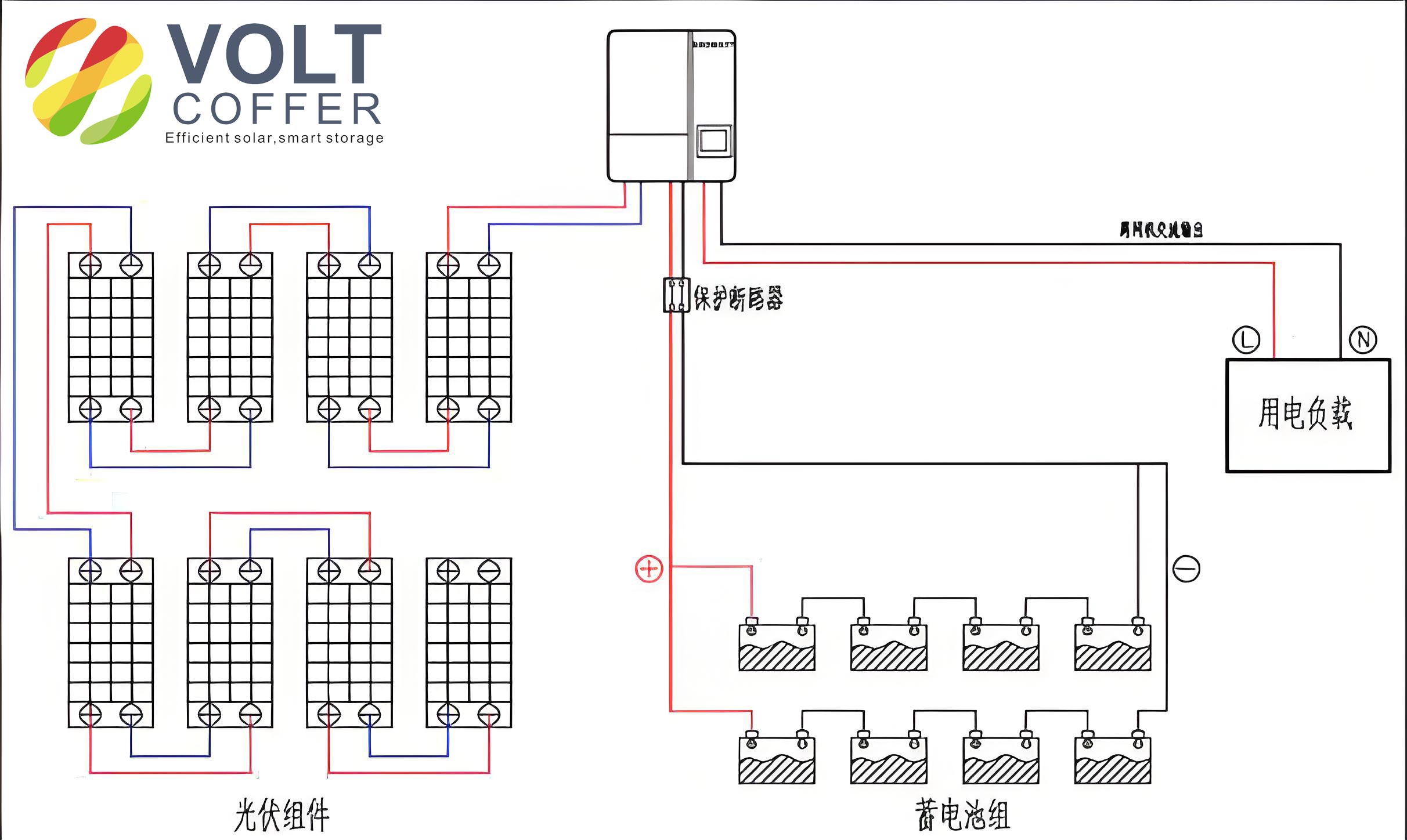
An off-grid solar system typically consists of PV panels that convert solar energy into electrical energy, a battery bank for energy storage, a DC/DC Buck converter to regulate voltage, a controller for managing power flow, and an inverter to convert DC power to AC for household appliances. The PV panels serve as the primary energy source, with their output fluctuating based on solar irradiance and temperature. The battery storage is crucial for balancing supply and demand, providing power when PV generation is insufficient, such as during nighttime or cloudy periods. The Buck converter steps down the PV output voltage to a level suitable for battery charging and load supply, while the inverter enables the use of standard AC loads. The controller orchestrates the entire system, implementing strategies like MPPT to maximize energy harvest and power tracking to prevent battery overcharging or excessive discharge. This integrated setup ensures that the off-grid solar system operates autonomously and reliably, even in dynamic weather conditions.
The energy flow in an off-grid solar system must adhere to the principle of energy conservation, where the total energy generated by the PV panels equals the sum of energy consumed by the load and stored in the battery. However, solar irradiance and load demand vary throughout the day, creating a dynamic relationship that requires careful coordination. For instance, peak solar generation may not coincide with peak load demand, necessitating the battery to act as a buffer. To manage this, we propose a control strategy that switches between different operational modes based on real-time conditions. Let \( P_s \) denote the PV power output, \( Q \) the solar irradiance, \( P_c \) the battery charging power, \( P_l \) the load power, and \( P_{c_{\text{max}}} \) the maximum acceptable charging power for the battery. The system modes include:
- Mode 1: When \( P_s – P_c – P_l > P_{c_{\text{max}}} \), the system performs power tracking control to limit battery charging to a safe constant voltage and current.
- Mode 2: When \( 0 \leq P_s – P_c – P_l < P_{c_{\text{max}}} \), the system engages in MPPT to charge the battery at the maximum possible rate.
- Mode 3: When \( P_s – P_c – P_l < 0 \), the system operates in MPPT mode, and the battery discharges to supplement the load.
- Mode 4: When \( Q = 0 \) and \( P_l \neq 0 \) (e.g., at night or on cloudy days), the PV panels are inactive, and the battery solely powers the load.
This coordinated control ensures that the off-grid solar system prioritizes load satisfaction while protecting the battery from overcharge or deep discharge, thereby extending its lifespan. The control logic continuously monitors parameters like battery state of charge (SOC) and voltage thresholds to transition between modes seamlessly. For example, if the battery voltage exceeds a safe upper limit during high irradiance, the controller switches from MPPT to power tracking, reducing PV output to match the load and safe charging power. This approach enhances the overall efficiency and reliability of the off-grid solar system.
Maximum power point tracking is essential for optimizing energy harvest from PV panels in an off-grid solar system. Among various MPPT methods, the incremental conductance (IncCond) algorithm is preferred for its accuracy and stability. It relies on the principle that at the maximum power point (MPP), the derivative of power with respect to voltage is zero, i.e., \( \frac{dP}{dV} = 0 \). Mathematically, this can be expressed as:
$$ \frac{dP}{dV} = \frac{d(IV)}{dV} = I + V \frac{dI}{dV} = 0 $$
which implies:
$$ \frac{dI}{dV} = -\frac{I}{V} $$
The IncCond algorithm compares the instantaneous conductance (\( I/V \)) to the incremental conductance (\( \Delta I / \Delta V \)) to determine the direction of voltage adjustment. If \( \frac{dI}{dV} > -\frac{I}{V} \), the operating point is to the left of MPP, so voltage should increase; if \( \frac{dI}{dV} < -\frac{I}{V} \), it is to the right, and voltage should decrease. This method minimizes oscillations around MPP and adapts well to changing irradiance conditions, making it ideal for off-grid solar systems where energy efficiency is paramount.
In contrast, power tracking control is activated when the battery approaches its voltage limits. This mode uses a PI controller to adjust the duty cycle of the Buck converter, forcing the PV system to track the sum of load power and the battery’s maximum acceptable charging power. The control law can be described as:
$$ D = K_p e + K_i \int e \, dt $$
where \( D \) is the duty cycle, \( e \) is the error between the desired power and actual PV power, and \( K_p \) and \( K_i \) are proportional and integral gains. This ensures that the off-grid solar system operates within safe boundaries, preventing battery damage while still meeting load demands.
To simulate the off-grid solar system, we developed mathematical models for each component using mechanism-based approaches. The PV panel model is based on the single-diode equivalent circuit, where the output current \( I_{pv} \) and voltage \( V_{pv} \) are related by:
$$ I_{pv} = I_{ph} – I_0 \left[ \exp\left( \frac{q(V_{pv} + I_{pv} R_s)}{n k T} \right) – 1 \right] – \frac{V_{pv} + I_{pv} R_s}{R_{sh}} $$
Here, \( I_{ph} \) is the photocurrent, \( I_0 \) is the diode saturation current, \( q \) is the electron charge, \( n \) is the ideality factor, \( k \) is Boltzmann’s constant, \( T \) is the temperature, and \( R_s \) and \( R_{sh} \) are series and shunt resistances. For practical purposes, we simplify this using empirical parameters influenced by irradiance and temperature:
$$ I_{ph} = [I_{sc} + \alpha (T – T_{\text{ref}})] \frac{Q}{Q_{\text{ref}}} $$
$$ I_0 = I_{sc} \exp\left( -\frac{q V_{oc}}{n k T} \right) $$
$$ V_{oc} = V_{oc,\text{ref}} + b (T – T_{\text{ref}}) $$
where \( I_{sc} \) is the short-circuit current, \( V_{oc} \) is the open-circuit voltage, \( \alpha \) is the current temperature coefficient, \( b \) is the voltage temperature coefficient, \( T_{\text{ref}} \) is the reference temperature, and \( Q_{\text{ref}} \) is the reference irradiance. At the MPP, the voltage \( V_m \) and current \( I_m \) can be approximated as:
$$ V_m \approx 0.8 V_{oc} $$
$$ I_m \approx 0.9 I_{sc} $$
These equations allow us to simulate PV behavior under varying conditions, which is crucial for testing the control strategies in an off-grid solar system.
The battery model captures the dynamics of voltage \( V_B \), current \( I_B \), and state of charge (SOC). During charging, \( I_B > 0 \), and during discharging, \( I_B < 0 \). The SOC is calculated as:
$$ \text{SOC} = \text{SOC}_0 + \frac{1}{C} \int I_B \, dt $$
where \( \text{SOC}_0 \) is the initial SOC and \( C \) is the battery capacity. The terminal voltage \( V_B \) is modeled as:
$$ V_B = V_F + r_1 I_B + r_2 \text{SOC} + r_3 \exp(r_4 \text{SOC}) $$
for charging, and:
$$ V_B = V_F + r_1 I_B + r_2 \text{SOC} + r_5 \ln(\text{SOC} + 0.01) $$
for discharging, where \( V_F \) is the full-charge voltage, and \( r_1 \) to \( r_5 \) are empirical constants derived from experimental data. This model accounts for nonlinearities in battery behavior, such as voltage drop under high currents and SOC-dependent effects, ensuring accurate simulation of the off-grid solar system’s energy storage.
The Buck converter model is based on the averaging method, where the output voltage \( V_{\text{out}} \) is related to the input voltage \( V_{\text{in}} \) by the duty cycle \( D \):
$$ V_{\text{out}} = D V_{\text{in}} $$
The inductor current \( I_L \) and capacitor voltage dynamics are described by:
$$ L \frac{dI_L}{dt} = V_{\text{in}} D – V_{\text{out}} $$
$$ C \frac{dV_{\text{out}}}{dt} = I_L – \frac{V_{\text{out}}}{R} $$
where \( L \) and \( C \) are the inductance and capacitance, and \( R \) is the load resistance. This model enables the simulation of voltage regulation and power flow control in the off-grid solar system.
For simulation, we built a comprehensive model in Matlab/Simulink, incorporating the PV array, Buck converter, battery, controller, and an inverter represented by an equivalent resistor. The PV system consists of three 135 W panels in series, totaling 405 W, and the battery bank comprises two 200 Ah cells in series, providing a 24 V nominal voltage. To simulate a typical day, we compressed 24 hours into 2.4 seconds, with each 0.1 second representing one hour of average irradiance data from a spring day. The irradiance profile starts low at 0.6 s (simulating 6 AM), peaks at 1.2 s to 1.4 s (noon to 2 PM), and drops to zero after 1.8 s (6 PM), as shown in the simulation results. The load includes three 30 W bulbs: one lit from 0 to 0.5 s (midnight to 5 AM), two from 0.5 to 0.7 s (5 AM to 7 AM), all off until 1.8 s (6 PM), and all three on from 1.8 to 2.0 s (6 PM to 8 PM).
The simulation results demonstrate the effectiveness of the coordinated control in the off-grid solar system. Key parameters such as PV power, battery SOC, and load power are summarized in the table below, which highlights the system’s response to changing conditions.
| Time (s) | Irradiance (W/m²) | PV Power (W) | Load Power (W) | Battery SOC | Battery Current (A) | Operational Mode |
|---|---|---|---|---|---|---|
| 0.0-0.5 | 0 | 0 | 30 | Decreasing | -2.5 | 4 (Discharge) |
| 0.5-0.7 | 200 | 80 | 60 | Decreasing | -1.0 | 3 (MPPT + Discharge) |
| 0.7-1.2 | 400-800 | 160-320 | 0 | Increasing | 6.0-12.0 | 2 (MPPT Charge) |
| 1.2-1.4 | 1000 | 405 | 0 | Rapid Increase | 15.0 (Limited) | 1 (Power Tracking) |
| 1.4-1.8 | 800-0 | 320-0 | 0 | Slow Increase | 12.0-0 | 2 (MPPT Charge) |
| 1.8-2.0 | 0 | 0 | 90 | Decreasing | -8.0 | 4 (Discharge) |
As observed, during periods of zero irradiance (e.g., 0.0-0.5 s and 1.8-2.0 s), the off-grid solar system relies entirely on battery discharge to power the load, causing SOC to decline. When irradiance is low but present (0.5-0.7 s), the PV output is insufficient, leading to partial battery discharge. As irradiance increases (0.7-1.2 s), MPPT charging dominates, raising SOC. At peak irradiance (1.2-1.4 s), power tracking control limits charging to prevent overvoltage, resulting in a rapid but safe SOC increase. Finally, as irradiance diminishes (1.4-1.8 s), MPPT charging continues until nightfall, with SOC stabilizing when loads are off. This behavior underscores the importance of adaptive control in maintaining the balance between energy harvest and battery health in an off-grid solar system.
The coordinated control strategy successfully addresses the dual objectives of maximizing energy utilization and ensuring battery safety in off-grid solar systems. By integrating MPPT and power tracking, the system adapts to varying environmental and load conditions, optimizing performance without compromising reliability. The models developed for PV panels, batteries, and converters provide a realistic simulation platform, validated through day-long scenarios. Future work could explore real-time implementation with advanced algorithms like fuzzy logic or neural networks for enhanced efficiency. Overall, this approach contributes to the sustainable deployment of off-grid solar systems, offering a viable solution for remote electrification while minimizing operational costs and environmental impact.