
The essence of photovoltaic power generation is to use semiconductor materials to receive sunlight and generate the volt effect through corresponding conversion. The application of this technology realizes the direct conversion of solar energy to electrical energy. In the photovoltaic power generation structure, the core structure is the photovoltaic power supply device, which is a device that can achieve direct conversion of solar energy to electrical energy. Currently, due to the increasing demand for electricity from various devices and devices, and the need to ensure power supply stability during charging, it will not affect the normal operation of electrical equipment. On this basis, higher requirements have been put forward for the portability of power supply, requiring it to be able to supply power to equipment in more places.
Therefore, based on this need, current researchers in related fields have gradually shifted their research focus to the design and development of portable photovoltaic mobile power sources. Photovoltaic power sources exhibit typical nonlinear characteristics during operation. Therefore, when external environmental conditions change, the maximum power point of the power source will also change accordingly, resulting in the inability to achieve good tracking of the power point, and the output power will not meet the maximum requirements. To address this issue, in order to ensure the output of the photovoltaic power supply, it is necessary to track the maximum power point during its operation. The maximum power point tracking algorithm is to achieve dynamic self optimization of the target, which can fully meet the operational requirements of photovoltaic mobile power sources, and its tracking strategy can provide more reliable basis for real-time detection of the output power of photovoltaic mobile power sources. Based on this, taking into full consideration the influence of external environment and internal structure on the output power of photovoltaic mobile power sources during operation, the maximum power point tracking algorithm is introduced to conduct design research on portable photovoltaic mobile power sources.
1. Design of Portable Photovoltaic Mobile Power Supply Based on Maximum Power Point Tracking Algorithm
1.1 Overall structural design of portable photovoltaic mobile power supply
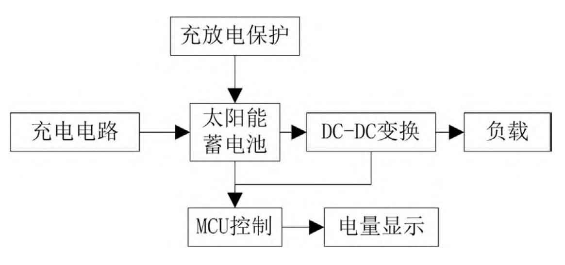
To improve the convenience of photovoltaic power supply, a portable photovoltaic mobile power supply is attempted to be designed based on the introduction of maximum power point tracking algorithm. The overall structure of the power supply includes charging circuit, charging and discharging protection, DC-DC conversion circuit, etc. Figure 1 is a schematic diagram of the overall structure of a portable photovoltaic mobile power supply. In the structure of portable photovoltaic mobile power supply, its charging circuit is mainly used to charge the battery. The application of solar panels makes the power supply more suitable for outdoor charging environments, and the mains power can also be charged indoors in low light conditions, effectively avoiding the problem of the power supply being unable to charge in continuous cloudy and rainy weather. In addition, the main function of the DC-DC conversion circuit in this power supply structure is to increase the voltage in the battery to 5V, providing the required charging voltage for electronic products.
After clarifying the overall structure of the power supply, provide selection and design instructions for each component in the structure. Firstly, select the solar cell components in the power supply. In solar cells, the voltage of the individual cells that make up the battery pack can only vary within the range of 0.45V~0.5V, while under normal circumstances, the current position is within the range of 20mA~25mA, and the power supply requirements for power operation cannot be met through the individual cells. Therefore, to address this issue, it is necessary to connect all individual cells in series to form a complete solar panel, in order to enhance the output power of portable photovoltaic mobile power sources and fully meet the functional requirements of the power supply. Based on the above analysis, the ZD92 * 55-490 high-quality PET pressure solar panel is selected as the solar cell module in the portable photovoltaic mobile power supply in this article. The open circuit voltage of this solar panel model is 6.4V, the maximum short circuit current is 120mA, the working voltage is 5V, the maximum working current is 100mA, and the maximum power is 0.9W; Size is 115mm * 51mm (length × Wide, it can be fully applied to portable electronic products. Meanwhile, the solar panels selected in this article contain various advanced materials such as Sunpower, single crystal, and polycrystalline silicon, and a diode structure is installed on the bypass to ensure that the overall power supply is not affected during operation and avoid heat spot loss. The surface of the battery panel also adopts a PET/PTFE packaging structure, which can effectively reduce the reflection of sunlight and improve optical transmittance, thereby promoting the improvement of the conversion efficiency of the entire portable photovoltaic mobile power supply. The service life of this model of solar panel exceeds 5 years, and the attenuation is less than 20%, which can further improve the level of power supply usage.
After completing the selection of solar cell components in the power supply, select the type of battery in the power supply. The HD468-4064 model 3.7V2400mAh lithium-ion battery is used as the built-in battery of the power supply in this article, with a rated capacity of 2400mAh. In theory, it can provide two fully charged conditions for electronic devices with a capacity of 1200mAh. The internal resistance of HD468-4064 lithium-ion batteries is 120m Ω; Weight is 30g; The storage temperature is within the range of -22 ℃ to+30 ℃; The cut-off voltage for charging is 4.2V; The charging current is 0.2C~0.5C; The factory voltage is 3.6V; Complies with the national GB31241-2014 battery cell standard. The HD468-4064 lithium-ion battery model itself has functions such as overcharge protection, over discharge protection, over-current protection, short circuit protection, etc. Therefore, applying it to the portable photovoltaic mobile power supply in this article can provide more favorable conditions for its operation reliability and safety. In practical applications, if the HD468-4064 lithium-ion battery needs to be stored for a long time, it should be charged to 50% of its capacity, with a voltage of about 3.8V, and placed in a reasonable storage environment. At the same time, for HD468-4064 lithium-ion batteries, it is necessary to complete a complete charging and discharging cycle at least once every 6 months to ensure the battery’s operational performance.
Finally, a selection and design explanation will be provided for the MCU control chip in the portable photovoltaic mobile power supply in this article. Based on the usage requirements of the power supply in this article, we have chosen the HT46R052B microcontroller of the HOLT9491-4690 model as the MCU control chip for the power supply. This model of microcontroller has a high-performance streamlined instruction set, and compared to other microcontrollers with similar functions, it has advantages such as low power consumption and flexible I/O conversion. The current HT46R052B microcontroller is widely used in industrial production, household appliances and other fields to achieve operational control. After completing the selection of MCU control chips, it is necessary to correspond their pin functions and determine the names, functions, and specific instructions of each pin according to Table 1.
| Number | Pin | Function Description |
| (1) | PA0, PN0 | Universal I/O interface A/D channel 0 |
| (2) | PA1, PA5 | External interrupt input universal I/O interface |
| (3) | PA2, PA3 | PWM output external timer input interface |
| (4) | PA4 A/D | Channel 1 |
| (5) | PA6, PA8 | A/D channel 2 Universal I/O interface |
| (6) | PA7, PA9 | Oscillator input pin Universal I/O interface |
| (7) | PA10 A/D | Channel 3 |
When the MCU control chip is running normally and there is no load situation, its working current is around 1.5mA. When the MCU control chip enters sleep mode, its working current will be lower than 10 μ A. Therefore, when the portable photovoltaic mobile power supply designed in this article is not applicable, it should be put into sleep mode by controlling the MCU control chip to avoid resource waste. When the MCU control chip enters sleep mode, it can be awakened through the following methods. Firstly, it can be directly awakened through an external reset port, and secondly, it can be awakened through external interrupts and PA port descent. When the MCU control chip is awakened from sleep mode, a certain delay time is required to restore to normal operating state. Therefore, in the subsequent setting of the operating program for portable photovoltaic mobile power supply, a delay program needs to be added.
1.2 Internal circuit structure design of power supply based on maximum power point tracking algorithm
On the basis of the overall structure design of the power supply mentioned above, the maximum power point tracking algorithm is introduced to optimize the internal circuit structure of the power supply. Due to the susceptibility of the solar battery inside the power supply to the surrounding environment, and the correlation between its output power and its own output voltage during operation, when the output power curve stabilizes at a certain node, that node is the maximum power point. Based on this characteristic, design the internal circuit structure of the power supply. When the power supply is under load or the internal resistance of the power supply is equal, its load can obtain the maximum power, but at this time, the internal resistance of the portable photovoltaic mobile power supply will also change with changes in light intensity and environmental temperature, so the optimal load size cannot be determined at this time. Therefore, in response to this issue, an attempt is made to add a Boost conversion circuit between the internal solar battery and the load, and combine PWM modulation technology to achieve overall control of the circuit and drive control of the internal circuit of the power supply, thereby achieving tracking of the maximum power output point of the power supply. Figure 2 shows the internal circuit structure of the power supply in this article.
In the internal circuit structure of the power supply shown in Figure 2, by changing the duty cycle of the switch, the output voltage of the portable photovoltaic mobile power supply can be adjusted to achieve the effect of the Maximum Power Point Tracking (MPPT) control algorithm. In this process, for the convenience of analysis, the change in the switch duty cycle can be regarded as the change in its step size. The calculation formula for the duty cycle is:
δ= T/T
In the formula, δ Represented as the change in the duty cycle of the switch; T represents the conduction time of the switching tube in the power supply; T represents the on/off time. On the basis of the above formula, determine the relationship between the input voltage and output voltage of the portable photovoltaic mobile power supply, as shown in the formula:
U0=(1/1-δ)/U1
In the formula, U0 represents the output voltage of the portable photovoltaic mobile power supply; U1 represents the input voltage of a portable photovoltaic mobile power supply. Based on the above formula, determine the relationship between input voltage and output voltage, and use this as a basis to provide a basis for subsequent power output voltage and current control.
1.3 Output voltage and current control of portable photovoltaic mobile power supply
In order to further improve the operational stability of portable photovoltaic mobile power sources, the output voltage and current are controlled according to the actual operating status. Introduce an MPPT control algorithm logic that presents the control logic set in the form of a mathematical function through inference and transformation. Using this mathematical function, reflect the relationship between input and output variables of portable photovoltaic mobile power sources. Usually, when controlling its voltage and current, the error amount and the specific variation of the error are used as input variables for the mathematical function. After being judged by the MPPT control algorithm logic, the final output variable result is calculated. In the above discussion, the formula for calculating the error in the input variable is:
e = p(n)-p(n-1)/I(n)-I(n-1)
In the formula, e represents the error value in the input variable; P (n) represents the output power value of the portable photovoltaic mobile power source obtained at a certain time n; I (n) represents the output current value of the portable photovoltaic mobile power source obtained at a certain time n; P (n-1) represents the output power value of the portable photovoltaic mobile power source obtained in the previous moment; I (n-1) represents the output current value of the portable photovoltaic mobile power source obtained in the previous moment. The value of the error variation in the input variable can be calculated using the following formula:
E0=e (n) – e (n-1)
In the formula, e0 represents the value of the error variation in the input variable; E (n) represents the output error of the portable photovoltaic mobile power source obtained at a certain time n; E (n-1) represents the output error of the portable photovoltaic mobile power source obtained in the previous moment. On the basis of the above formula, if the maximum power point of the portable photovoltaic mobile power supply during operation in practical applications is 0, then further analysis can be conducted through the MPPT control algorithm logic, and the value of the error change is also 0.
According to the above discussion, add a controller to the internal structure of the power supply based on the data results calculated by the formula. The input quantity of the controller is determined as the calculation result of the above formula. The control objective is to achieve the maximum power output of the power supply, so the output of the controller should be the output power value when the error change is 0. After clarifying the input and output, construct an MPPT control algorithm logic. The basic idea is to select a larger step size to control the duty cycle of the internal Boost circuit of the power supply designed above when it is farthest from the maximum power point; When it is closest to the maximum power point, a smaller step size can be used to control the duty cycle of the internal Boost circuit of the power supply. Based on the above control logic, it is ensured that the final portable photovoltaic mobile power supply can achieve maximum power output and improve the application performance of the portable photovoltaic mobile power supply by controlling the current and voltage.
1.4 Portable photovoltaic mobile power supply charging and discharging program and indicator light design
After completing the design of output voltage and current control for portable photovoltaic mobile power supply, it is necessary to clarify the program for charging and discharging the power supply, and design the indicator light display accordingly. The charging process of portable photovoltaic mobile power supply is divided into two stages, with the first stage being constant current charging. At this time, the charging voltage can reach a stable state and the value will not change. After reaching a certain threshold, the power supply enters the second state of constant voltage charging, and the charging current will gradually decrease over time. When the charging current gradually decreases to 0.1mA, it is considered that the portable photovoltaic mobile power supply has been charged to over 95% of its rated capacity, and it can be considered that the portable photovoltaic mobile power supply is basically fully charged. If it continues to be charged, the current will gradually decrease until it reaches 0, at which point the portable photovoltaic mobile power supply is fully charged. During this process, the charging indicator light remains on. When the power supply is in a fully charged state, the full charge indicator light is on and the charging indicator light is off. In order to better distinguish between the two types of indicator lights, the indicator light in the charging state lights up in red, and the indicator light in the fully charged state lights up in green.
The portable photovoltaic mobile power supply designed in this article is equipped with a solar battery inside, which can be used to charge external batteries and can also be directly used for external electronic devices. Therefore, in order to ensure higher stability of portable photovoltaic mobile power supply during operation, corresponding overcurrent protection is set for both power supply functions to ensure safe operation of the power supply. In the specific overcurrent protection, the HT46R052B microcontroller selected in this article is used to collect the discharge current and overcurrent protection information of the solar battery, and the MPPT control algorithm is used to control the on/off of the front-end solar battery charging circuit, thereby achieving the purpose of overcurrent protection.
2. Comparative experiment
On the basis of the above discussion in this article, in order to verify the feasibility of the portable photovoltaic mobile power supply design scheme based on maximum power point tracking algorithm, the development of portable photovoltaic mobile power supply is completed according to the above ideas in this article, and it is applied to real operating environments, Compare the performance of the portable photovoltaic mobile power supply designed by this design scheme with the traditional portable photovoltaic mobile power supply based on fuzzy control in application. Set the portable photovoltaic mobile power supply based on maximum power point tracking algorithm proposed in this article as the experimental group, and the portable photovoltaic mobile power supply based on fuzzy control as the control group. Test the performance of two types of portable photovoltaic mobile power sources under no light conditions and with light conditions, respectively.
2.1 Comparison of dark characteristics
Firstly, compare the dark characteristics of two portable photovoltaic mobile power sources. In the absence of light, two portable photovoltaic mobile power sources were placed in environments of 25 ℃ and 12 ℃. The voltage and current changes during the operation of the two power sources were investigated, and the results were recorded as shown in Table 2.
| No light at 25 ℃ environment | No light at 25 ℃ environment | No light at 25 ℃ environment | No light at 12 ℃ environment | No light at 12 ℃ environment | No light at 12 ℃ environment |
| Voltage | Experimental group current | Control group current | Voltage | Experimental group current | Control group current |
| 3.2V | 0.16mA | 0.10mA | 3.2V | 0.21mA | 0.11mA |
| 3.7V | 0.17mA | 0.13mA | 3.7V | 0.22mA | 0.14mA |
| 4.2V | 0.19mA | 0.16mA | 4.2V | 0.24mA | 0.17mA |
| 4.7V | 0.21mA | 0.20mA | 4.7V | 0.25mA | 0.22mA |
| 5.2V | 0.22mA | 0.20mA | 5.2V | 0.27mA | 0.23mA |
| 5.7V | 0.24mA | 0.22mA | 5.7V | 0.30mA | 0.25mA |
| 6.2V | 0.26mA | 0.24mA | 6.2V | 0.31mA | 0.27mA |
From the data recorded in Table 2, it can be seen that under no light conditions, the current of the portable photovoltaic mobile power supply in the experimental group showed a steady upward trend with the increase of voltage in a 25 ℃ environment and a 12 ℃ environment. The larger the voltage, the greater the current. The current of the portable photovoltaic mobile power supply in the control group showed an upward trend with the increase of voltage, but the increase in current was relatively small with the increase of voltage. From the recorded data above, it can be seen that during the operation of the two portable photovoltaic mobile power sources, the voltage and current variation curves of the experimental group power supply conform to the voltage and current variation law in the dark characteristics, while the control group power supply does not meet this characteristic. Through the above preliminary proof, the portable photovoltaic mobile power supply of the experimental group can achieve power supply under no light conditions in practical applications, and can ensure the stability of power supply, solving the problem that traditional portable photovoltaic mobile power supplies based on fuzzy control cannot supply power under no light conditions.
2.2 Circuit performance and charging comparison
Based on the above discussion in this article, after comparing the dark characteristics of two portable photovoltaic mobile power sources, the charging conditions of the two power sources were compared under normal lighting conditions, in order to achieve the performance inspection of the portable photovoltaic mobile power supply circuit. In order to ensure the objectivity of the experimental results, the same conditions were set for the two portable photovoltaic mobile power supplies: first, the two portable photovoltaic mobile power supplies were fully charged through charging and discharging equipment, and then discharged for 0.5Ah. Finally, the two portable photovoltaic mobile power supplies were placed in a cloudy weather environment for photovoltaic charging tests (time from 7:30 am to 13:30 am, illumination between 4300lx and 129000 lx), The charging adopts a variable current and constant voltage mode. During the constant voltage charging (5V) stage, the charging is set to end when the charging current is less than or equal to 50mA. The experimental data records are shown in Table 3.
| Portable photovoltaic mobile power supply for experimental group | Portable photovoltaic mobile power supply for experimental group | Control group portable photovoltaic mobile power supply | Control group portable photovoltaic mobile power supply | |
| Time | Current and voltage | LED display light | Current and voltage | LED display light |
| 7: 30 | 7: 30 65.2mA 4.60V red 62.6mA 4.60V red | Red | 62.6mA 4.60V | Red |
| 8: 30 | 89.1mA 4.66V | Red | 77.7mA 4.64V | Red |
| 9: 30 | 105.6mA 4.75V | Red | 92.6mA 4.71V | Red |
| 10: 30 | 117.3mA 4.82V | Red | 105.9mA 4.79V | Red |
| 11: 30 | 142.5mA 4.94V | Red | 121.3mA 4.83V | Red |
| 12: 30 | 160.2mA 5.0V | Red | 133.5mA 4.90V | Red |
| 13: 30 | 50.0mA 5.0V | Green | 97.2MA 5.0V | Red |
Based on the data in Table 3, it can be further concluded that during the charging process of two portable photovoltaic mobile power sources, the experimental group’s power supply current reached 50.0mA at 13:30 between 7:30 and 13:30, completing the charging process. However, the control group’s power supply only decreased to 97.2mA at 13:30, still in a constant voltage charging state, and did not complete the charging. Therefore, from this set of data, it can be seen that under the same environmental conditions, the experimental group has a larger charging current and a faster voltage rise, and the experimental group completed charging more quickly. Therefore, at 13:30, the display light was green. The charging current of the control group’s power supply was significantly lower, the voltage increased relatively slowly, and the charging time was also longer. Therefore, the final charging results proved that the charging efficiency of the experimental group’s portable photovoltaic mobile power supply was higher during the charging process. Based on the experimental results of the dark characteristics of portable photovoltaic mobile power sources at different temperatures under no light conditions and the operation of the power supply during charging, the proposed portable photovoltaic mobile power source based on maximum power point tracking algorithm has stronger operational stability and higher charging efficiency in practical applications. Compared with fuzzy control portable photovoltaic mobile power supply, it has better performance in various applications.
3. Conclusion
Currently, portable photovoltaic mobile power sources have been regarded as a new green and environmentally friendly energy source. In order to provide more convenient power supply conditions to more electronic devices, this paper proposes a new design concept for portable photovoltaic mobile power sources based on the introduction of maximum power point tracking algorithm. The feasibility of the application of this power source and its advantages compared to other power sources have been verified through experimental testing. However, during the research process, the relationship between battery discharge and temperature in portable photovoltaic mobile power sources was not taken into account, so there may be problems in ensuring the highest power supply efficiency in practical applications of portable photovoltaic mobile power sources. Therefore, in subsequent research, more in-depth research will be conducted on this issue, and reasonable and efficient compensation strategies will be attempted to promote the further improvement of the application adaptability of portable photovoltaic mobile power sources.