
The rapid development of photovoltaic (PV) systems has transformed modern building energy strategies. This article explores critical design principles, component selection, and optimization methods for solar power systems, emphasizing the role of solar inverters in energy conversion and grid integration.
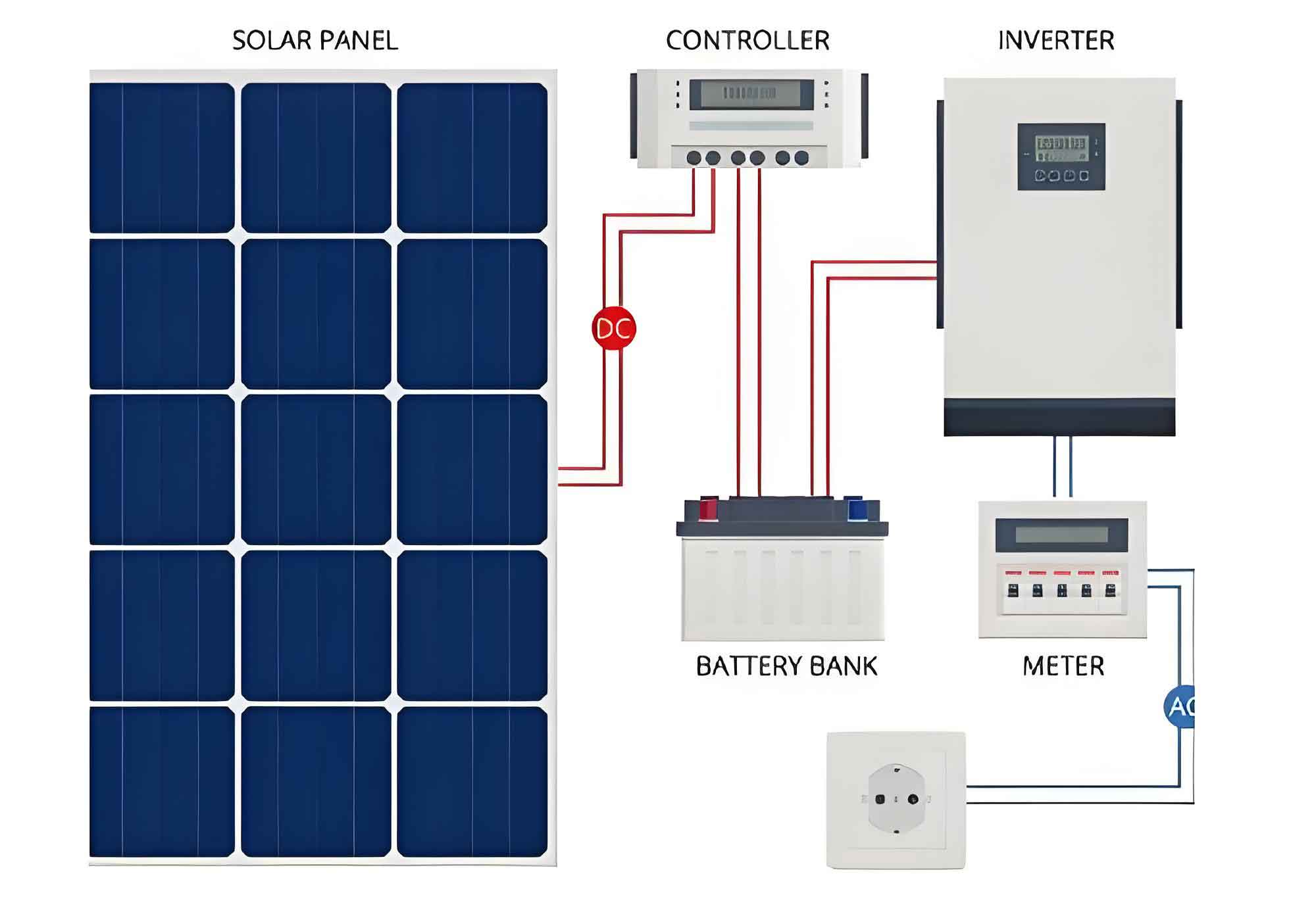
1. Core Components of PV Systems
| Component | Function | Key Parameters |
|---|---|---|
| Solar Modules | Convert sunlight to DC power | Efficiency (15-22%), Temperature Coefficient (-0.3%/°C) |
| Combiner Box | Aggregate module outputs | IP Rating (≥IP54), Maximum Input Strings |
| Solar Inverter | DC-AC conversion & grid synchronization | MPPT Range, THD (<3%), Efficiency (>97%) |
| Battery System | Energy storage (optional) | Depth of Discharge (80%), Cycle Life (>5,000) |
2. Fundamental Design Calculations
Annual Energy Yield:
$$ E_{annual} = G_{tilt} \times A_{array} \times \eta_{system} $$
Where:
$G_{tilt}$ = Solar irradiance on tilted surface (kWh/m²)
$A_{array}$ = Total module area (m²)
$\eta_{system}$ = System efficiency (0.65-0.85)
Battery Sizing:
$$ C_{bat} = \frac{E_{load} \times D_{autonomy}}{\eta_{inv} \times DoD} $$
Where:
$E_{load}$ = Daily load demand (kWh)
$D_{autonomy}$ = Required backup days
$\eta_{inv}$ = Solar inverter efficiency
$DoD$ = Battery depth of discharge
3. Solar Inverter Selection Criteria
| Parameter | String Inverter | Microinverter | Central Inverter |
|---|---|---|---|
| Power Range | 3-100 kW | 0.25-1 kW | 100 kW-1 MW+ |
| MPPT Channels | 2-4 | Per Module | Multiple |
| Efficiency | 97-98.5% | 94-96% | 98-99% |
| Typical Use | Residential/Commercial | Complex Roofs | Utility-scale |
4. Voltage Regulation and Grid Compliance
Modern solar inverters must maintain strict voltage parameters:
$$ \Delta V = \frac{P_{pv} \times R_{line}}{V_{grid}^2} \times 100\% $$
Where:
$P_{pv}$ = PV system output (kW)
$R_{line}$ = Line impedance (Ω)
$V_{grid}$ = Grid voltage (V)
Key compliance requirements:
– Voltage regulation: ±5% of nominal
– Frequency tolerance: ±0.5 Hz
– Harmonic distortion: THD <5%
5. Advanced System Monitoring
Smart solar inverters enable real-time performance tracking:
| Parameter | Sampling Rate | Accuracy |
|---|---|---|
| DC Voltage | 1 Hz | ±0.5% |
| AC Power | 1 Hz | ±1% |
| Irradiance | 5 min | ±5% |
| Module Temp | 5 min | ±1°C |
6. Fault Protection Mechanisms
Critical protection features in solar inverters:
$$ I_{fault} = \frac{V_{oc}}{Z_{string}} \times 1.25 $$
Where:
$V_{oc}$ = Open-circuit voltage
$Z_{string}$ = String impedance
- Anti-islanding protection (UL1741 compliant)
- DC arc fault detection
- Ground fault interruption
- Over-temperature shutdown
7. Emerging Technologies
Next-generation solar inverter capabilities:
$$ \eta_{inverter} = \frac{P_{out}}{P_{in}} \times 100\% – (a \times T_{ambient} + b) $$
Where:
$a$ = Temperature coefficient (0.03-0.07%/°C)
$b$ = Fixed losses (0.5-1.5%)
Advanced features:
– Hybrid solar inverters with battery integration
– Reactive power support (Q/V control)
– Cloud-connected predictive maintenance
– AI-driven maximum power point tracking
Through proper component selection and system design, modern photovoltaic installations can achieve 25+ year operational lifetimes with optimized energy yields. The solar inverter remains the critical intelligence hub, ensuring safe grid interaction and maximizing renewable energy utilization.