
As the global population continues to increase in the new century, the demand for energy for economic growth and development continues to expand. Global natural resources are gradually depleted, leading to the continuous rise of traditional energy prices. This has dragged down global economic growth and brought serious concerns of economic stagnation.
As a core component of photovoltaic power generation systems, photovoltaic inverters determine that the competition between domestic and foreign inverter manufacturers will inevitably be extremely fierce and cruel. Compared to traditional inverters, micro inverters have the characteristics of low reverse input voltage, high output voltage, and low power. In order to make products more competitive in the market, micro inverters need to be designed with full consideration of performance characteristics such as high conversion efficiency, high reliability, long lifespan, small size, and low cost.
The United States and Japan also have strong competitiveness in the photovoltaic power generation system industry due to their strong capabilities in circuit design, electrical, and automatic control fields, as well as their strong industrial foundation and advanced semiconductor technology; Although domestic enterprises are basically on par with foreign companies in terms of small capacity inverter technology, there is still a significant gap in the technical level of large capacity inverters, especially in large capacity grid connected inverters, mainly reflected in the reliability, efficiency, processing technology, standardized and modular design of the system.
Using micro inverters to optimize the solar system, independent micro inverters are equipped for the solar panels, improving the solar conversion efficiency of individual panels while also meeting the requirements of different weather and other environments. The characteristics of traditional inverters and micro inverters were compared, and the key technologies of micro inverters were studied. Comparing various possible hardware topologies, based on the performance characteristics of small size, high efficiency, and low cost of micro inverters, mathematical modeling and simulation were conducted on photovoltaic cells and micro inverter systems to verify the correctness of the design.
1. Micro inverter system and key technologies
Transforming the variable DC voltage input of the power supply into a non-interference AC sine wave output is the main function of the inverter, which can provide power to the corresponding equipment and feedback to the power grid. In addition to converting AC and DC voltage, the inverter can also perform tasks such as disconnecting the circuit to avoid current surges damaging the circuit. In addition, there are functions such as tracking maximum power point (MPPT), storing data, and controlling battery charging and discharging, all of which contribute to improving power generation efficiency.
1.1 Structure and characteristics of micro inverter system
1.1.1 Structure and characteristics of traditional inverters
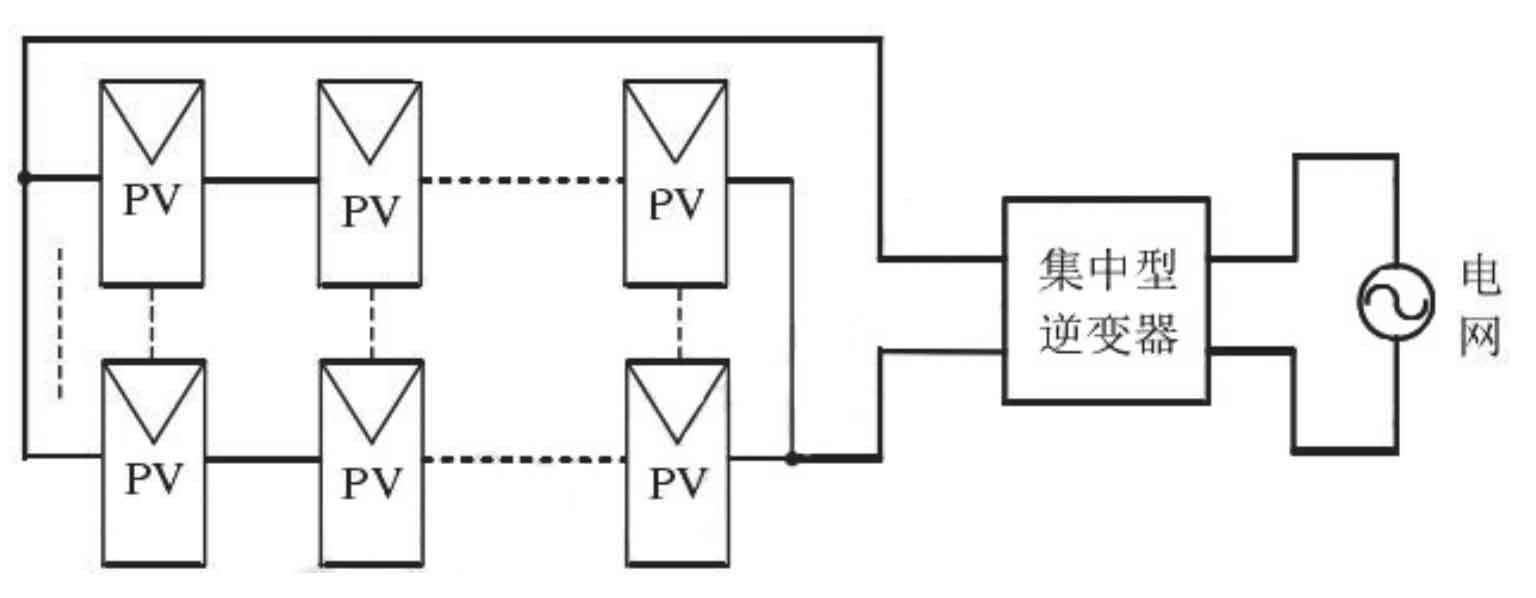
Traditional photovoltaic grid connected power generation systems typically achieve sufficiently high output power and DC voltage by connecting multiple photovoltaic cells in series and parallel, and then using a centralized grid connected inverter to feed energy into the grid. The structure is shown in Figure 1.
1.1.2 Structure and characteristics of micro inverters
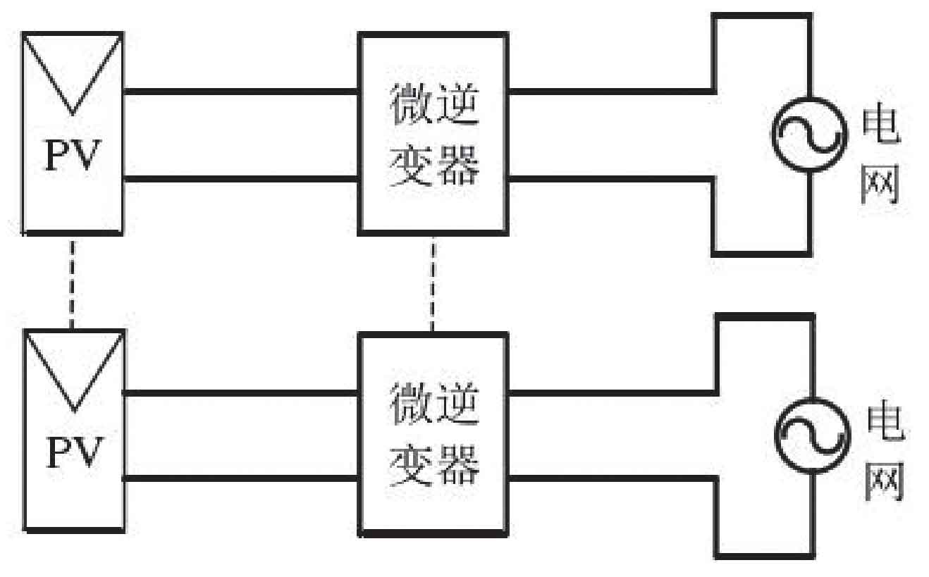
In order to overcome the above shortcomings, a photovoltaic grid connected structure based on micro inverters has been developed in recent years, as shown in Figure 2.
1.2 Advantages of Micro Inverters
Compared with traditional high-power centralized inverters, micro inverters have many advantages:
1) Ensure the maximum power point operation of each photovoltaic module. In practical applications, when there are changes in internal and external conditions such as cloud and mist changes, shadow occlusion, aging of photovoltaic modules, and accumulation of dirt, the total amount of power generated by using micro inverters can be increased by up to 25%.
2) In traditional photovoltaic systems, solar panels do not need to be connected in series with diodes, and the power loss between photovoltaic modules caused by series and parallel connection is eliminated.
3) The smaller power carrying capacity of micro inverters ensures higher product reliability, while traditional centralized inverters only have a 5-year operating life.
4) The system has high redundancy, and the failure of a single module will not affect the entire system. The failure of a micro inverter will not have an impact on other power generation units, and the impact will be very small.
5) As a whole, photovoltaic cells and micro inverters reduce the application difficulty of photovoltaic grid connected systems, and have the advantages of convenient expansion, plug and play, high flexibility, and easy promotion in the civilian market.
6) The installation is very convenient and the wiring is simple, greatly reducing the time and cost of installation and maintenance. Based on the above advantages, micro inverters have become a key focus in the photovoltaic industry and are considered one of the main structural forms for future photovoltaic applications. This project is based on this background and conducts in-depth analysis and research on the key technical issues currently existing in micro inverters, in order to provide high efficiency, low cost, and long service life micro inverter solutions, providing theoretical basis and practical reference for the marketization of micro inverter photovoltaic grid connected power generation systems.
1.3 Overview of Key Technologies of Solar Microinverters
1.3.1 Maximum power point tracking technology
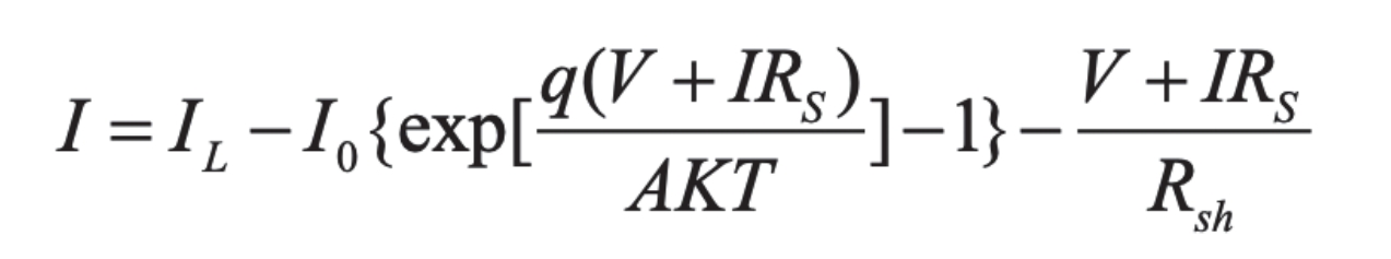
A simple PN junction can be used to illustrate the basic characteristics of solar cells made using the photovoltaic effect of semiconductor materials, where the reverse current of the PN junction is in the same direction as the current generated by illumination. According to electronic theory, the I-V characteristics of solar cells with ideal PN junctions are shown in the formula:
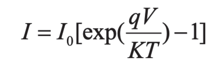
In the formula, I is the current of the PN junction, I0 is the reverse saturation current, V is the applied voltage, q is the electronic charge, K is the Boltzmann constant, and T is the absolute temperature. The base and top layers inevitably introduce additional resistance due to the material’s inherent resistivity, and the current flowing through them causes losses. In an equivalent circuit, the total effect can be represented by a series resistor Rs, a parallel resistor Rsh, and a PN junction capacitor. Therefore, the equivalent circuit of a solar cell can be represented in Figure 3.
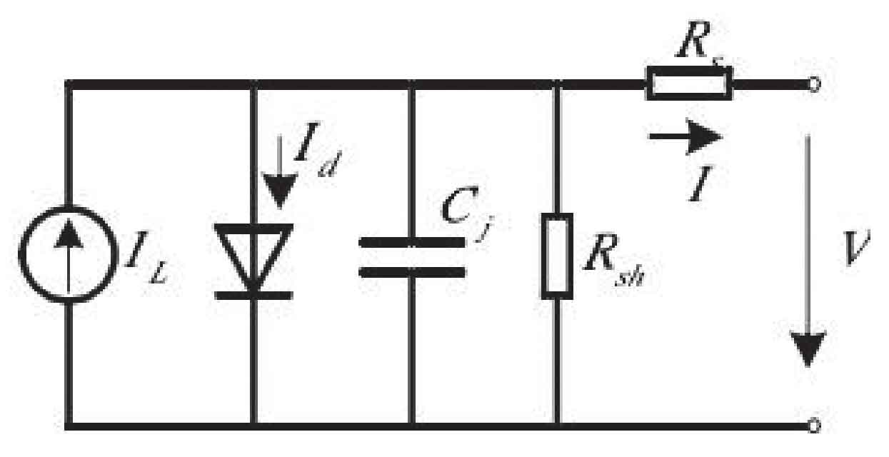
To describe the working state of a battery, an equivalent circuit is commonly used to simulate the battery and load system. Under constant illumination, a working solar cell’s photocurrent is independent of its operating state and can be used as a constant current source in an equivalent circuit. The parameters of solar cells in practical systems are distributed parameters, but they are still treated as concentrated parameters in engineering applications. Ignoring the influence of junction capacitance Cj, the I-V equation of a unit solar cell can be expressed as:
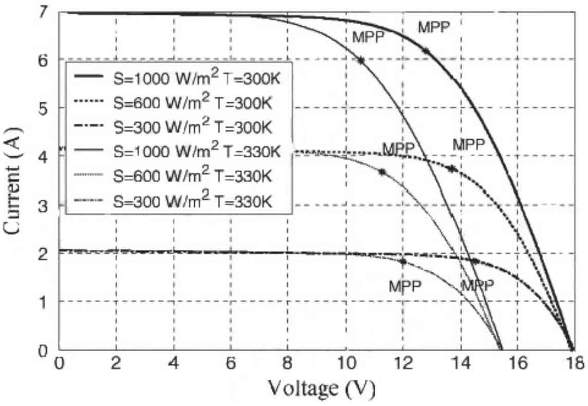
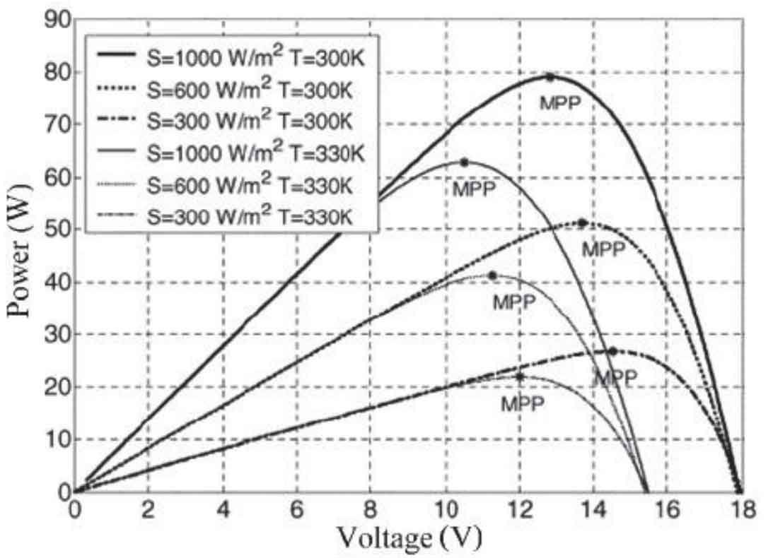
The relationship between the output current and output voltage of solar cells under determined sunlight intensity and temperature conditions is the I-V characteristics of solar cells, as shown in Figure 4. The I-V characteristic curve indicates that solar cells are neither constant current nor constant voltage sources, and they are a nonlinear DC power source. It is impossible to provide any large power to the load, and its output current is relatively constant in most working voltage ranges. The final current quickly drops to zero after exceeding a certain voltage. Figure 5 shows the output power voltage curve of the photovoltaic cell, abbreviated as the P-V curve. From the graph, it can be seen that each curve has a maximum power point under different lighting conditions, which uniquely corresponds to the battery output voltage. Therefore, the maximum power point is generally tracked by adjusting the output voltage of the photovoltaic cell to approach the maximum power point.
According to the formula, factors such as battery junction temperature and sunlight intensity affect the output characteristics of solar cells. When other conditions are determined, the short-circuit current Isc increases almost proportionally to the sunlight intensity, while the open-circuit voltage Voc of the solar cell slightly increases in a logarithmic relationship with the increase of sunlight intensity. The output power of solar cells decreases with the decrease of sunlight intensity. In addition, when other conditions are determined, the open circuit voltage Voc of the solar cell will decrease as the battery junction temperature increases, while the short circuit current Isc will slightly increase. Overall, the output power of solar cells decreases as the junction temperature increases, while sunlight intensity and ambient temperature affect the junction temperature of solar cells.
1.3.2 Grid connected current control technology
In terms of grid connected current control in photovoltaic systems, existing control methods include double loop control, hysteresis control, deadbeat control, space vector PWM control (SVPWM), peak current control, and repetitive control. Double loop control uses current and voltage loop control to stabilize DC voltage and adjust the amplitude of grid connected current. Double loop control is easy to design for the system and has a fixed switching frequency. However, when the switching frequency is not high enough, the dynamic response of current is relatively slow, and the dynamic deviation of current changes accordingly with the change of current change rate.
1.3.3 Island detection technology
The islanding effect refers to the rapid self disconnection of photovoltaic grid connected power generation systems installed at various user terminals from the municipal power network when the power supply system of the power company stops working due to faults or power outage maintenance. Therefore, a self-sufficiency island phenomenon that cannot be mastered by the power company, which is powered by the photovoltaic grid connected power generation system to the surrounding loads, has emerged. The islanding effect is a unique phenomenon in grid connected power generation systems, which has significant harm. It not only endangers the entire distribution system and equipment at the user end, but also poses a threat to the life safety of transmission line maintenance personnel. The key to anti islanding effect lies in the detection of power grid outages. The shorter the detection time, the better, and it should meet international standards IEEE Std. 2000-929 and IEEE Std. 2003-1547. In March 2004, China established detailed regulations on anti islanding effects in the technical requirements for photovoltaic power generation grid connected systems formulated by the Energy Research Institute of the Ministry of Science and Technology. In addition to setting up over/under voltage protection and over/under frequency protection as backup protection against islanding effects, photovoltaic systems should also be equipped with at least one active and passive mode of anti islanding protection, And the anti islanding effect protection should act within 0.5s-1 seconds after the power grid is cut off to disconnect the photovoltaic system from the power grid. The anti islanding effect detection technology is mainly divided into active detection and passive detection on the grid connected inverter side.
2. Research on Microinverter Topology
2.1 Overview of Micro Inverter Topology
Micro inverters boost the low-voltage direct current on the PV side and then integrate it into the power frequency grid through inverter, so the selected topology must have a boost function. Generally, single-phase grid connected inverters use the front-end DC-DC to achieve maximum power tracking, while the back-end DC-AC achieves inverter grid connection. DC-DC and DC-AC both achieve MPPT algorithm, grid connection control, and protection functions such as overvoltage and islanding by controlling the switch off. The auxiliary power supply supplies power to the control system and various feedback sampling loops.
From the topology level of micro inverters, there are mainly two types: one is a DC-DC plus DC-AC two-stage structure, and the other is a DC-DC plus a cycle converter.
The two-stage micro inverter is controlled by the front stage for maximum power tracking, and the rear stage for grid connected current control. Traditional centralized grid connected inverters often use current closed-loop control to ensure that the grid connected current and grid voltage are in the same frequency and phase. Due to the fact that DC-DC and DC-AC can be controlled separately, the coupling between the front and rear stages is relatively low and can be designed separately. Therefore, the design of the control loop feedback loop is much easier than that of a single stage inverter, but the two-stage inverter will inevitably affect the overall efficiency due to the two-stage power conversion. If the efficiency of each stage is 90%, the efficiency from the PV input to the grid side through the two-stage is only 81%, which is unacceptable for high-efficiency micro inverters.
The front stage DC-DC of a single stage inverter achieves MPPT tracking, grid connected current closed-loop control, and electrical isolation, making the control complex. However, with the rapid development of digital chips, the single stage inverter is easy to achieve without affecting the stability and overall efficiency of the entire photovoltaic system. The single stage inverter has a simple structure, saves costs, and only has one stage of power conversion, reduces power loss, and reduces the cost of the entire micro inverter system. Moreover, after experimental verification, the single stage inverter is stable and reliable.
2.2 Working principle of flyback inverter
In various circuit topologies of DC-DC, flyback converters generally work in low-power applications. In high-frequency switching power supplies, flyback converters can achieve electrical isolation, energy transfer, storage, voltage rise and fall functions, and are widely used in low-power power supplies.
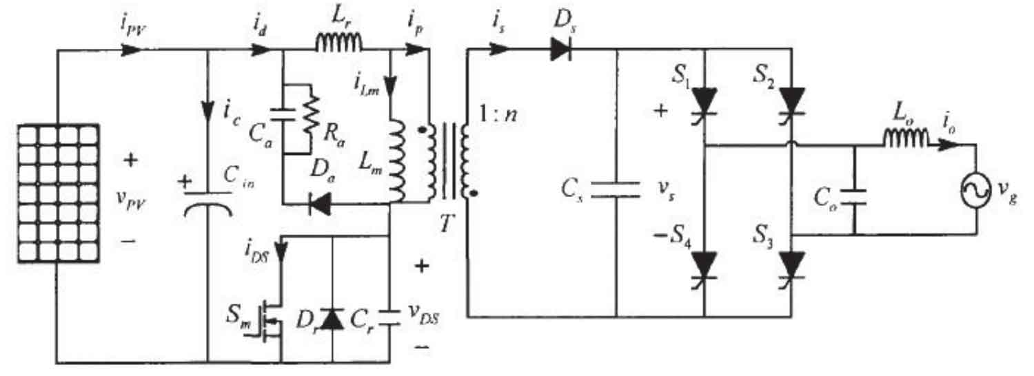
Due to the unstable DC bus voltage during the power decoupling process of the two-stage topology, it is easy to cause the inverter to not work, and the requirements for the control chip are high. Voltage source grid connected inverters using SPWM modulation usually use two-stage power conversion, and the switch operates in a high-frequency state, which increases switching losses. The flyback inverter topology adopted is used for power conversion in the front stage, while the power frequency inverter in the back stage only has conduction loss. Single stage power conversion not only reduces costs but also improves the efficiency of the entire system, making it very suitable for photovoltaic grid connected micro inverters that require low prices and superior performance.
3. Conclusion
Solar energy is undoubtedly the cleanest energy in the world, inexhaustible and inexhaustible. With the development of the world economy and the demand for energy, as well as the scarcity of energy and environmental degradation, photovoltaic power generation will inevitably become an important industry. How to efficiently utilize solar energy is closely related to the technology of micro inverters, the core device of photovoltaic power generation systems. Due to the dispersed nature of solar energy, The research on micro inverters will become a research focus.
Mainly analyzed and compared the topology structure of photovoltaic grid connected micro inverters, and optimized the design of solar systems using micro inverters. Each panel is equipped with a separate micro inverter for solar energy, allowing the system to adapt to constantly changing loads and weather conditions, thereby providing the best conversion efficiency for a single panel and the entire system.