
In recent years, the photovoltaic technology has experienced rapid development and has become a reliable and mature product. Most solar cells are made of crystalline silicon, with electrical efficiency typically below 20%. Studies have shown that among the solar radiation energy absorbed by a solar panel, less than 20% is converted into electricity, while the remaining portion is dissipated as heat, causing the panel temperature to rise. A higher operating temperature of the solar panel leads to an increase in internal resistance and a corresponding decrease in electrical efficiency. Specifically, the electrical efficiency drops by about 0.5% for every 10°C increase in panel temperature. In order to improve the performance of solar panels, many researchers have adopted cooling measures such as air cooling, water cooling, and in a few cases, refrigerant cooling where the panel is used as an evaporator in a heat pump system. However, most of these systems are active cooling systems that require additional electrical energy to drive the cooling process.
In this context, I focused on the thermal and electrical performance of solar panels under passive cooling conditions. The main research contents include: (1) attaching heat dissipation fins to the back of the solar panel and investigating the effects of panel inclination angle, solar radiation intensity, ambient temperature, wind velocity, fin height, and fin spacing on its electrical performance under natural ventilation conditions; (2) attaching heat pipes to the back of the panel and installing a header on top to form a heat-pipe solar photovoltaic water heater, and studying the effects of solar radiation intensity, inlet water temperature, and water circulation flow rate on electrical and thermal efficiencies. The study combines numerical simulation and experimental testing. Mathematical models were established and solved using Matlab, while experimental platforms were built to verify the simulated results.
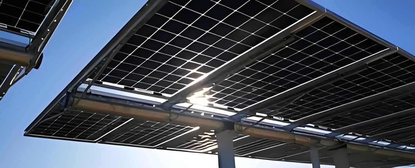
1. Research Background and Objectives
The global energy demand is expected to double by 2025 according to the International Energy Agency. Conventional energy reserves are depleting, making renewable energy sources such as solar energy increasingly important. Solar radiation reaching the Earth’s surface carries an enormous amount of energy; every second, the Earth receives energy equivalent to about 500 million barrels of oil. China has abundant solar resources, with more than 60% of its territory receiving good solar radiation. The efficient utilization of solar energy is therefore of great significance.
The primary goal of my research is to enhance the electrical performance of solar panels through passive cooling, which requires no additional electrical input. By attaching fins or heat pipes to the back of the panel, the heat generated during photovoltaic conversion can be removed naturally, thereby lowering the panel temperature and improving its efficiency. In addition, the heat recovered by the heat pipe system can be used to produce hot water, thus achieving combined photovoltaic/thermal (PV/T) utilization.
2. Numerical Models
2.1 Thermal Balance of a Solar Panel without Fins
For a bare solar panel, the energy balance equation can be written as:
$$ \alpha_p \tau_p Q A_p = E + h_{pa} A_{pa}(T_p – T_a) + h_{ep} A_{ep}(T_p – T_e) $$
where:
| Symbol | Meaning |
|---|---|
| \(Q\) | Solar radiation intensity (W/m²) |
| \(A_p\) | Area of the solar panel (m²) |
| \(\alpha_p \tau_p\) | Effective absorptance of the photovoltaic cell |
| \(E\) | Electrical output power (W) |
| \(h_{pa}\) | Convective heat transfer coefficient between panel and air (W/(m²·K)) |
| \(T_p\) | Panel temperature (K) |
| \(T_a\) | Ambient temperature (K) |
| \(T_e\) | Sky temperature (K) |
| \(h_{ep}\) | Radiative heat transfer coefficient between panel and sky (W/(m²·K)) |
The electrical output power \(E\) is expressed as:
$$ E = Q \tau_g \eta_{ref} [1 – \kappa (T_p – 298.15)] $$
where \(\eta_{ref}\) is the reference efficiency (15%) and \(\kappa\) is the temperature coefficient.
2.2 Thermal Balance of a Solar Panel with Fins
When fins are attached to the back, the energy balance includes heat conduction to the fins and natural convection from the fins. The governing equations for the panel, the back metal plate, the fins, and the air between fins are coupled. A representative equation for the panel is:
$$ \alpha_p \tau_p Q A_p = E + h_{pb} A_{pb}(T_p – T_b) + h_{pa} A_{pa}(T_p – T_a) + h_{ep} A_{ep}(T_p – T_e) $$
Similar equations are used for the back plate and the fins. The model accounts for fin geometry, thermal conductivity, and contact resistances.
2.3 Heat-Pipe Solar Photovoltaic Water Heater
The heat-pipe system exchanges heat with circulating water in a header. The energy balance for each component (panel, back plate, insulation layer, heat pipe wall, evaporator section, condenser section, and water) is established. The heat transfer from the condenser to water is given by:
$$ \dot{Q}_w = h_w A_w (T_{HP,c} – T_w) = \dot{m}_w c_w (T_{out} – T_{in}) $$
where \(\dot{m}_w\) is the water mass flow rate, \(c_w\) is the specific heat of water, and \(T_{in}\), \(T_{out}\) are the inlet and outlet water temperatures.
3. Experimental Setup
Experiments were conducted to validate the numerical simulations. For the natural cooling study, a polycrystalline silicon solar panel (YGE110 series, 1172 mm × 660 mm × 35 mm) was used. Heat dissipation fins were attached to the back of the panel. Thermocouples were installed at different positions to measure the panel temperature, an electric fan was used to control wind velocity, and a pyranometer was used to measure solar radiation. The panel output power was measured by connecting a known load resistance and recording the voltage across it.
For the heat-pipe solar photovoltaic water heater, a larger panel (YL200P-23b, 1310 mm × 990 mm × 40 mm) was equipped with 10 heat pipes spaced 75 mm apart. The condenser sections were inserted into a header through which water circulated. A pump, a rotameter, a storage tank, and an Agilent data logger were used to control and record the operating conditions.
4. Results and Discussion
4.1 Natural Cooling Performance
4.1.1 Effect of Panel Inclination Angle
Simulations were carried out for a solar radiation intensity of 800 W/m², wind velocity of 3 m/s, ambient temperature of 16°C, fin height of 0.1 m, and fin spacing of 0.08 m. The results show that as the inclination angle increases from 20° to 60°, the electrical efficiency first decreases and then slightly increases, with a minimum around 45°. The output power shows the opposite trend. The following table summarizes the average values obtained from simulation.
| Configuration | Average Electrical Efficiency (%) | Average Output Power (W) |
|---|---|---|
| Without fins | 14.36 | 115.2 |
| With fins | 14.63 | 117.4 |
Experimental results at a radiation intensity of 900±50 W/m², ambient temperature of 30±2°C, and wind speed of 1 m/s gave similar trends. The finned panel had an average efficiency of 10.97% while the bare panel had 10.17%, an improvement of 0.8 percentage points.
4.1.2 Effect of Wind Velocity
Increasing wind velocity enhances convective heat transfer and lowers the panel temperature, thus improving electrical efficiency. Simulation results show that when the wind speed increases from 3 m/s to 6 m/s, the efficiency of the finned panel rises from 14.64% to 14.87%, while the bare panel efficiency rises from 14.36% to 14.78%. The average improvement due to fins is about 0.17 percentage points.
4.1.3 Effect of Ambient Temperature
The electrical efficiency decreases linearly with increasing ambient temperature. Simulation results indicate that a 10°C increase in ambient temperature reduces the efficiency by approximately 0.68% for both configurations. Experimental data show reductions of 0.73% and 0.75% for the finned and bare panels respectively.
4.1.4 Effect of Solar Radiation Intensity
Experimental tests were conducted with radiation intensities from 284 W/m² to 685 W/m². Higher radiation increases the output power but also raises the panel temperature. The electrical efficiency of the finned panel increased from 4.67% to 10.41%, while the bare panel increased from 4.74% to 7.83%. The improvement in efficiency is more pronounced at higher radiation levels due to better heat dissipation with fins.
4.1.5 Effect of Fin Height and Fin Spacing
The simulation shows an optimal fin height where the efficiency reaches a maximum. This occurs because increasing fin height increases the heat transfer area but also reduces the convection effectiveness of the air between fins. For the given conditions, the optimal fin height was found to be around 86 mm. Fin spacing is inversely related to efficiency: smaller spacing yields more fins and better heat extraction, as shown in Table 3.
| Fin spacing (mm) | Electrical efficiency (%) – finned panel |
|---|---|
| 10 | 14.74 |
| 40 | 14.60 |
| 100 | 14.50 |
4.1.6 Daily Performance
During a typical sunny day, the electrical efficiency decreases from morning to noon and then increases in the afternoon, mirroring the variation of panel temperature. The output power peaks around noon. The average daily efficiency of the finned panel was found to be about 0.17–0.49 percentage points higher than that of the bare panel in simulations and experiments, respectively.
4.2 Heat-Pipe Solar Photovoltaic Water Heater
4.2.1 Temporal Variation of Thermal and Electrical Efficiencies
The thermal efficiency of the heat-pipe system decreases with time as the water temperature in the storage tank rises. In a representative day, the experimental thermal efficiency dropped from 17.32% at 9:00 to 2.56% at 13:30, with an average of 7.91%. The electrical efficiency first decreased, reached a minimum around noon, and then recovered. The average electrical efficiency was 12.88% in simulation and 11.90% in experiment.
4.2.2 Effect of Inlet Water Temperature
Increasing the inlet water temperature reduces the temperature difference between the condenser and the water, thus lowering the heat transfer rate and thermal efficiency. Simulation results show a linear decrease in thermal efficiency from 14.72% to 5.60% when the inlet water temperature rises from 20°C to 44°C. The electrical efficiency also decreases because the panel temperature rises. The experimental average efficiencies were 10.08% (thermal) and 12.89% (electrical) within the same range.
4.2.3 Effect of Solar Radiation Intensity
Higher solar radiation increases the heat available for water heating, resulting in a higher thermal efficiency, but it also increases the panel temperature and decreases the electrical efficiency. The following table presents the rates of change per 100 W/m² derived from simulation and experiment.
| Quantity | Simulation (% per 100 W/m²) | Experiment (% per 100 W/m²) |
|---|---|---|
| Thermal efficiency | +1.18 | +1.26 |
| Electrical efficiency | −0.23 | −0.99 |
4.2.4 Effect of Water Flow Rate
The experiments showed that increasing the circulation flow rate from 5 L/min to 9 L/min reduced both thermal and electrical efficiencies. The thermal efficiency dropped from 18.91% to 16.07%, while the electrical efficiency fell from 12.44% to 11.28%. This occurs because a higher flow rate reduces the residence time of water in the condenser, leading to less effective heat exchange even though the convective coefficient increases.
5. Conclusions
Based on the numerical and experimental studies, the following conclusions can be drawn:
- Attaching heat dissipation fins to the back of a solar panel improves its electrical performance. Under the tested conditions, the finned panel showed higher electrical efficiency and output power than the bare panel.
- The electrical efficiency of a solar panel first decreases and then increases with inclination angle, reaching a minimum at around 45° in Beijing. The output power has the opposite trend.
- Higher ambient temperature reduces the electrical efficiency linearly. A 10°C increase reduces efficiency by about 0.7% in both configurations.
- Increasing wind velocity improves heat dissipation and increases the electrical efficiency.
- There exists an optimal fin height for maximum electrical efficiency. Fin spacing should be as small as practically possible to improve performance.
- The heat-pipe solar photovoltaic water heater can effectively combine heat and power generation. The thermal efficiency decreases with time and with inlet water temperature, while it increases with solar radiation. The electrical efficiency decreases with higher radiation and higher inlet water temperature.
- For the heat-pipe system, a lower water flow rate results in higher thermal and electrical efficiencies under the tested range.
In summary, passive cooling is a promising approach to improve the performance of solar panels without additional energy consumption. The integration of heat pipes allows simultaneous production of electricity and hot water, making the system more efficient and economical in the long run.