
1. Overview of solar inverters
The photovoltaic inverter system is mainly composed of three parts as shown in Figure 1: solar panels, photovoltaic inverter, and load (power grid).We mainly study the solar inverter, which converts the small DC power generated by the solar panels into household 220V AC power to provide to the load.
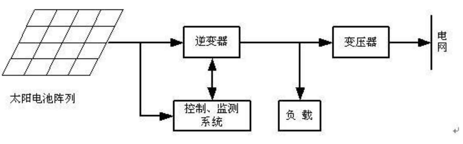
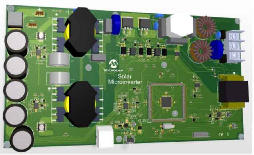
This article studies grid-connected devices and does not use batteries (no controller is required), so the solar inverter can be directly connected to the photovoltaic grid. The physical diagram of the solar inverter is shown in Figure 2.
The focus of this article is on one-way solar inverters, which include two main parts: hardware and software. The main chip TMS320F28035 sends out a series of control signals to control the various high and low level changes in the software part, thus controlling the actions of the hardware, such as the opening and closing of field effect transistors, the driving of gate circuits, and the opening and closing of various switches in the bridge circuit.In this process, a series of feedback signals formed by monitoring circuits are sent to the main chip, which finally determines whether the system is operating normally and takes corresponding actions, which are reflected in related devices (such as LED transistors).
2. Relevant technologies of single-phase solar inverters
2.1 Basic principles of solar inverters
The main theoretical basis for solar inverters to achieve inversion is the area equivalence principle and high-frequency modulation technology.The so-called area equivalence principle (impulse equivalence theorem) is that when narrow pulses with equal impulse (integral of variable against time) and different shapes are applied to the inertial link, their output response waveforms are basically the same, as shown in Figure 3.According to Fourier analysis, the output voltage contains only certain higher harmonics (many lower harmonics are eliminated) except for the fundamental wave. The more pulse wave numbers and the higher the switching frequency, the more lower harmonics can be eliminated.
High-frequency modulation technology mainly includes the following categories:
(1) Pulse frequency modulation: By changing the pulse frequency, the power factor angle of the load is changed to achieve the purpose of regulating the output power.
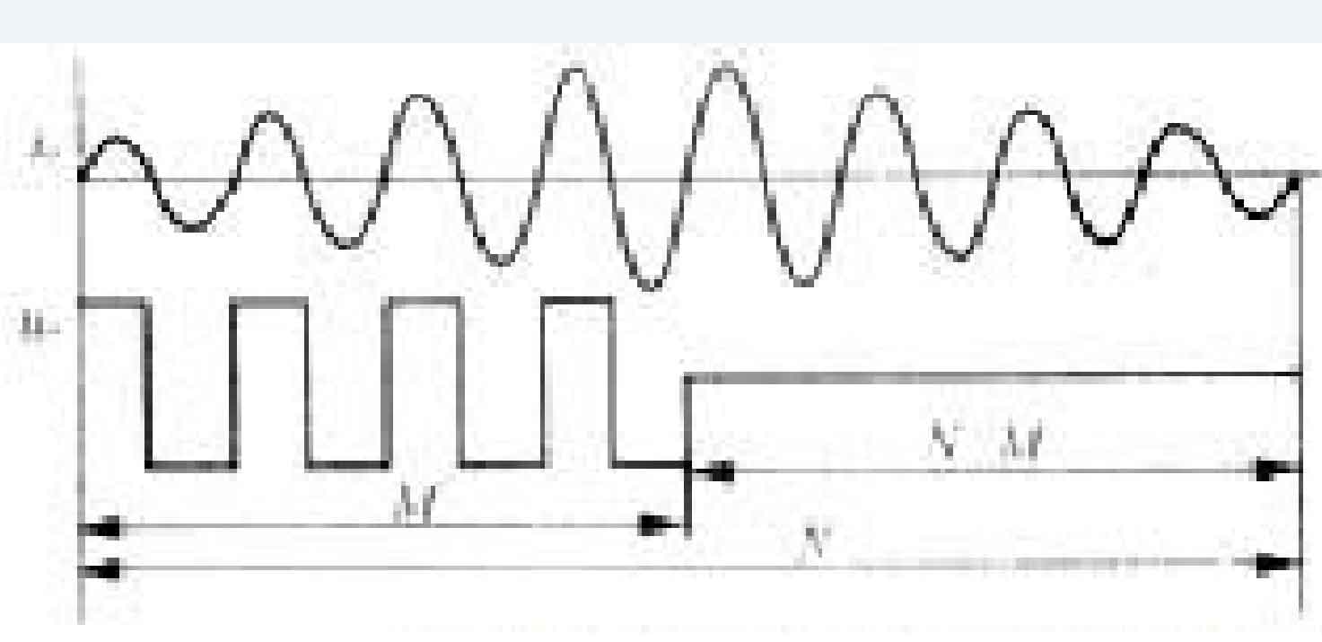
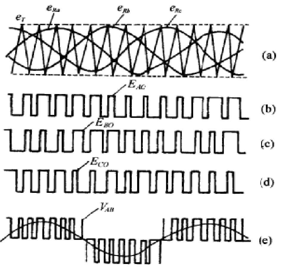
(2) Pulse density modulation: The output power is controlled by controlling the pulse density (the time to feed energy to the load), as shown in Figure 4.
(3) Pulse amplitude modulation: By changing the amplitude of the output voltage of the solar inverter, the output power can be controlled.
(4) Pulse width modulation: A method of using modulation signals to change the pulse width.Due to high transmission bandwidth, good input and output linearity, fixed carrier frequency, ease of filter parameter setting, and device selection, PWM technology is currently the most widely used high-frequency modulation technology.
2.2 Classification of solar inverters
The classification of solar inverters mainly includes the following types:
(1) According to the number of output phases of solar inverters: single-phase, three-phase, and multi-phase inverters.
(2) According to the control mode of solar inverter output: current-type solar inverter and voltage-type inverter.
(3) According to the different inputs of solar inverters: voltage source solar inverter and current source inverter.
(4) According to the direction of the output power flow of solar inverters, there are active solar inverters and passive inverters.
(5) Modulation methods of switches: unipolar PWM modulation solar inverter, bipolar PWM modulation solar inverter, square wave modulation solar inverter, step wave modulation solar inverter, and vector modulation and tracking modulation inverter.
This article mainly studies single-phase photovoltaic voltage-type solar inverters.
The output voltage of this solar inverter is 220V, which is suitable for residential use and requires no voltage reduction.Compared to current-mode solar inverters, voltage-mode solar inverters can operate stably even when an open-loop motor is subjected to overcurrent due to a load short circuit.Considering these characteristics, a single-phase photovoltaic grid-connected voltage-mode solar inverter is used in this article.
2.3 SPWM technology of single-phase solar inverter
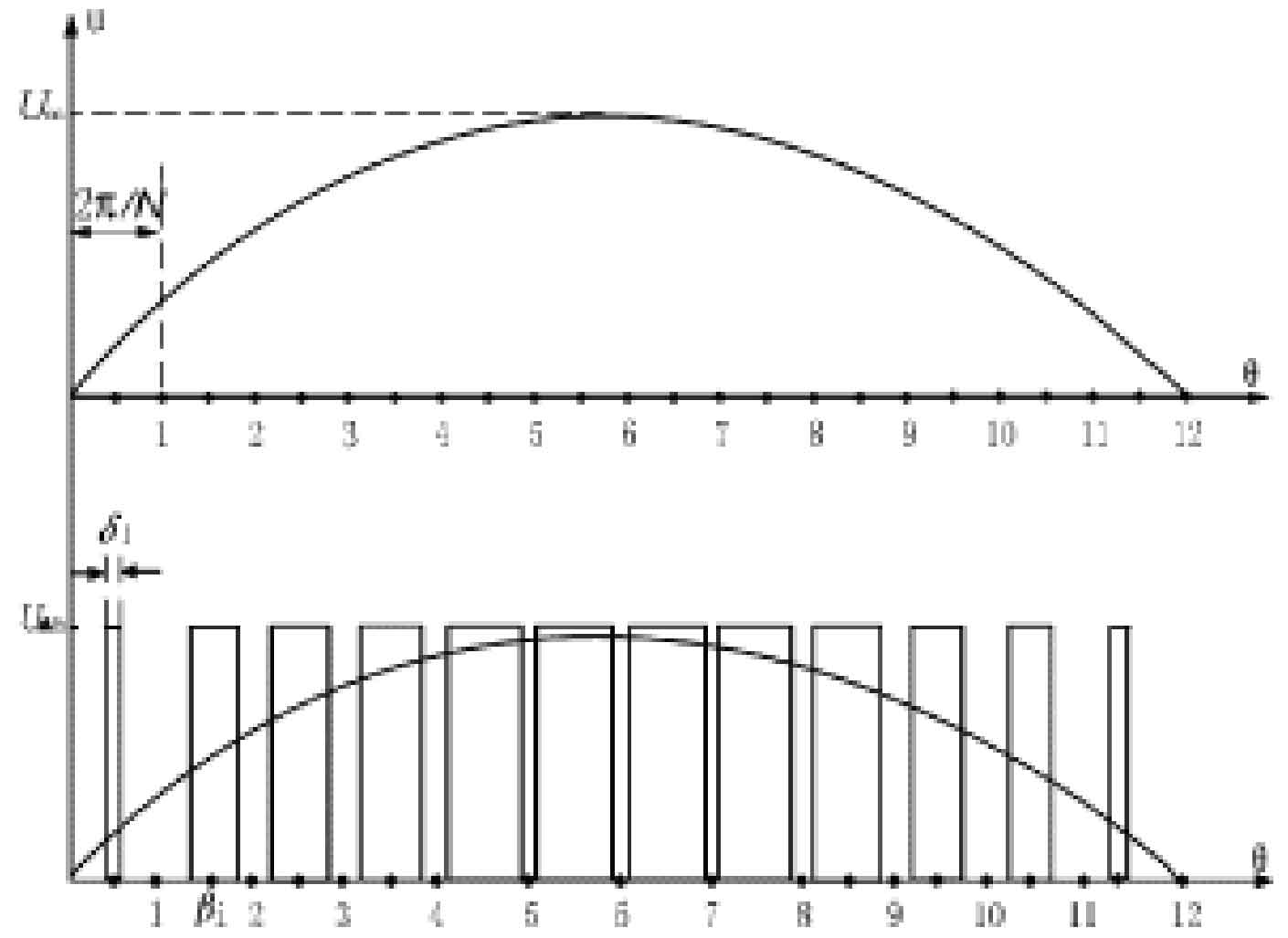
The fundamental and core theoretical basis of solar inverters is the sine-wave pulse width modulation (SPWM) technology.Here is an introduction to this technology:
As shown in Figure 3, N equal-width sine half-waves are connected by N equal-amplitude pulses with varying amplitude according to the sine law.If the pulse sequence is replaced by an equal number of equal-amplitude but unequal-width rectangular pulse sequences with equal impulse, this is the PWM waveform.According to the impulse equivalence principle, the PWM waveform and the sine waveform are equivalent.The negative half-cycle of the sine waveform can be obtained using the same method to obtain the PWM waveform, which is called SPWM, as shown in Figure 5.
3. Expected technical indicators
(1) Power level: 250W
(2) Isolation method from the power grid: transformer
(3) MPPT range: 20V-45V
(4) Open circuit voltage: 55V
(5) Maximum input current: 10A
(6) Maximum grid-connected current: 1.5A
(7) Grid voltage: 220V, requiring a grid voltage variation range of 210V-264V
(8) Input power: 250W
(9) Grid-connected power: 215W
(10) AC output power: 215W
(11) Output rated power: 50Hz, with a variation range of 49.8 Hz to 50.2 Hz
(12) Total current harmonic distortion rate THD<5%
4. Overall plan and key technologies of single-phase solar inverter
4.1 Overall plan of single-phase solar inverter
Based on the powerful digital signal processing capabilities of the TMS320F28035 chip from TI, the single-phase photovoltaic grid-connected controller has the advantages of low cost, high reliability, flexible design, and ease of miniaturization.The main function of this controller is to invert the DC power generated by the solar panel into household AC power through control circuits such as single-ended inverter and full bridge circuit.At the same time, through real-time monitoring devices such as overvoltage, overcurrent, undervoltage, and temperature sensors, various data in the circuit are fed back, and compared with the rated value to reflect the operating state of the circuit.When the circuit operates at the rated state, all the LED real-time monitoring lights go out, and when the system operates at the non-rated state, the LED lights will light up. The number of times the LED lights light up indicates the type of error.When the error is removed, the system will be restarted, and the LED lights will continue to light up for 1 minute, which is a visual representation of the last error.
4.2 Topological structure of the main circuit of a single-phase solar inverter
In addition to the necessary theoretical support, the implementation of inverting must also be supported by corresponding topology structures. This section mainly introduces the topology structure of the main circuit of solar inverters.Due to the disadvantages of expensive price, large volume, and difficult maintenance of power frequency transformers, high frequency inverter circuits are often used in practical applications.The solar inverters studied in this article can be divided into two parts: DC-DC and DC-AC.
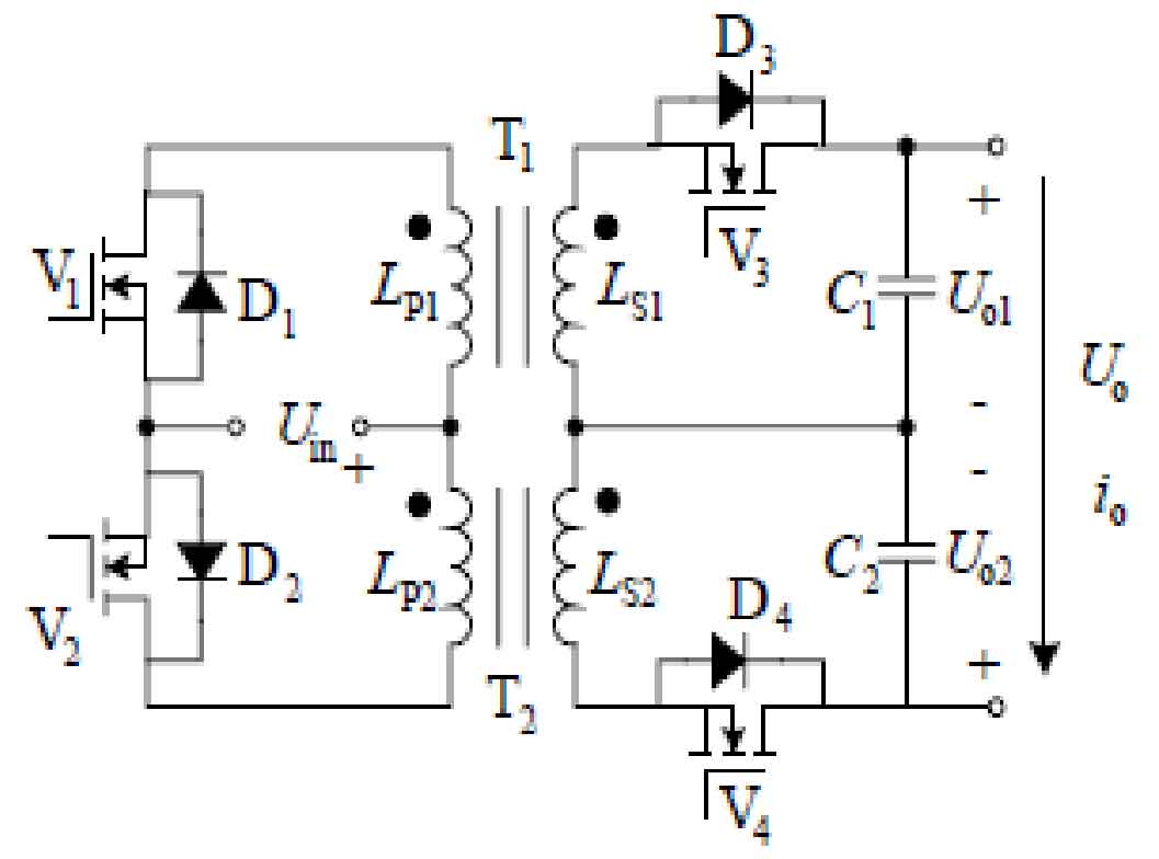
The function of the front-stage DC-DC converter is to convert the low-voltage DC output from the photovoltaic panel into the required high-voltage DC.Its topology includes the following three types: forward conversion, flyback conversion, and double-ended conversion.The so-called double-ended conversion is the transformer primary side topology (including half-bridge, full-bridge, and push-pull).This article uses a flyback push-pull circuit, whose circuit topology is shown in Figure 6:
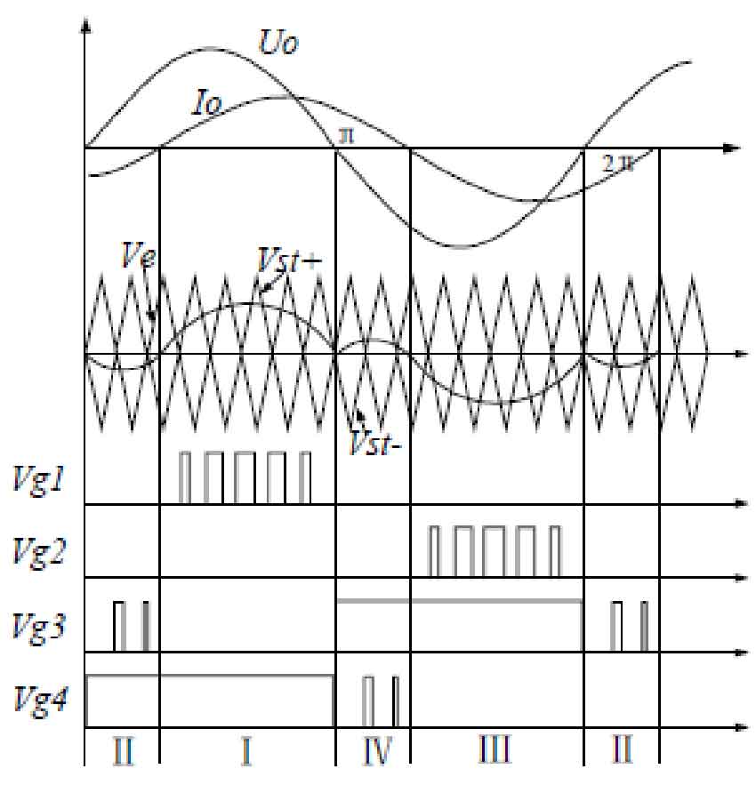
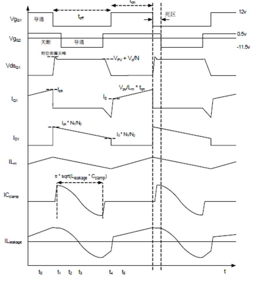
The waveform of the flyback circuit during steady-state operation is shown in Figure 7:
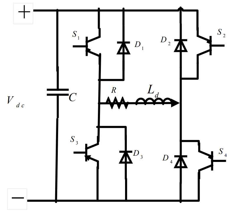
The main function of the post-stage DC-AC circuit is to invert DC power into high-quality sine-wave AC power.The structure of the single-phase full-bridge inverter circuit is shown in Figure 8:
4.3 Key technologies of single-phase solar inverters
The key technologies involved in this project mainly include the research of interleaved flyback circuits.
The flyback converter topology is chosen because it requires fewer components and does not require a freewheeling diode in the output, nor does it require an output inductor.
Figure 9 shows a simplified circuit of a single-phase active clamp flyback converter.
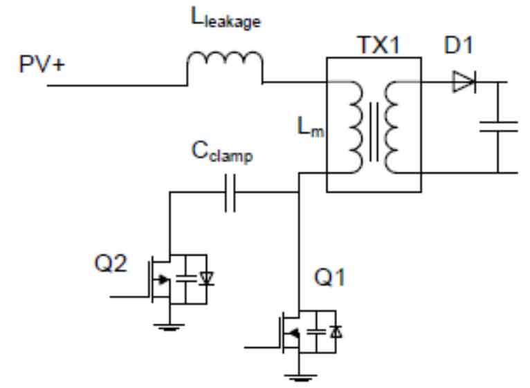
Figure 10 shows the drive circuit for a single-phase drive MOSFET.
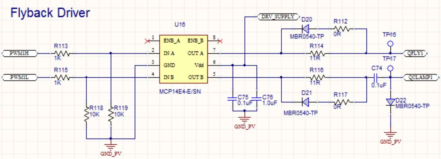
To drive a P-channel MOSFET, a negative voltage is required between the gate and source.The output of the gate drive IC (MCP14E4) is a square wave with a given duty cycle (d) and amplitude of 12V.To remove DC offset, a small ceramic capacitor is connected in series.When the duty cycle is 50% and the amplitude of the square wave is +6V to -6V, a diode is added after the capacitor, with its anode connected to the capacitor and cathode grounded.This diode clamps the positive voltage to around 0.7V and makes the amplitude entirely negative.
Figure 11 shows the gate drive waveform of two MOSFETs.
5. Summary
This article briefly introduces the theoretical basis for realizing inverting in single-phase photovoltaic grid-connected controllers, including the area equivalence principle and high-frequency modulation technology.
The system introduces the topology structure of the main circuit required for inverter implementation, especially the related topology structures of DC boost and AC inverter links.Among them, the front-stage DC-DC conversion adopts a flyback push-pull circuit (requiring bidirectional energy flow), while the rear-stage DC-AC conversion adopts a full-bridge inverter circuit (which has better inverter output waveform compared to a half-bridge inverter circuit).
Finally, we focus on two key circuits required for inverter implementation: interleaved flyback circuit and full bridge inverter circuit.We also introduce the programming techniques for the main chip (TMS320F28035) required for inverter implementation.