
The sustainable development of agriculture in arid and semi-arid regions is critically hindered by soil salinization. Subsurface pipe drainage has emerged as a pivotal engineering measure for reclaiming saline-alkali lands, offering significant advantages such as efficient land utilization, facilitation of mechanized farming, and effective regulation of the root zone soil environment. Traditional drainage systems often rely on electric-powered pumps to lift collected groundwater from sumps into open ditches, which incurs substantial operational costs and complicates management in remote agricultural areas.
The integration of photovoltaic (PV) technology presents a transformative solution. By harnessing solar energy to power drainage pumps, these systems eliminate grid dependency and reduce long-term operational expenses. However, a fundamental limitation persists: conventional solar system configurations lack energy storage (batteries), rendering the pump inoperative during nighttime. This results in a cyclical pattern where the sump water level rises overnight, submerging the drainage pipe outlets and drastically reducing or even halting the drainage flow. Consequently, the actual drainage capacity of such systems often falls short of the design requirements necessary for effective salinity control.
This article, based on extensive field monitoring and analysis, delves into the performance constraints of existing solar system setups for subsurface drainage. We present a detailed investigation into the hydraulic dynamics of the system, particularly focusing on the nocturnal water level relationship between the sump and the discharge ditch. Building upon these findings, we propose and analyze practical, cost-effective engineering modifications to significantly enhance the drainage capacity of both existing and newly constructed solar system installations.
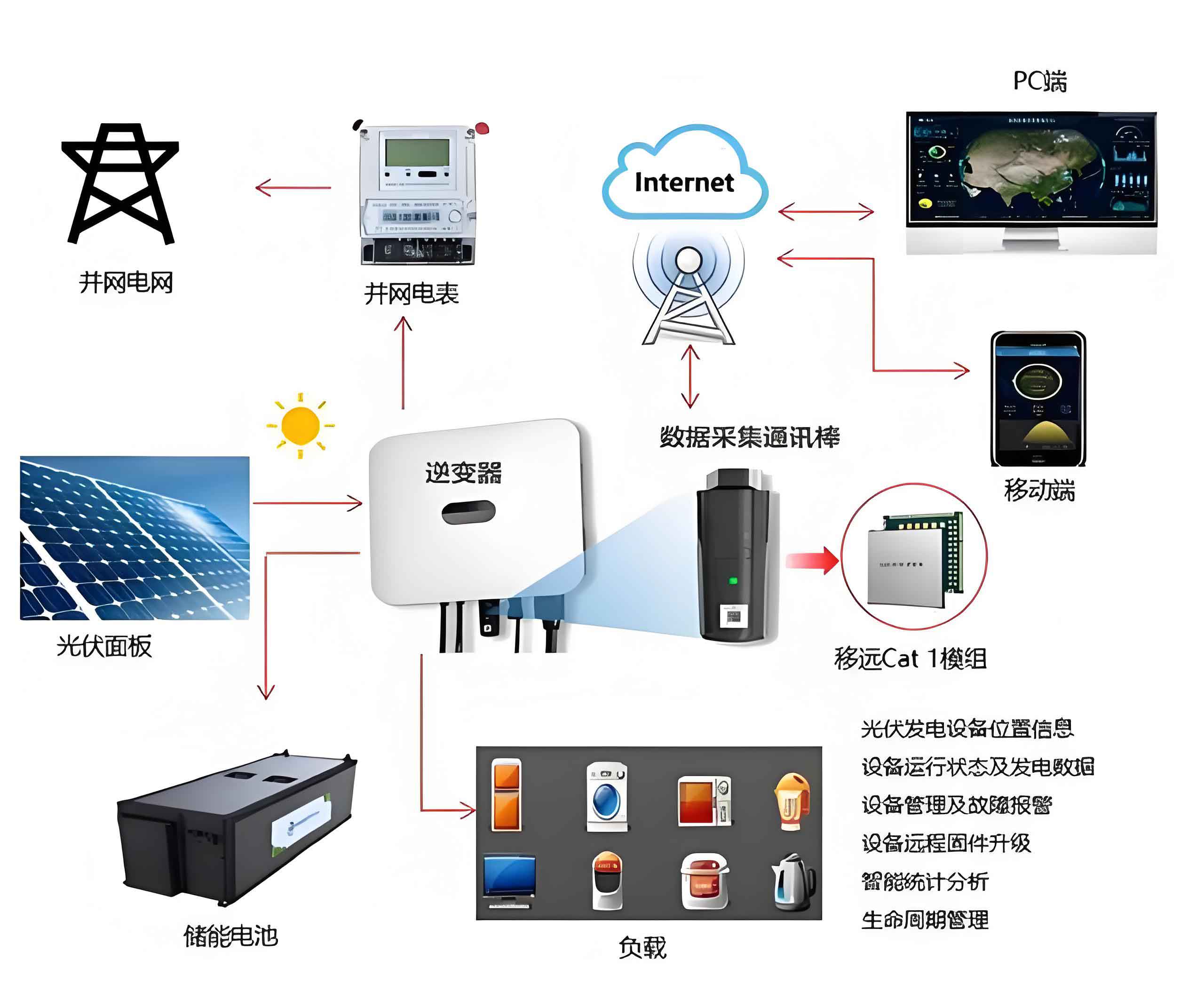
1. Performance Assessment of a Conventional Solar-Powered Drainage System
Our study was conducted in a typical solar-powered subsurface drainage area. The system comprised a two-stage network: field collector pipes (80 mm diameter, installed at 1.5-1.6 m depth with ~51 m spacing) conveying water to a main collector pipe, which subsequently discharged into a sump. A solar system powered pump, with an upgraded rated capacity of 20 m³/h, lifted water from the sump into a nearby open ditch.
Comprehensive monitoring was implemented, including flow meters at key junctions and a network of observation wells to track groundwater dynamics. The cumulative drainage discharge from the system over a representative 135-day period (excluding late-season low-flow days) was 18,270 m³, serving a commanded area of 27.4 hectares.
The average daily drainage rate, or drainage modulus, was calculated as follows:
$$ q = \frac{V}{A \times T} $$
Where \( q \) is the drainage modulus (mm/d), \( V \) is the total drainage volume (mm·m²), \( A \) is the area (m²), and \( T \) is the time (days). Substituting the values:
$$ q = \frac{18,270 \, \text{m}^3}{27.4 \times 10^4 \, \text{m}^2 \times 135 \, \text{d}} \approx 0.49 \, \text{mm/d} $$
This observed rate of 0.49 mm/d is critically low. For effective salinity control in the region, the design drainage modulus is typically set at 1.5 mm/d. The achieved performance represents only about one-third of the required capacity, confirming a severe operational limitation. The primary cause is the intermittent operation of the pump. Data reveals a distinct diurnal cycle:
| Phase | Time | Pump Status | Sump Water Level | Pipe Outlet Condition | Drainage Activity |
|---|---|---|---|---|---|
| Daytime | ~07:00 to ~18:00 | Active | Drops significantly | Free-flowing or low submergence | Active |
| Nighttime | ~18:00 to ~07:00 | Inactive | Rises to near groundwater level | Submerged under high water head | Negligible or zero |
The key nocturnal observation was that the recovered sump water level consistently established a positive hydraulic head relative to the water level in the adjacent drainage ditch. Monitoring data from the irrigation season is summarized below:
| Monitoring Date | Positive Head (Sump minus Ditch Level) (m) |
|---|---|
| May 08 | 0.38 |
| May 18 | 0.48 |
| June 02 | 0.36 |
| June 11 | 0.37 |
| July 23 | 0.35 |
This persistent positive head, averaging over 0.3 m for more than 10 hours each night, represents an untapped potential energy source that can be harnessed to improve the solar system’s overall efficiency.
2. Siphon-Assisted Drainage: Principle and Feasibility Analysis
The consistent nocturnal head difference between the sump and the ditch makes siphon-assisted drainage a highly feasible and elegant solution for upgrading existing solar system installations. A siphon operates by priming a conduit to create a continuous liquid column, allowing flow from a higher elevation source to a lower elevation outlet driven by atmospheric pressure and gravity, without requiring mechanical energy input.
The feasibility for this application rests on two conditions: 1) a sustainable positive head, which has been confirmed, and 2) a manageable vertical lift (the height from the sump water surface to the crest of the siphon pipe) to avoid cavitation. In our case, with the sump platform about 0.5 m above ground and a maximum water level recovery within 2 m of the platform, the total lift is well below the critical ~7-8 m water column limit, ensuring stable siphon operation.
The flow rate through a siphon pipe can be derived from the Bernoulli equation, considering head losses:
$$ Q = u_c \cdot A \cdot \sqrt{2g \Delta z} $$
where:
- \( Q \) = discharge (m³/s)
- \( u_c \) = flow coefficient accounting for friction and local losses
- \( A \) = cross-sectional area of the pipe (m²) = \( \pi d^2 / 4 \)
- \( g \) = acceleration due to gravity (9.81 m/s²)
- \( \Delta z \) = positive head difference between sump and ditch (m)
The flow coefficient \( u_c \) is calculated as:
$$ u_c = \frac{1}{\sqrt{1 + \lambda \frac{L}{d} + \sum \xi}} $$
Where \( \lambda \) is the Darcy-Weisbach friction factor, \( L \) is the pipe length (m), \( d \) is the pipe inner diameter (m), and \( \sum \xi \) is the sum of minor loss coefficients (inlet, bends, outlet).
3. Capacity Calculation for Siphon-Enhanced Operation
We can quantify the potential performance gain by calculating the nocturnal discharge achievable with a siphon. Using typical parameters from the study site:
| Parameter | Symbol | Value |
|---|---|---|
| Available Nocturnal Head | \( \Delta z \) | 0.3 m |
| Siphon Pipe Length | \( L \) | 14.0 m |
| Pipe Internal Diameter (Case 1) | \( d_1 \) | 0.075 m |
| Pipe Internal Diameter (Case 2) | \( d_2 \) | 0.090 m |
| Pipe Roughness (Plastic) | \( n \) | 0.011 |
| Minor Losses (Inlet, Bends, Outlet) | \( \sum \xi \) | 3.65 |
The friction factor \( \lambda \) can be estimated using the Manning-Strickler relation for full pipe flow, where the hydraulic radius \( R = d/4 \):
$$ \text{Manning: } v = \frac{1}{n} R^{2/3} S^{1/2}; \quad \text{and} \quad S = \frac{\Delta z}{L} $$
Using the Darcy-Weisbach equation \( \Delta h_f = \lambda \frac{L}{d} \frac{v^2}{2g} \) and equating head loss, \( \lambda \) can be related to \( n \) and \( d \). A simplified calculation yields the following results:
For \( d_1 = 0.075 \, \text{m} \):
Flow Coefficient \( u_{c1} \approx 0.311 \)
Velocity \( v_1 \approx 0.755 \, \text{m/s} \)
Nocturnal Discharge \( Q_1 \approx 12.0 \, \text{m}^3/\text{h} \)**
For \( d_2 = 0.090 \, \text{m} \):
Flow Coefficient \( u_{c2} \approx 0.320 \)
Velocity \( v_2 \approx 0.815 \, \text{m/s} \)
Nocturnal Discharge \( Q_2 \approx 18.6 \, \text{m}^3/\text{h} \)**
Assuming a conservative 10-hour effective nocturnal drainage period, the daily additional drainage volume would be 120 m³ (for d1) to 186 m³ (for d2). The original solar system pumped an average of about 135 m³/day during the daytime. Therefore, adding a siphon with a diameter around 0.09 m can effectively double the system’s daily output, bringing the combined (solar pump + siphon) drainage modulus much closer to the required 1.5 mm/d design target.
4. Practical Implementation Strategies for Capacity Enhancement
Based on the analysis, we propose two distinct strategies tailored for existing and new solar system projects.
4.1. Retrofit Solution for Existing Systems: Siphon Assistance
For already installed solar system drainage units, adding a siphon circuit is the most cost-effective upgrade. The implementation involves:
- Installing a siphon pipe (e.g., 90 mm HDPE) between the sump and the ditch. The inlet should be submerged near the sump base, protected by a strainer.
- The outlet must be permanently submerged below the ditch’s low-water level to maintain prime and equipped with a check valve to prevent backflow during rare reverse-head conditions.
- A priming system is required at the siphon’s crest, typically a small vacuum pump (which could be powered by a tiny, dedicated PV panel and battery) or a manual priming port.
This retrofit leverages the otherwise wasted nocturnal hydraulic head, requiring minimal additional infrastructure and operational cost.
4.2. Integrated Design for New Systems: Gravity Overflow Pipe
For new solar system installations, a more integrated and passive solution is recommended during the design phase:
- Incorporate a horizontal gravity flow pipe (connector) directly from the sump wall to the ditch, installed at a carefully calculated elevation.
- The inlet inside the sump is set at an elevation slightly above the intended operational low-water level for the pump but below the level where subsurface pipe efficiency drops due to submergence (e.g., 2.0-2.5 m below the sump rim).
- The pipe maintains a constant downward slope to the ditch. A check valve at the ditch outlet is essential.
This design creates a hybrid solar system: during the day, the PV pump actively lowers the water level below the gravity pipe inlet; at night, when the pump stops and water rises, once it exceeds the inlet elevation, continuous gravity drainage initiates automatically. This method is completely passive, requires no priming, and is highly reliable.
| Feature | Conventional Solar-Only System | Retrofit with Siphon | New System with Gravity Pipe |
|---|---|---|---|
| Nocturnal Drainage | None | Active (Siphon Flow) | Active (Gravity Flow) |
| Energy Use at Night | None | Minimal (for priming) | None |
| Drainage Modulus Gain | Baseline (~0.5 mm/d) | Can double (~1.0 mm/d) | Can double or more (~1.0-1.5 mm/d) |
| Implementation Complexity | N/A | Moderate (retrofit) | Low (integrated in design) |
| Operational Maintenance | Pump maintenance only | Adds siphon/priming check | Adds check valve maintenance |
| Relative Cost | Baseline | Low (adds pipe & primer) | Very Low (adds pipe during build) |
5. Conclusion
The widespread application of photovoltaic technology in agricultural drainage marks a significant step towards sustainable land and water management. However, the inherent limitation of diurnal operation in battery-less solar system configurations severely caps their effectiveness for subsurface drainage, a process that ideally requires 24-hour operation.
Our field investigation conclusively demonstrates that the existing solar system setups operate at only a fraction of their intended capacity, primarily due to the loss of drainage head and function during the night. The critical discovery of a consistent and usable nocturnal hydraulic head difference between the sump and the discharge ditch opens the door for simple, physics-based enhancements.
For the vast number of already deployed solar system drainage units, the integration of a siphon-assisted drainage circuit presents a highly viable and economical retrofit strategy. As calculated, a properly sized siphon can provide nocturnal discharge comparable to the daytime solar pump output, effectively doubling the system’s daily drainage volume and significantly improving its salinity control performance.
For future projects, the design should inherently include a gravity overflow pipe. This integrated approach creates a robust hybrid solar system that combines active solar-powered pumping with passive nighttime gravity drainage, ensuring continuous operation and maximizing the return on investment. By adopting these engineered improvements, the full potential of solar system technology can be realized, providing a reliable, cost-effective, and sustainable solution for reclaiming saline-alkali lands and securing agricultural productivity in arid regions worldwide.