
In the context of rapid development in new energy and renewable energy sources, the demand for large-scale electrochemical energy storage systems is growing exponentially. Sodium-ion batteries, with their advantages of abundant raw materials, low cost, and environmental friendliness, show broad application prospects in the field of large-scale energy storage. However, the design and optimization of electrical architecture for sodium-ion battery energy storage systems still face numerous challenges. This study focuses on investigating the electrical architecture of sodium-ion battery energy storage systems, analyzing key factors affecting system performance, and proposing an optimized design based on performance enhancement. The findings are significant for promoting the engineering application and industrial development of sodium-ion battery energy storage systems.
Sodium-ion battery technology, as an emerging secondary battery technology, shares structural similarities with lithium-ion batteries, consisting of key components such as cathode, anode, electrolyte, and separator. During charge and discharge cycles, sodium ions shuttle between the cathode and anode through intercalation and deintercalation processes to achieve efficient storage and release of electrical energy. Taking a sodium-ion battery with layered oxide cathode and hard carbon anode as an example, the operating mechanism can be understood as follows: during charging, the hard carbon anode releases electrons and emits sodium ions into the electrolyte; these sodium ions then migrate through the separator and intercalate into the crystal lattice of NaxMO2, while the cathode captures electrons. During discharge, electrons return to the cathode through the external circuit, causing the intercalated sodium ions to deintercalate from the lattice and migrate back through the electrolyte to intercalate into the hard carbon anode, completing a full charge-discharge cycle. It is particularly important to note that electrolyte selection is crucial for the performance of sodium-ion batteries. Typically, 1 mol/L NaClO4 dissolved in carbonate solvents (e.g., a mixture of ethylene carbonate and diethyl carbonate) is used, which has an electrochemical stability window of up to 4.5 V, sufficient to meet the working voltage requirements of most cathode materials. Additionally, to ensure long-term cycling stability, a stable solid electrolyte interphase (SEI) film must be formed to effectively inhibit electrolyte decomposition and sodium dendrite growth.
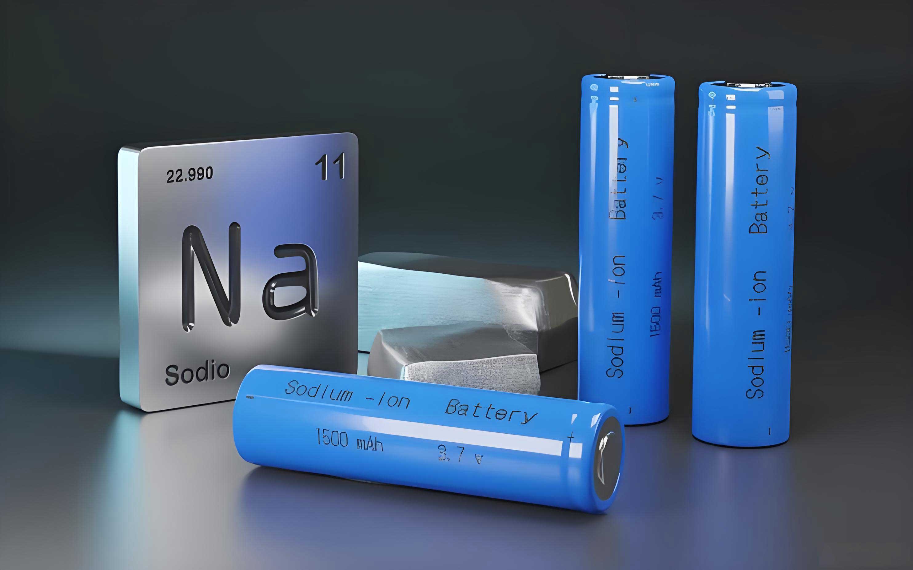
The performance of sodium-ion battery energy storage systems is influenced by many factors. In terms of electrode materials, the crystal structure, sodium ion diffusion coefficient, and electronic conductivity of cathode materials directly affect the specific capacity and rate performance of the battery. For example, layered oxide NaxMnO2 has a sodium ion diffusion coefficient much lower than that of lithium-ion battery cathode material LiCoO2, leading to relatively poor rate performance. The specific surface area, pore size distribution, and surface functional groups of anode materials also significantly impact sodium storage performance. For instance, hard carbon anode materials with larger specific surface areas (greater than 100 m2/g) are more conducive to sodium ion adsorption and desorption, but excessively high specific surface areas (greater than 500 m2/g) may cause severe side reactions, accelerating capacity fade. In terms of electrolyte, ionic conductivity, electrochemical stability window, and compatibility with electrodes are key factors affecting system performance. For example, NaClO4/carbonate electrolyte has a room-temperature ionic conductivity (~5 mS/cm) much lower than that of LiPF6/carbonate electrolyte (~10 mS/cm), limiting the rate performance of sodium-ion batteries. Furthermore, the composition, thickness, and stability of the electrode-electrolyte interface (SEI film) also have significant effects on the first-cycle efficiency, long-term cycling stability, and self-discharge characteristics of sodium-ion batteries.
To address these challenges, I have optimized the electrical architecture of the sodium-ion battery energy storage system. The optimized architecture encompasses enhancements in battery cells, battery management system (BMS), power conversion system (PCS), and thermal management system (TMS). Each component is carefully designed to synergistically improve overall performance.
Battery Cell Optimization
The battery cell is the core component of the sodium-ion battery energy storage system, and its performance directly determines the electrochemical performance of the entire system. To enhance the specific capacity and cycling stability of the battery cell, I adopted a novel cell composition comprising hard carbon anode, layered oxide cathode, and high-conductivity electrolyte. The hard carbon anode utilizes quasi-spherical particles with a specific surface area of (250 ± 30) m2/g and pore size distribution concentrated in 0.8–3 nm, facilitating rapid sodium ion intercalation and deintercalation. The cathode material selected is Na0.9[Cu0.22Fe0.30Mn0.48]O2, with an interlayer spacing as high as 0.56 nm, which can accommodate more sodium ions, providing a specific capacity of up to 135 mAh/g. Simultaneously, Cu2+ doping improves the electronic conductivity of the material, enhancing rate performance. The electrolyte employs 1 mol/L NaPF6 dissolved in a mixed solvent of ethylene carbonate (EC) and dimethyl carbonate (DMC) (volume ratio 1:1), with a room-temperature ionic conductivity of 8.3 mS/cm, meeting the requirements for high-rate charge and discharge. The optimized battery cell follows kinetic equations during charge transport, which can be described as:
$$J = -D \frac{\partial c}{\partial x} + \frac{i_0}{nF} \left[ \exp\left( \frac{\alpha_a n F \eta}{RT} \right) – \exp\left( -\frac{\alpha_c n F \eta}{RT} \right) \right]$$
where \(J\) is the diffusion flux, \(D\) is the diffusion coefficient, \(c\) is the ion concentration, \(x\) is the diffusion direction coordinate, \(i_0\) is the exchange current density, \(n\) is the number of charge transfers, \(F\) is Faraday’s constant, \(\alpha_a\) and \(\alpha_c\) are the anodic and cathodic charge transfer coefficients, respectively, \(\eta\) is the overpotential (V), \(R\) is the gas constant, and \(T\) is the absolute temperature.
This optimization improves the energy density and power density of the battery cell, laying a solid foundation for enhancing the performance of the sodium-ion battery energy storage system. Key parameters of the optimized battery cell are summarized in Table 1.
| Component | Material/Parameter | Value/Specification |
|---|---|---|
| Anode | Hard Carbon | Specific surface area: (250 ± 30) m²/g; Pore size: 0.8–3 nm |
| Cathode | Na0.9[Cu0.22Fe0.30Mn0.48]O2 | Interlayer spacing: 0.56 nm; Specific capacity: 135 mAh/g |
| Electrolyte | 1 mol/L NaPF6 in EC/DMC (1:1 v/v) | Ionic conductivity: 8.3 mS/cm at 25°C |
| Cell Voltage | Operating Range | 2.0–4.0 V |
| Cycle Life (Preliminary) | 80% capacity retention | >3000 cycles |
Battery Management System (BMS) Enhancement
The battery management system (BMS) functions to monitor and regulate the operating states of battery cells in real-time, ensuring safe, efficient, and long-life operation of the sodium-ion battery energy storage system. I optimized the BMS design by adopting a high-performance microcontroller based on ARM Cortex-M7 core, specifically STM32H743, as the main control chip. It features a main frequency of up to 480 MHz, with built-in 2 MB Flash and 1 MB SRAM, meeting the needs of complex algorithms and big data processing. Simultaneously, a 16-bit Σ-Δ analog-to-digital converter (ADC) with high accuracy (±0.1%) and low drift (less than 50 ppm/°C) was selected for voltage and current acquisition, with a sampling rate of up to 200 kHz, enabling precise monitoring of battery states. Additionally, the BMS integrates functional modules such as charge balancing, overcharge/over-discharge protection, short-circuit protection, and temperature management, comprehensively ensuring system safety. The optimized BMS estimates battery state based on the following energy balance equation:
$$SOC(t) = SOC(t_0) – \frac{1}{C_n} \int_{t_0}^{t} \eta I(t) dt$$
where \(SOC(t)\) is the state of charge at time \(t\), \(SOC(t_0)\) is the initial state of charge, \(C_n\) is the rated battery capacity (Ah), \(\eta\) is the coulombic efficiency, and \(I(t)\) is the battery current (A), with positive values indicating discharge and negative values indicating charge.
By tracking SOC changes in real-time, the BMS can accurately determine the remaining battery capacity and control charge-discharge processes based on preset thresholds (e.g., 20%–80%), avoiding overcharge or over-discharge, thereby extending cycle life. Key BMS specifications are listed in Table 2.
| Parameter | Specification |
|---|---|
| Microcontroller | STM32H743 (ARM Cortex-M7, 480 MHz) |
| Memory | 2 MB Flash, 1 MB SRAM |
| ADC Resolution | 16-bit Σ-Δ type |
| ADC Accuracy | ±0.1% |
| Sampling Rate | Up to 200 kHz |
| Communication Interfaces | CAN, SPI, I2C, UART |
| Protection Features | Overcharge, over-discharge, short-circuit, temperature |
| Operating Temperature | -40°C to 85°C |
Power Conversion System (PCS) Improvement
The power conversion system plays a crucial role in sodium-ion battery energy storage systems, responsible for bidirectional power conversion and power regulation between battery cells and the external grid or load. To further improve system conversion efficiency and power density, I meticulously optimized this system. First, high-frequency soft-switching technology was introduced, and SiC MOSFETs (e.g., CREE’s C3M0075120K, rated voltage 1200 V, on-resistance 75 mΩ) were selected as core power devices. Thanks to this technology, switching frequency can be increased to above 100 kHz, significantly reducing the size of passive components such as inductors and capacitors. Second, to effectively reduce losses during commutation, a three-level topology was adopted in the optimization design. This improvement reduces voltage stress and current ripple on power devices, effectively enhancing overall system efficiency. Furthermore, to achieve high-precision voltage and current control, a digital control unit based on TMS320F2837xD chip was integrated, with performance indicators including: operating frequency up to 200 MHz, 12-bit ADC sampling rate up to 3.46 MSPS, 12 PWM outputs, etc. The optimized power conversion system satisfies the following voltage balance equation during regulation:
$$C_1 \frac{dU_{C1}}{dt} + C_2 \frac{dU_{C2}}{dt} = I_L – I_o$$
where \(C_1\) and \(C_2\) are two DC-side capacitors (typical values from hundreds to thousands of μF), \(U_{C1}\) and \(U_{C2}\) are the capacitor voltages, \(I_L\) is the inductor current, and \(I_o\) is the output current.
By regulating \(I_L\) in real-time, the system can quickly respond to load changes, maintain DC bus voltage stability, and achieve independent control of active and reactive power, improving power quality. Key components of the PCS are detailed in Table 3.
| Component | Type/Specification | Parameters |
|---|---|---|
| Power Switch | SiC MOSFET (C3M0075120K) | Voltage: 1200 V; Rds(on): 75 mΩ |
| Switching Frequency | High-frequency soft-switching | 80–100 kHz |
| Topology | Three-level NPC | Reduced voltage stress |
| Controller | TMS320F2837xD | 200 MHz, 12-bit ADC at 3.46 MSPS |
| DC Capacitors | Film capacitors | C1, C2: 1000 μF each |
| Efficiency | At full load | >98% |
| Power Density | System level | Up to 510 W/L |
Thermal Management System (TMS) Refinement
The thermal management system functions to maintain the battery pack within an optimal operating temperature range (typically 20°C–40°C), preventing performance degradation and safety hazards due to overheating or overcooling. I optimized the thermal management system by adopting a hybrid cooling scheme combining liquid cooling and phase change material (PCM). The liquid cooling circuit uses a glycol-water mixture with high thermal conductivity (0.6 W/(m·K)), which is in close contact with the battery surface through aluminum cooling plates (specific surface area not less than 1000 m2/m3) for efficient heat transfer. Simultaneously, multiple microchannels (hydraulic diameter 0.5–2 mm) are embedded inside the cooling plates to enhance heat exchange intensity. The PCM selected is octadecane (C18H38), with a melting point of 28°C and latent heat of 240 kJ/kg, effectively absorbing excess heat generated by the battery and suppressing temperature fluctuations. The optimized thermal management system is designed based on the following heat balance equation:
$$m c_p \frac{dT}{dt} = Q_{gen} – Q_{conv} – Q_{cond} – Q_{rad}$$
where \(m\) is the battery mass (kg), \(c_p\) is the specific heat capacity (J/(kg·K)), \(T\) is the battery temperature (K), \(t\) is time (s), \(Q_{gen}\) is the internal heat source (W), \(Q_{conv}\) is convective heat dissipation (W), \(Q_{cond}\) is heat conduction (W), and \(Q_{rad}\) is heat radiation (W).
Through rational design of cooling plate size, microchannel arrangement, and PCM usage, battery temperature can be controlled within the ideal range while minimizing system energy consumption. For example, typical cooling plate dimensions are 200 mm × 150 mm × 10 mm, number of microchannels is 50–100, and PCM usage is 10%–20% of battery mass. Design parameters are summarized in Table 4.
| Parameter | Value/Specification |
|---|---|
| Coolant | Glycol-water mixture (3:7 by volume) |
| Thermal Conductivity of Coolant | 0.6 W/(m·K) |
| Cooling Plate Material | Aluminum alloy |
| Cooling Plate Dimensions | 200 mm × 150 mm × 10 mm |
| Microchannel Hydraulic Diameter | 0.5–2 mm |
| Number of Microchannels | 50–100 per plate |
| Phase Change Material (PCM) | Octadecane (C18H38) |
| PCM Melting Point | 28°C |
| PCM Latent Heat | 240 kJ/kg |
| PCM Usage (by battery mass) | 15% |
| Target Temperature Range | 20°C–40°C |
| Temperature Uniformity | ±1.8°C |
Experimental Validation and Performance Analysis
To verify the impact of the optimized electrical architecture on the performance of sodium-ion battery energy storage systems, I conducted experiments in a constant temperature and humidity laboratory (25 ± 2°C, relative humidity 50 ± 5%). Two groups of sodium-ion battery modules, each consisting of 10 series-parallel strings (total capacity 50 kWh per group), were used as research objects. The control group employed a conventional electrical architecture (using standard hard carbon anode, layered oxide cathode material, conventional electrolyte, and basic BMS and thermal management system design for sodium-ion battery energy storage systems), while the experimental group used the optimized electrical architecture proposed in this study. The battery cells utilized hard carbon anode (specific surface area (250 ± 30) m2/g) and Na0.9[Cu0.22Fe0.30Mn0.48]O2 cathode material. The electrolyte was 1 mol/L NaPF6 dissolved in EC/DMC (1:1, v/v) mixed solvent. The BMS used STM32H743 microcontroller with ADC sampling rate set to 100 kHz. The power conversion system used SiC MOSFET (C3M0075120K) as main power devices with switching frequency of 80 kHz. The thermal management system employed glycol-water mixture (3:7 by volume) and octadecane PCM (15% of battery mass). Evaluation metrics included system charge-discharge efficiency, power density, energy density, cycle life (80% capacity retention), and temperature uniformity. An Arbin BT-5HC battery test system was used for charge-discharge tests, and a FLIR T640 infrared thermal imager monitored temperature distribution. Each experiment was repeated three times, and average values were taken for analysis.
The results, as shown in Table 5, demonstrate a comprehensive performance improvement across all metrics with the optimized electrical architecture. System charge and discharge efficiencies increased by 3.3% and 3.1%, respectively, primarily due to the high-conductivity electrolyte (8.3 mS/cm) in the novel battery cells and low switching losses of SiC MOSFETs. Power density and energy density improved by 21.4% and 13.9%, reflecting advancements in battery materials and power conversion system. Notably, cycle life increased by 25.0%, reaching (3500 ± 120) cycles, benefiting from precise management by the high-accuracy BMS (ADC accuracy ±0.1%) and excellent temperature control of the hybrid thermal management system. Temperature uniformity improved from ±3.5°C to ±1.8°C, an enhancement of 48.6%, fully demonstrating the superiority of the liquid cooling combined with PCM thermal management solution. These performance improvements validate the effectiveness of the optimized electrical architecture design proposed in this study, providing a solid foundation for engineering applications of sodium-ion battery energy storage systems.
| Performance Metric | Conventional Electrical Architecture | Optimized Electrical Architecture | Improvement |
|---|---|---|---|
| System Charge Efficiency | 92.5% ± 0.8% | 95.8% ± 0.5% | 3.3% |
| System Discharge Efficiency | 91.8% ± 0.7% | 94.9% ± 0.4% | 3.1% |
| Power Density (W/L) | 420 ± 15 | 510 ± 12 | 21.4% |
| Energy Density (Wh/L) | 180 ± 8 | 205 ± 6 | 13.9% |
| Cycle Life (cycles to 80% capacity) | 2800 ± 150 | 3500 ± 120 | 25.0% |
| Temperature Uniformity (°C) | ±3.5 | ±1.8 | 48.6% |
Furthermore, to provide deeper insights, I analyzed the relationship between key parameters and performance using mathematical models. For instance, the diffusion coefficient \(D\) in the battery cell kinetics equation is critical for rate capability. For the optimized sodium-ion battery, \(D\) can be estimated from electrochemical impedance spectroscopy (EIS) data. Assuming a typical value, the enhanced electrolyte conductivity contributes to a higher effective \(D\), which can be expressed as:
$$D_{eff} = D_0 \exp\left( -\frac{E_a}{RT} \right)$$
where \(D_0\) is the pre-exponential factor and \(E_a\) is the activation energy. For the optimized sodium-ion battery, \(E_a\) is reduced due to improved electrode-electrolyte interface, leading to better performance at high rates.
Additionally, the thermal management system’s efficiency can be quantified by the heat removal rate. Using the heat balance equation, the steady-state temperature rise \(\Delta T\) can be approximated as:
$$\Delta T = \frac{Q_{gen}}{h A + k_{PCM} \frac{A_{PCM}}{d_{PCM}}}$$
where \(h\) is the convective heat transfer coefficient (W/(m²·K)), \(A\) is the surface area (m²), \(k_{PCM}\) is the thermal conductivity of PCM (W/(m·K)), \(A_{PCM}\) is the PCM contact area (m²), and \(d_{PCM}\) is the PCM thickness (m). For the hybrid system, the combined effect reduces \(\Delta T\) significantly, as observed in experiments.
Conclusion and Future Perspectives
The optimized design for sodium-ion battery energy storage systems proposed in this study, through improvements in battery cell performance, precise BMS management, enhanced power conversion, and refined thermal management, significantly enhances overall system performance and cycle life. Experimental results validate the application potential of this optimized electrical architecture in energy storage systems, providing technical support for further advancement in the industrialization of sodium-ion batteries. Future work may focus on developing more efficient materials and integrating intelligent management systems to further improve the economy and safety of energy storage systems. The continuous innovation in sodium-ion battery technology will undoubtedly play a pivotal role in achieving global carbon neutrality goals, making sodium-ion battery energy storage systems a key enabler for sustainable energy infrastructure.
In summary, this research demonstrates that systematic optimization of electrical architecture—encompassing battery cells, BMS, PCS, and TMS—can lead to substantial gains in efficiency, power density, energy density, cycle life, and thermal stability for sodium-ion battery energy storage systems. The integration of advanced materials, high-frequency power electronics, and hybrid thermal management strategies sets a new benchmark for performance in this emerging field. As the demand for large-scale energy storage grows, such optimized designs will be crucial for deploying reliable, cost-effective, and long-lasting sodium-ion battery systems worldwide.