
Under the guidance of reducing the use of fossil fuels and achieving the “dual carbon” goal, the development momentum of renewable energy generation is very rapid, but the inherent instability is the biggest obstacle to achieving large-scale grid connection of renewable electricity. Energy storage technology is one of the best ways to solve the above problems.
Compressed air energy storage (CAES), as an energy storage technology with broad development prospects, has the advantages of low construction cost, high energy storage efficiency, and large energy storage capacity. Among them, advanced adiabatic compressed air energy storage (AA-CAES) has the advantage of achieving zero emissions
Shi has attracted a large amount of research from domestic and foreign scholars. Design the layout of the heat storage system in the AA CAES system; Analyze and explore the performance changes of the system under the conditions of changing the design structure; Analyzed and compared the cycle efficiency of several AA-CAES systems with different configurations; Studied the impact of the thermodynamic characteristics of the gas storage chamber on the performance of the energy storage system; Propose a comprehensive system that combines fans with the AA CAES system. We have studied a scheme for achieving cogeneration using an advanced adiabatic compressed air energy storage system. By adding an auxiliary power supply, the heat from the heat storage system is recovered and supplied externally. By establishing a micro energy comprehensive system and utilizing equipment such as waste heat recovery boilers, advanced adiabatic compressed air energy storage systems have been achieved for combined cooling, heating, and power supply. By introducing air from the heat exchanger into the evaporator for recovery, the waste heat recovery of the compressed air energy storage system is achieved. Analyzing the impact of thermal energy utilization rate on the overall efficiency of compressed air energy storage systems, it was found that reasonable allocation of thermal energy can improve system efficiency.
This article analyzes the sources of waste heat in the AA-CAES system, and takes a 100 MW system as the object to study optimization methods for reducing and fully utilizing this part of waste heat.
1.Waste heat analysis of AA-CAES system
The principle system of advanced adiabatic compressed air energy storage is shown in Figure 1.
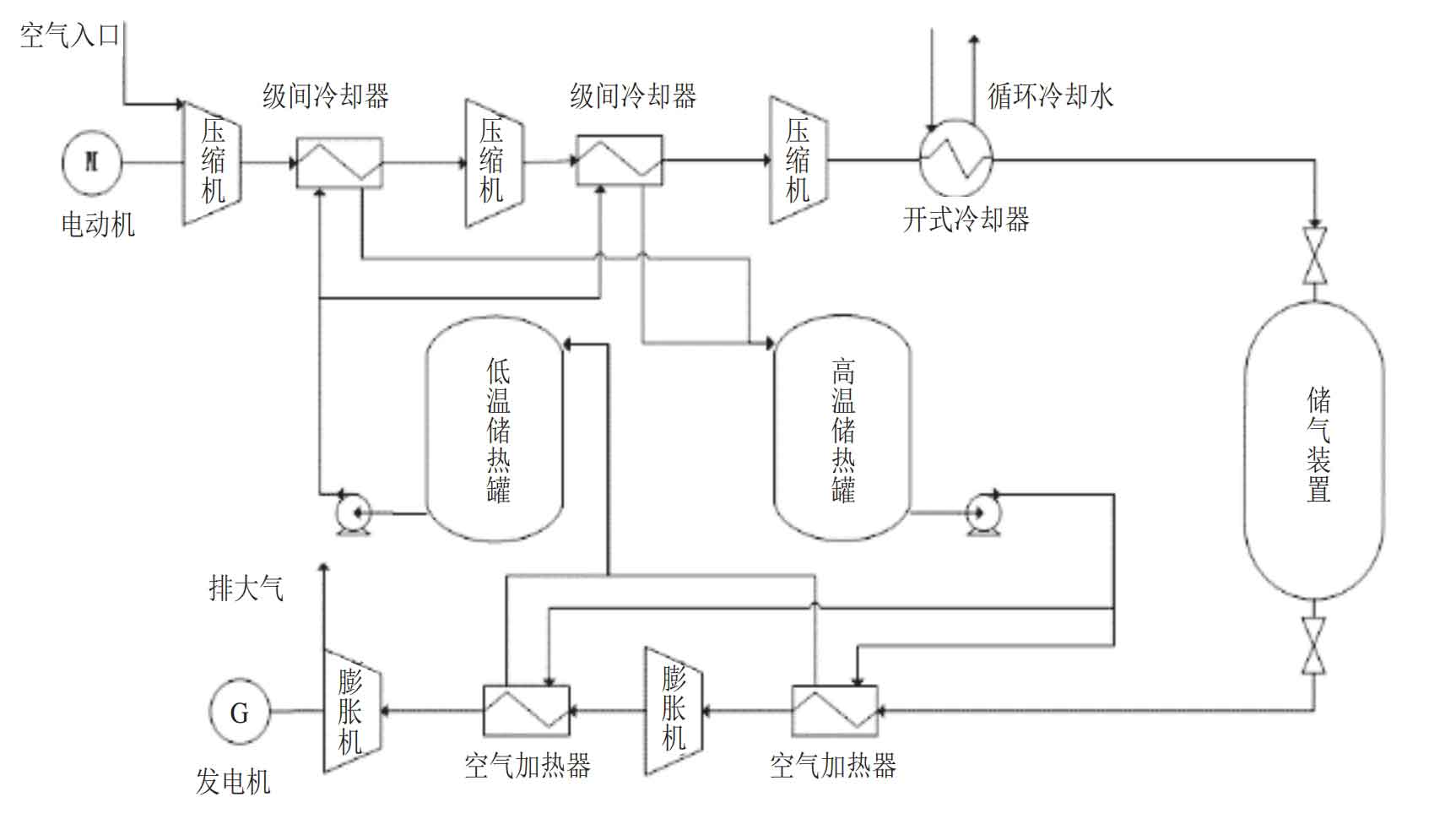
When storing energy in the system, the air is compressed and pressurized by multi-stage compressors before entering the gas storage device for storage. At the same time, interstage cooling is carried out during the compression process, and the heat is stored in the high-temperature heat storage tank from the low-temperature heat storage medium, completing the energy storage process; When the system releases energy, the high-pressure cold air in the gas storage device is heated by a high-temperature heat storage medium, which then drives the expander to do power and generate electricity.
The waste heat in the AA-CAES system mainly consists of three parts. During the compression process, the temperature of air after adiabatic compression by the compressor will significantly increase, which is caused by the combination of gas adiabatic compression heating and energy conversion entropy increasing heat release. Most of the heat in high-temperature air is stored in a high-temperature heat tank after being exchanged by a heat exchanger for energy release. Some of the excess heat is naturally dissipated by the heat exchanger and pipelines, while the remaining low-grade and difficult to use heat is carried away by circulating cooling water and dissipated into the environment. During the expansion process, in order to ensure smooth exhaust, the final exhaust pressure needs to be slightly higher than atmospheric pressure. Under this condition, the exhaust temperature is generally higher than the ambient temperature, and the utilization of this heat is relatively limited. Only by optimizing system parameters can the exhaust temperature be reduced as much as possible to reduce the heat loss in this part of the exhaust.
After the completion of a charging and discharging process, there will be some unused high-temperature thermal storage media retained in the system. In the compression and expansion process of an ideal gas, the absorption and release of heat are equal, but in reality, there is also an entropy increase in the electric heat conversion during the air compression process. At the same time, the heat exchanger has limitations on the heat transfer end difference. Therefore, after the expansion power generation part emits all the electricity, there will still be some heat that is not utilized and stored in a high-temperature heat storage tank in the form of high-temperature heat storage media (high-temperature hot water, molten salt, or thermal oil, etc.). The heat in the unused high-temperature heat storage medium in this part of the system is the main source of waste heat that can be utilized in compressed air energy storage power plants. This part of the heat has relatively high quality and stable source (always present after each charge and discharge). Usually, this part of the high-temperature heat storage medium is cooled with circulating cooling water and returned to the low-temperature hot tank for storage, which is used for interstage cooling in the next air compression process. This method not only fails to recover heat, but also requires a large amount of electrical energy and cooling water, resulting in significant waste and reducing system efficiency.
The research in this article mainly focuses on this part of heat, which will be utilized by increasing the inlet temperature of the expander and adding an organic Rankine cycle power generation system, in order to improve the efficiency of the system.
2.Unit Overview and Modeling
This article takes a 100 MW level compressed air energy storage system as the research object. The energy storage system stores and releases energy once a day, with a storage time of 8 hours and a release time of 5 hours. The system is set to four stages of compression and three stages of expansion, using high-pressure hot water as the intermediate heat storage medium. The water temperature varies from 50 to 190 ℃, and the rated gas storage pressure of the gas storage device is 12 MPa. The gas storage temperature is 40 ℃. In the compression system, the outlet air of the fourth stage compressor is cooled and stored in the gas storage device, without heat recovery. The design parameters of the inlet and outlet air and heat storage system of the other stages of compressors are listed in Table 1.
| Parameter | First stage compressor | Secondary compressor | Three stage compressor | Four stage compressor |
| Intake pressure/bar (a) | 0.39 | 4.8 | 18.2 | 67.5 |
| Intake temperature/℃ | 6.7 | 40 | 40 | 40 |
| Exhaust pressure/bar (a) | 5.1 | 18.5 | 67.8 | 124 |
| Exhaust temperature/℃ | 205 | 205 | 205 | 108 |
| Intake flow rate/(t/h) | 532 | 532 | 532 | 532 |
| Air water cooler inlet temperature/℃ | 50 | 50 | 50 | — |
| Air water cooler outlet temperature/℃ | 190 | 190 | 190 | — |
| Water side flow rate of gas-water cooler/(t/h) | 120 | 120 | 125 | — |
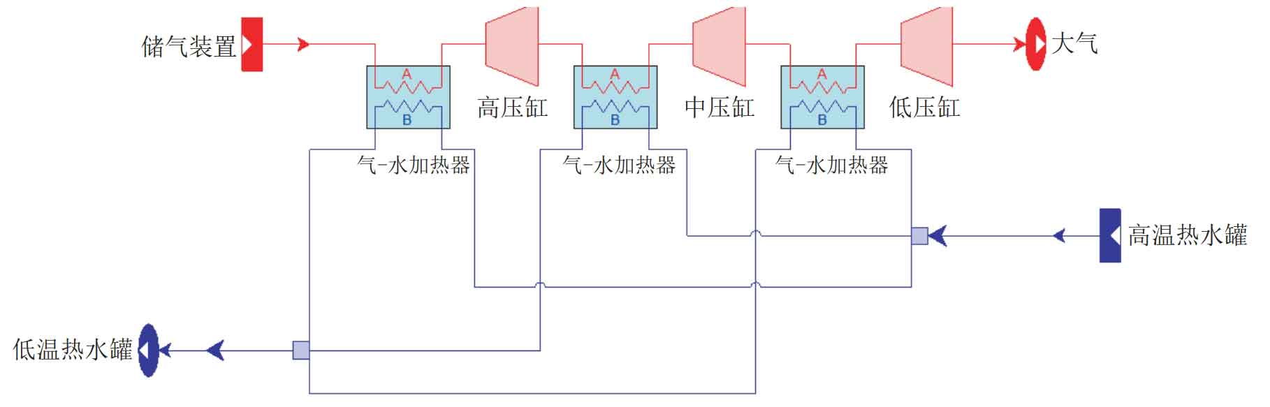
According to the calculations in Table 1 and Table 2, it can be concluded that after the end of a single discharge, there are still 170 tons of high-temperature hot water in the system’s high-temperature hot water tank that have not undergone heat exchange, which is the residual heat that can be utilized by the energy storage system. Considering that the waste heat utilization in this article is achieved during the expansion power generation process, only modeling and analysis of the expansion power generation system are needed. The modeling software is Thermoflex software, and the expansion power generation system model built is shown in Figure 2.
| Project | High pressure cylinder | Intermediate pressure cylinder | Low pressure cylinder |
| Intake pressure/bar (a) | 110 | 25.6 | 6.1 |
| Intake temperature/℃ | 175 | 175 | 175 |
| Exhaust pressure/bar (a) | 26 | 6.4 | 1.03 |
| Exhaust temperature/℃ | 40 | 40 | 10 |
| Intake flow rate/(t/h) | 848 | 848 | 848 |
| Air water heater inlet water temperature/℃ | 190 | 190 | 190 |
| Outlet water temperature of gas-water heater/℃ | 50 | 50 | 50 |
| Water side flow rate of gas-water heater/(t/h) | 193 | 181 | 176 |
The comparison between model calculation data and design parameters is shown in Table 3.
| Project | Design value of high-pressure cylinder | High pressure cylinder simulation value | High pressure cylinder error/% | Design value of intermediate pressure cylinder | Analog value of intermediate pressure cylinder | Error of intermediate pressure cylinder/% | Design value of low-pressure cylinder | Low pressure cylinder simulation value | Low pressure cylinder error/% |
| Intake pressure/bar (a) | 110 | 110 | 0 | 25.6 | 25.6 | 0 | 6.1 | 6.1 | 0 |
| Intake temperature/℃ | 175 | 175 | 0 | 175 | 175 | 0 | 175 | 175 | 0 |
| Exhaust pressure/bar (a) | 26 | 25.86 | -0.54 | 6.4 | 6.16 | -0.38 | 1.03 | 1.03 | 0 |
| Exhaust temperature/℃ | 40 | 39.72 | -0.70 | 40 | 40.3 | 0.3 | 10 | 10.5 | 0.5 |
| Intake flow rate/(t/h) | 848 | 848 | 0 | 848 | 848 | 0 | 848 | 848 | 0 |
| Air water heater inlet water temperature/℃ | 190 | 190 | 0 | 190 | 190 | 0 | 190 | 190 | 0 |
| Outlet water temperature of gas-water heater/℃ | 50 | 50 | 0 | 50 | 50 | 0 | 50 | 50 | 0 |
| Water side flow rate of gas-water heater/(t/h) | 193 | 193.86 | 3.04 | 190.16 | 5.08 | 176 | 176 | 187.14 | 6.33 |
It can be seen that the largest error in the table is the water side flow rate of the air water heater before the inlet of the low-pressure cylinder, which is 6.33%, while the other errors are all below 5.1%. Therefore, it can be considered that the built simulation model has a high degree of consistency with the actual system, meets the accuracy requirements of practical engineering, and can be used for the next step of optimization research.
3.Optimization and Result Analysis
3.1 Inlet temperature of expander
In the original system design parameters, the inlet temperature of each stage of the expander was 175 ℃. Based on the unchanged structure of the original system, the impact of increasing inlet temperature on power generation was first studied. Considering the actual situation of the heat exchanger end difference, the system conditions were simulated at inlet temperatures of 180 ℃ and 185 ℃, respectively. The simulation results are listed in Table 4.
| Project | Inlet temperature 180 ℃ High pressure cylinder | Inlet temperature 180 ℃, intermediate pressure cylinder | Inlet temperature 180 ℃ Low pressure cylinder | Inlet temperature 185 ℃ High pressure cylinder | Inlet temperature 185 ℃ High pressure cylinder | Inlet temperature 185 ℃ Low pressure cylinder |
| Intake pressure/bar (a) | 110 | 25.75 | 6.134 | 110 | 25.89 | 6.167 |
| Intake temperature/℃ | 180 | 180 | 180 | 185 | 185 | 185 |
| Exhaust pressure/bar (a) | 26.01 | 6.20 | 1.03 | 26.15 | 6.23 | 1.03 |
| Exhaust temperature/℃ | 43.38 | 43.84 | 13.31 | 47.04 | 47.38 | 16.12 |
| Intake flow rate/(t/h) | 848 | 848 | 848 | 848 | 848 | 848 |
| Air water heater inlet water temperature/℃ | 190 | 190 | 190 | 190 | 190 | 190 |
| Outlet water temperature of gas-water heater/℃ | 55.33 | 58.34 | 58.13 | 65.11 | 70.74 | 70.20 |
| Water side flow rate of gas-water heater/(t/h) | 214.10 | 204.01 | 200.67 | 238.48 | 226.95 | 222.86 |
According to the simulation results, as the intake temperature increases, the power generation also increases. For every 5 ℃ increase in intake temperature, the power generation increases by approximately 1.25%. At the same time, it can also be observed that as the inlet temperature increases, the outlet water temperature of the gas-water heater also increases, and the water side flow rate of the heater rapidly increases, and the original heat storage system cannot provide sufficient water side flow rate. Taking the intake temperature of 180 ℃ as an example, the required flow rate on the water side of the heater is 618.78 t/h, an increase of 42.59 t/h compared to the design condition (simulated value), and a gap of 8.59 t/h. Based on the water temperature variation range of 50-190 ℃ and a specific heat capacity of 4.2 kJ/(kg · ℃), the equivalent thermal power is about 1403 kW, which is higher than the power generation increment of 1253 kW (compared to the design condition simulated value). In addition, the exhaust temperature of the final stage expander is also increasing. At 185 ℃, the exhaust temperature has increased by more than 6 ℃ compared to the design parameters.
On the basis of the existing system, increasing the intake temperature can increase the power generation, but additional heat needs to be added, which is inconsistent with the original operation mode of the energy storage system; At the same time, as the inlet temperature increases, the outlet water temperature of the heat exchanger increases, and this part of the heat cannot be utilized. The final exhaust temperature of the expander also increases, resulting in an increase in exhaust loss, which is not conducive to improving the overall efficiency of the system.
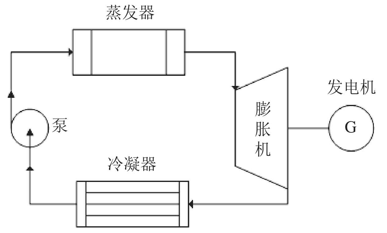
3.2 Organic Rankine cycle
The residual heat in the system is a stable low-temperature heat source, and the organic Rankine cycle (ORC) is a way to fully utilize the heat in the low-temperature heat source. The organic Rankine cycle is a Rankine cycle of low boiling organic compounds, which can convert low-grade thermal energy into high-grade electrical energy. The system diagram of the organic Rankine cycle is shown in Figure 3.
Based on the heat storage parameters of the energy storage system and considering the end difference of the heat exchanger, the organic matter evaporation temperature is set at 180 ℃, the condensation temperature is set at 35 ℃, the available hot water flow rate is 34 t/h, the inlet temperature is 190 ℃, and the return water temperature is 50 ℃. Select three commonly used working fluids for the organic Rankine cycle: trichlorofluoromethane (R11), trifluorodichloroethane (R141b), and trifluorotrichloroethane (R113). The physical parameters of the three organic compounds are listed in Table 5.
Use software to calculate the work capacity of each organic substance under the waste heat parameters of the energy storage system, and ultimately select the working medium with the strongest work capacity. The inlet and outlet pressures of the expander are the evaporation pressure corresponding to the organic substance at 180 ℃ and the condensation pressure corresponding to 35 ℃, respectively.
The power generation of each organic compound is shown in Figure 4.
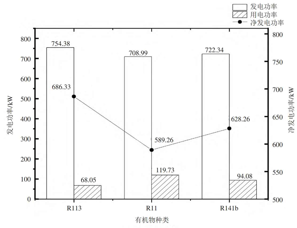
The power generation is the organic Rankine cycle system power generation, the power consumption is the electrical power consumed by the system’s cycle compression pump, and the net power generation is the net output power of the system’s power generation minus the power consumed by the cycle compression pump. From Figure 4, it can be seen that among the three organic compounds, when consuming the same heat storage medium, the net power generation from high to low is R113, R141b, and R11, respectively. The net power generation is 686.33 kW, 628.26 kW, and 589.26 kW, respectively. Therefore, when coupling an organic Rankine cycle power generation system and selecting R113 as the working fluid of the cycle, the system efficiency is maximized.
4.Conclusion
Fully utilizing the waste heat in the compressed air energy storage system can effectively improve the efficiency of the system. This article takes a 100 MW compressed air energy storage system as the research object, and analyzes the impact of increasing the inlet temperature of the expander and coupling the organic Rankine cycle power generation system on the efficiency of the energy storage system.
1) Increasing the inlet temperature of the expander can fully utilize the residual heat of the system and increase the power generation of the system. However, as the inlet temperature increases, the water side flow rate of the heater increases, and the original system’s hot water supply is insufficient to meet the heating demand. Additionally, as the exhaust temperature increases, the exhaust loss increases;
2) The coupled organic Rankine cycle power generation system can fully utilize the waste heat of the system, and there are differences in the power performance of different working fluids. The working fluid with the strongest power generation ability is R113, with a net power generation of 686.33 kW. The system can provide 3431.65 kWh of electricity during a single storage and discharge process.