
In recent years, the photovoltaic industry has developed rapidly. Power electronic equipment is one of the basic equipment in the photovoltaic industry, and studying the operating characteristics of power electronic equipment has become an important direction. The inverter is the core component of solar power generation technology, which directly reflects the operation status of the power generation system. Therefore, online monitoring of the operation of solar inverters has important practical significance. During the operation of solar inverters, their switching devices are most prone to faults, which directly affect the DC output current. Therefore, monitoring the DC output current of the solar inverter can reflect whether the operating status of the solar inverter is normal.
Studied the principle and application prospects of LoRa communication technology, proposed the design circuit of Hall current sensor and its application method for transmission lines, mainly introduced the design, application, and analysis of a solar inverter monitoring system based on software platform. Based on the above research, this article proposes an online monitoring method for solar inverters based on LoRa spread spectrum communication technology. The application of LoRa communication technology in the field of solar inverter monitoring has the characteristics of long-distance and low power consumption. At the same time, real-time Hall current sensor data on the DC side of the solar inverter can be obtained. The data is transmitted to computer software and processed through noise reduction and filtering to obtain the operating status of the solar inverter, thus achieving the monitoring purpose.
1. Overall structure of the monitoring system
1.1 Basic Model Design of the System
Adopting the latest Internet of Things technology – perception terminals based on LoRa technology. This structure mainly consists of three parts: perception layer, network layer, and application layer. The perception layer includes solar inverters and LoRa monitoring modules, the network layer includes LoRa gateways and servers, and the application layer includes computer processing and monitoring status prediction. The current sensor of its LoRa monitoring module monitors the DC output data of the solar inverter in real-time, and sends it to the gateway through LoRa RF. The gateway then reaches the server through 4G and Ethernet, and finally analyzes the monitoring status through computer processing.
1.2 Improving the Design of Hall Current Sensors
This article designs a self powered current sensor, consisting of a Hall current sensor, collector, signal conditioning circuit, power management, and LoRa transmission module, as shown in Figure 1. This sensor deduces the current value to be measured by measuring the magnetic induction intensity. The Hall element is made by fully utilizing the Hall effect. When placed in a magnetic field, the Hall element (1, 2) receives a current I, and the other side (3, 4) generates a Hall electromotive force.
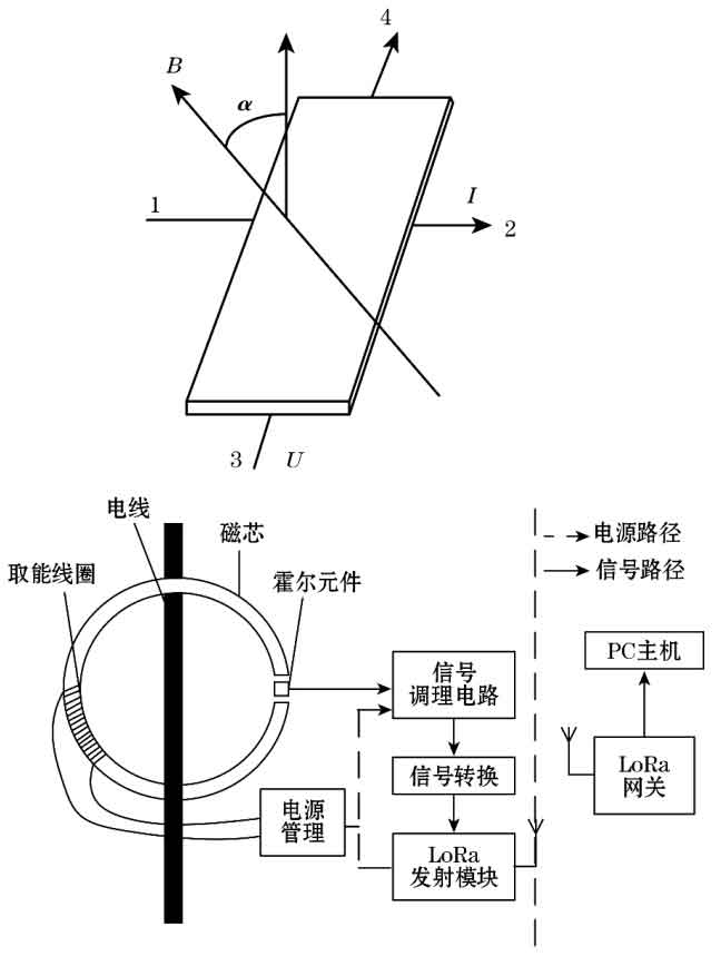
In the formula: B is the external magnetic induction intensity; Δ Is the thickness of the device; RH is the Hall coefficient.
The Hall element is used to detect the output current of the solar inverter, and the signal is transmitted to the LoRa transmission module through modulation and demodulation; The collector is used for collecting electromagnetic energy from the coil, while the power management stores energy. The coil continuously charges the energy storage supercapacitor as a backup, and the energy storage element reaches a certain value for energy supply. Current sensors and other components start working, and the PC host can display and transmit data. As shown in Figure 2, the position information of the current sensor in the actual solar inverter can be displayed in real-time by the current sensor, which has practical monitoring significance.
1.3 Power management module
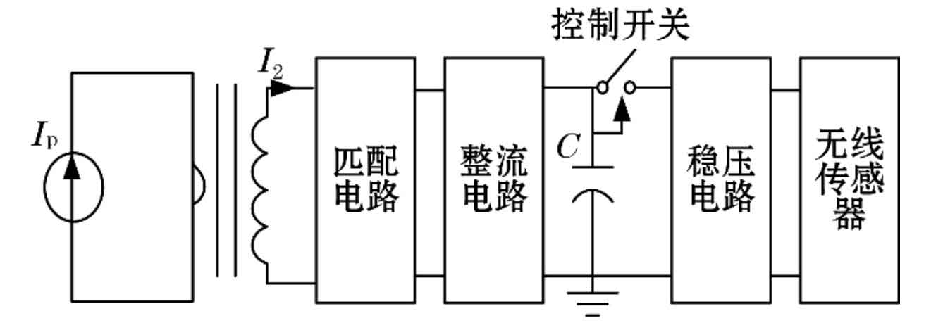
The power management module is shown in Figure 3, including the matching circuit section, rectification circuit section, voltage stabilizing section, wireless sensor section, and switch control. The energy storage supercapacitor is charged by the induction voltage of the energy harvesting coil through the matching circuit and rectification circuit. When the voltage of the supercapacitor energy storage element reaches the control voltage, the switch is opened, and the energy storage capacitor provides a constant working voltage to the wireless sensor through the voltage stabilizing circuit. The device operates normally.
1.4 RF Matching Circuit Design
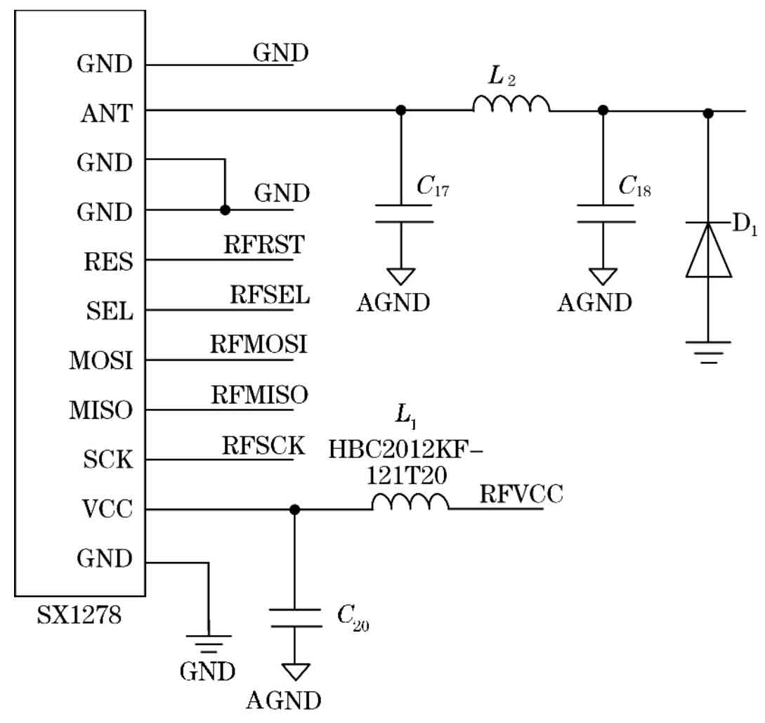
The impedance of an antenna is influenced by various factors, including installation angle, housing, and flooring. The RF matching circuit is shown in Figure 4. This circuit can correct the antenna to its normal value when it deviates from the normal range. In general, the antenna impedance is about 50 Ω, and C17 and C18 in the figure do not require welding; L2 can be used with a 220 pF capacitor, 1 nH inductor, or 0 resistor. Only in special circumstances will matching adjustments occur, such as inside the antenna mold, small antenna volume, or the need to strengthen high-order harmonic suppression.
2. LoRa RF chip and testing
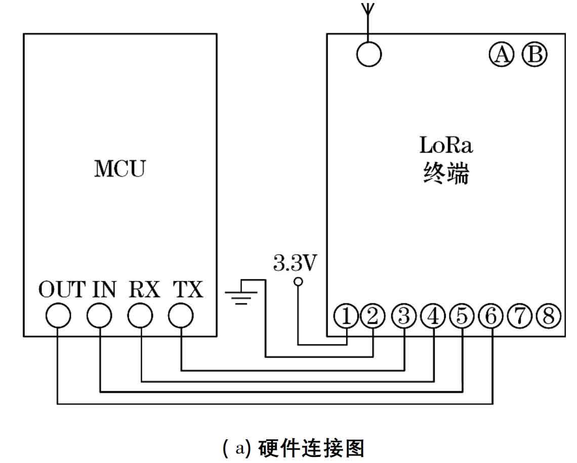
This article adopts the wireless communication module iWL881A, which has efficient and powerful IoT functions as its operating system Contiki. The central processor is an ultra-low power STM8L151C8 processor, and the RF chip uses SX1278. SX1278 is a half duplex low intermediate frequency transmission transceiver, whose RF signal needs to pass through a single ended low noise amplifier. Then the signal is transformed into a differential signal to improve the second harmonic, which is then converted into an in-phase intermediate frequency orthogonal signal. After ADC data conversion, subsequent data processing is carried out in the digital field. The state machine also includes gain control, receiving signal strength labeling, and frequency correction. The frequency synthesizer generates local oscillator frequencies for use by the receiver and transmitter. SX1278 has three types of RF power amplifiers, which are compatible with RFO_ LF, RFO_ HF, PA_ BOOST pin connection. Its frequency range is 169-915 MHz. The SX1278 also includes 2 timing benchmarks, 1 RC oscillator, and 1 32 MHz crystal oscillator. All important parameters of the RF front-end and digital state machine can be configured through the SPI interface, and the configuration register of SX1278 can be accessed through SPI. The hardware connection diagram is shown in Figure 5 (a).
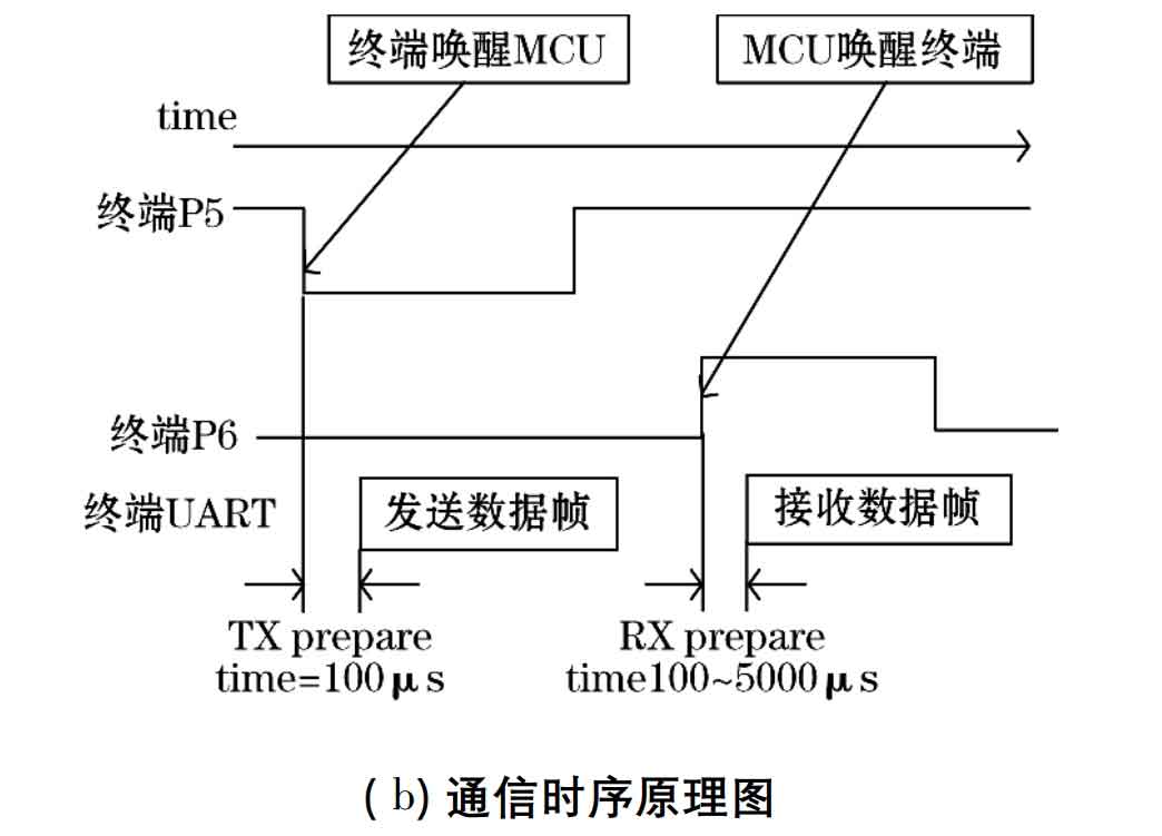
The specific communication process is as follows: The LoRa terminal is an ultra-low power consumption product that is usually in a sleep state for a long time. The MCU needs to be awakened before sending UART data. The terminal’s P5 pin is generally at high potential, and when sending a data frame, the pin is pulled down to start data transmission through the UART port. After the data transmission is completed, the terminal then sets P5 at high potential. MCU sets P6 pin as high potential to wake up the terminal, with a delay of 100 μ s. The MCU can transmit data from the UART. After the data transmission is completed, the MCU sets P6 to low potential, as shown in the schematic diagram in Figure 5 (b).
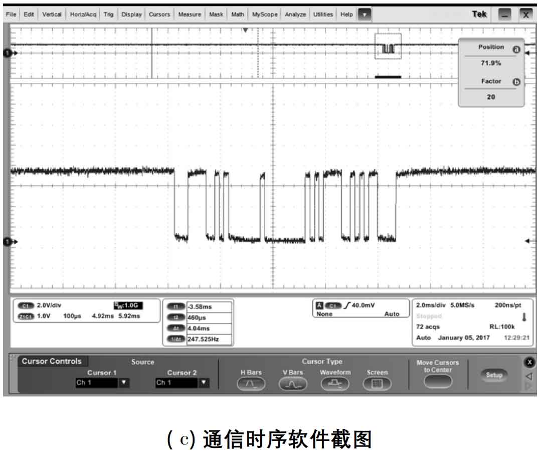
The communication performance of the system is a prerequisite for monitoring. Using the iWL881A wireless communication module, the communication data between the gateway and nodes is LoRaWAN data type, with 23 bytes when the node is connected to the network and 13 bytes during normal communication. Set the LoRaWAN confirmation byte of the node to true, and send data packets 5 times per second after entering the network. After the node receives the true frame, the LED light will turn on red and the serial port line will be connected, Check the signal strength of the received data packet at that time; The gateway adopts an 8 dBm antenna with a frequency of 476.5 MHz and a low-power transmission power of 17 dBm. Place the testing equipment in a distance of 5 km and receive the signal as shown in Figure 5 (c).
3. Upper computer software
The computer software part consists of two parts: the remote monitoring part and the on-site part. The on-site part integrates collection equipment for data storage and real-time status monitoring, and drives LoRa collection equipment to send data to the remote monitoring location of the monitoring station through Ethernet. The remote monitoring part conducts data analysis and comparison, and draws conclusions for display.
4. Experiment and Analysis
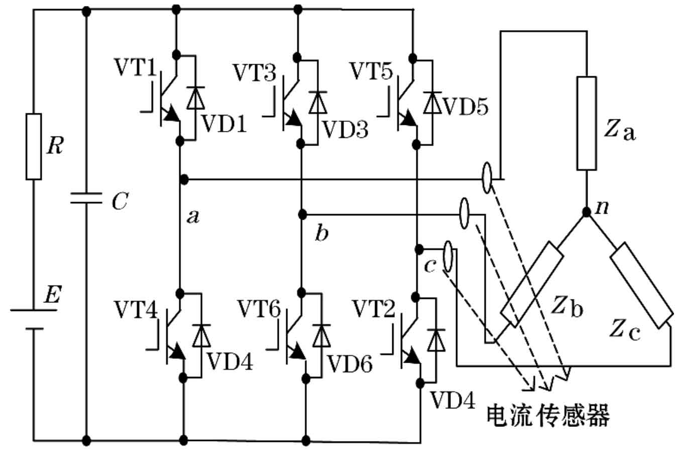
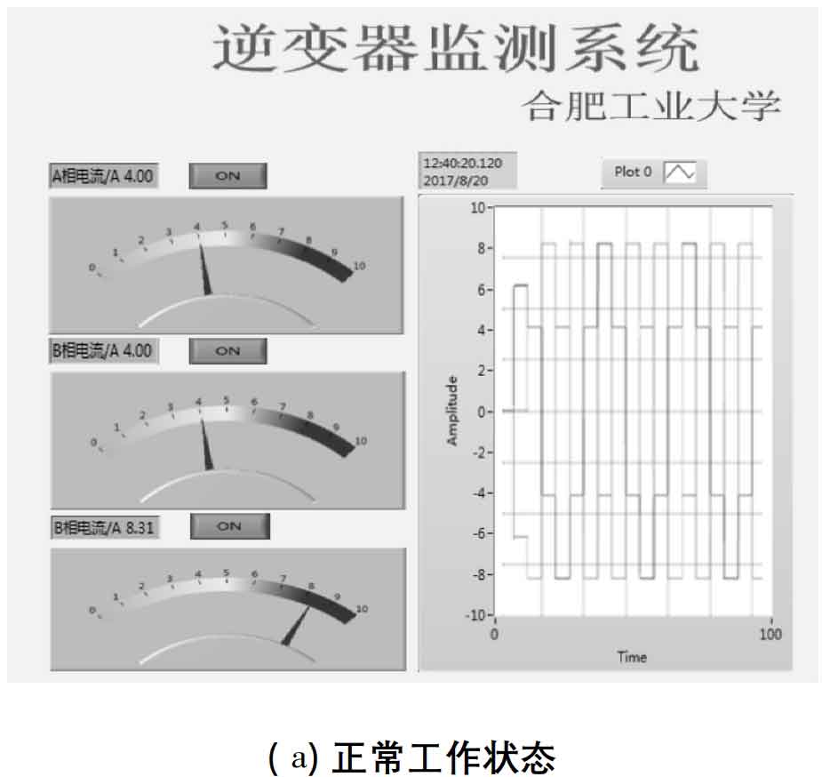
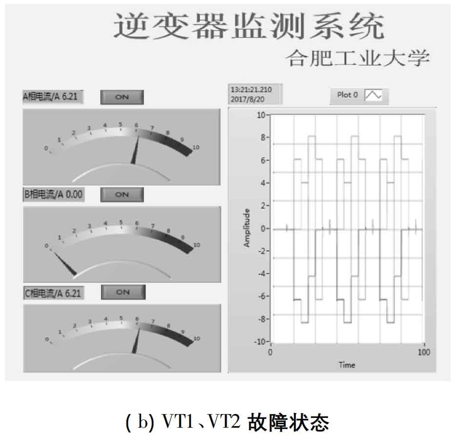
This article adopts a voltage type three-phase bridge solar inverter device, with the switching device IGBT constantly operating and its AC side current also dynamically changing. The current signal contains important information that can be used as fault diagnosis for voltage source three-phase bridge solar inverters. Monitoring and analyzing the AC side current signal during the operation of a voltage type three-phase bridge solar inverter can quickly understand the working conditions of the input side, output side, power electronic switching devices, driving signals, etc. of the solar inverter, and timely detect the fault signs of each part. The voltage type three-phase bridge square wave solar inverter in this article operates in a 180 ° conductive mode, with a load of 8 Ω resistive load, a power supply voltage of 100 V, and a resistance of 1 μ Ω, the parameters of the IGBT module and diode are the default values, and the parallel capacitance value is 10 μ F. Square wave pulse parameters: with a peak value of 1, a period of 0.02 seconds, and a pulse width of 50, the phase delay time is 0, 0.003 33, 0.006 667, 0.01, 0.013 33, 0.016 667. For the sake of representativeness in the experiment, this article monitored the output DC side current of solar inverters that were operating normally and had VT1 and VT2 open circuits simultaneously. The software screenshot is shown in Figure 6. Based on the relationship between the three-phase output DC side current and different fault characteristics, the quantitative relationship shows a certain pattern. Based on this, the working status of solar inverters can be determined, achieving the purpose of monitoring.
5. Conclusion
Solar inverters are a crucial part of solar power generation. Once a malfunction occurs, timely handling can minimize losses. Therefore, this article proposes a state monitoring technology for solar inverters. Due to the different operating states of solar inverters, the output current will have different characteristics.
The improved Hall current sensor can detect current signals in real-time and transmit them to computer software for processing through LoRa communication technology, analyzing the working status of the solar inverter. The later experiments provided two current signal maps under different states, which can directly reflect the normal operation of the solar inverter and verify the feasibility of the monitoring method.