
In modern urban drainage systems, intercepting wells play a critical role in separating stormwater from sewage, especially in combined sewer networks. These structures are often located in remote areas, such as fields or along riverbanks, far from centralized power grids. As a result, providing reliable electricity for their operation—such as powering gates and control systems—poses significant challenges. Traditional grid connections are impractical due to high infrastructure costs and logistical issues. This is where the off grid solar system emerges as an optimal solution. By harnessing solar energy, these systems ensure uninterrupted power supply while aligning with sustainable development goals. In this article, I explore the design, implementation, and benefits of using an off grid solar system for intercepting wells, focusing on technical aspects like component selection, energy storage, and system optimization.
The core advantage of an off grid solar system lies in its independence from the main electrical grid, making it ideal for isolated applications. For intercepting wells, which have low power demands but require consistent operation, solar power offers a cost-effective and environmentally friendly alternative. I will delve into the design principles, structural considerations, and electrical configurations that make such systems viable. Additionally, I will present detailed calculations, tables, and formulas to illustrate key concepts, ensuring a comprehensive understanding of how an off grid solar system can be tailored to meet specific load requirements. Throughout this discussion, the term “off grid solar system” will be emphasized to highlight its relevance and repeated application in this context.
Intercepting wells typically handle functions like gate control for sewage and stormwater separation. For instance, during dry weather, sewage gates remain open to direct wastewater to treatment plants, while stormwater gates close. In rainy conditions, stormwater gates open to prevent overflow, and a limited amount of sewage is intercepted. The primary loads include gate actuators (short-duration loads) and programmable logic controllers (PLCs) for automation (continuous loads). A typical load profile might involve a stormwater gate with a power rating of 2.2 kW, a sewage gate at 1.1 kW, a PLC at 50 W, and auxiliary loads around 80 W. Based on operational patterns, the daily energy consumption can be calculated. Assuming the stormwater gate operates for 0.5 hours during rainfall, the total daily energy demand is derived as follows:
$$ Q_L = P_1 \times t_1 + P_2 \times t_2 $$
Where \( Q_L \) is the daily energy consumption in watt-hours (Wh), \( P_1 \) represents the continuous loads (e.g., PLC and auxiliaries at 130 W), \( t_1 \) is the operation time for continuous loads (24 hours), \( P_2 \) is the power of intermittent loads like the stormwater gate (2200 W), and \( t_2 \) is their operation time (0.5 hours). Thus:
$$ Q_L = 130 \times 24 + 2200 \times 0.5 = 3120 + 1100 = 4220 \, \text{Wh} $$
This energy requirement forms the basis for designing the off grid solar system, ensuring it can reliably power the intercepting well without grid support. The system must account for seasonal variations, battery storage, and efficient energy conversion, all of which I will address in subsequent sections.
Design Principles for the Off-Grid Solar System
When implementing an off grid solar system for intercepting wells, several design principles guide the process to ensure efficiency, reliability, and environmental harmony. First, the system must integrate seamlessly with the surrounding landscape. For example, solar panels can be mounted on structures like配电柜顶棚 (distribution cabinet shelters), serving dual purposes: generating electricity and providing protection from weather elements. This approach minimizes visual impact and maintains the natural aesthetics of areas like riverbanks or fields. Second, the technology selected—such as inverters and charge controllers—should be mature and robust, featuring comprehensive protection mechanisms to guarantee long-term operation under varying conditions. These principles underscore the practicality of an off grid solar system in remote settings.
Another key consideration is scalability and maintenance. Since intercepting wells are often distributed unevenly along waterways, each off grid solar system must be customized to local load profiles and solar insolation levels. For instance, in regions with high rainfall, the system might prioritize battery capacity to handle prolonged cloudy periods. Conversely, in sunny areas, panel sizing could be optimized for higher energy yield. By adhering to these principles, the off grid solar system not only meets operational demands but also reduces lifecycle costs through minimal upkeep and modular components.
System Configuration and Components
An off grid solar system comprises several interconnected components: solar panels, charge controllers, batteries, inverters, and the load. For intercepting wells, the system is designed to convert solar energy into usable AC power for gates and control systems. The schematic below illustrates the energy flow:
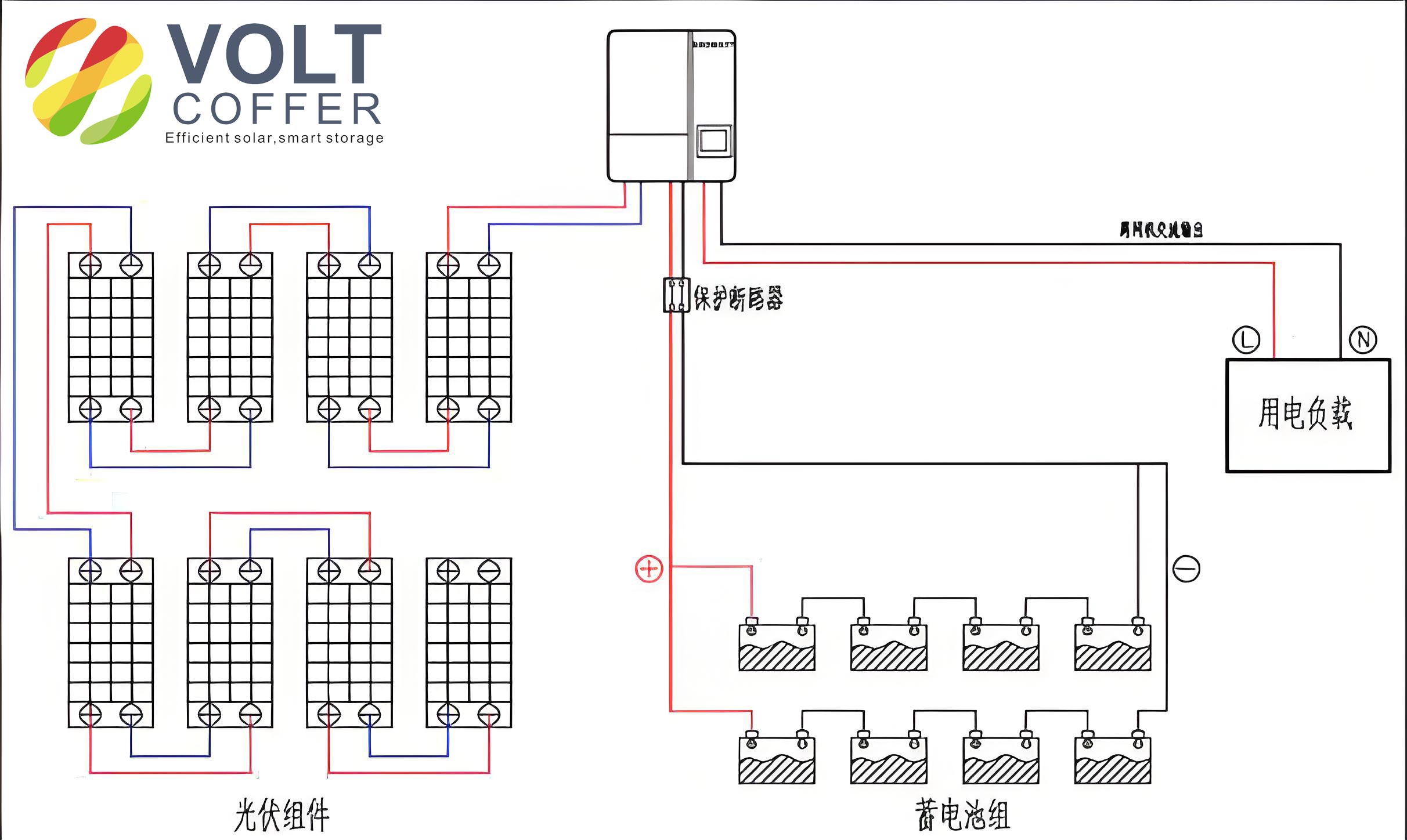
Solar panels capture sunlight and convert it to DC electricity, which is regulated by a charge controller to prevent battery overcharging. The energy is stored in batteries for use during non-sunny periods. An inverter then converts DC to AC power, supplying the loads. This configuration ensures that the off grid solar system operates autonomously, even during nighttime or inclement weather. Key parameters, such as panel orientation and battery capacity, are calculated based on site-specific data to maximize efficiency.
Structural Design and Installation
The structural design of an off grid solar system focuses on stability, orientation, and integration with existing infrastructure. Solar panels are typically installed on mounting structures that double as protective covers for equipment like distribution cabinets. The tilt angle of the panels is critical for optimizing energy capture. Based on geographic latitude, the optimal angle can be determined using established guidelines, as shown in Table 1.
| Latitude Range of Installation | Recommended Panel Tilt Angle |
|---|---|
| 0° to 25° | Equal to latitude |
| 26° to 40° | Latitude plus 5° to 10° |
| 41° to 55° | Latitude plus 10° to 15° |
| Above 55° | Latitude plus 15° to 20° |
For instance, in a location at 23°N latitude, the panels should be tilted at approximately 23° to achieve balanced energy production across seasons. This tilt maximizes solar irradiance absorption, enhancing the performance of the off grid solar system. Additionally, the mounting structure must withstand environmental stresses, such as wind speeds up to 40 m/s, and be securely anchored to foundations. Elevating components like batteries above ground level (e.g., by 50 cm) prevents water damage from flooding, a common issue in riverine areas. Aesthetic considerations, such as using wooden enclosures to hide metal supports, ensure the off grid solar system blends with natural surroundings.
Electrical Design and Calculations
The electrical design of an off grid solar system involves sizing components to meet energy demands reliably. This includes selecting batteries, solar panels, and inverters based on mathematical models. I will outline the step-by-step calculations for a typical intercepting well application.
Battery Sizing
Batteries are the energy reservoir in an off grid solar system, storing electricity for use when solar generation is insufficient. The capacity depends on daily energy consumption, autonomy days (number of days the system can operate without sun), inverter efficiency, and battery depth of discharge. The formula for battery capacity \( Cap \) in ampere-hours (Ah) is:
$$ Cap = \frac{Q_L \times D}{\eta_1 \times \eta_2 \times V} $$
Where \( Q_L \) is the daily energy consumption (4220 Wh), \( D \) is the autonomy days (typically 3 days for reliability), \( \eta_1 \) is the battery depth of discharge (0.85 for longevity), \( \eta_2 \) is the inverter efficiency (0.85), and \( V \) is the system voltage (48 V for typical off-grid setups). Plugging in the values:
$$ Cap = \frac{4220 \times 3}{0.85 \times 0.85 \times 48} = \frac{12660}{34.68} \approx 365 \, \text{Ah} $$
To account for margins and ensure reliability, a 400 Ah battery bank is selected. Using 12 V, 400 Ah gel batteries—known for their durability and low maintenance—four units are connected in series to achieve 48 V, 400 Ah. This configuration supports the off grid solar system during extended cloudy periods, ensuring continuous operation of intercepting well loads.
Solar Panel Sizing
Solar panels must generate enough energy to recharge the batteries and power the loads daily. The sizing considers peak sun hours, panel efficiency, and system losses. For a site with an average of 4 peak sun hours per day, the daily energy output per panel can be estimated. Using a 300 W panel with specifications from Table 2:
| Parameter | Value |
|---|---|
| Dimensions (mm) | 1650 × 992 × 40 |
| Maximum Power (Wp) | 300 |
| Optimum Operating Voltage (Vmp) | 32.6 |
| Optimum Operating Current (Imp) | 9.21 A |
| Open-Circuit Voltage (Voc) | 40.1 V |
| Short-Circuit Current (Isc) | 9.72 A |
The daily energy production per panel \( Q_A \) in ampere-hours (Ah) is calculated as:
$$ Q_A = I \times t \times a_1 \times a_2 $$
Where \( I \) is the panel’s optimum current (9.21 A), \( t \) is the peak sun hours (4 h), \( a_1 \) is the loss factor (0.9 for soiling and wiring losses), and \( a_2 \) is the coulombic efficiency (0.9 for battery charging). Thus:
$$ Q_A = 9.21 \times 4 \times 0.9 \times 0.9 = 29.84 \, \text{Ah} $$
To determine the number of panels needed, we first compute the daily energy requirements in Ah. The load demand \( Q_2 \) is:
$$ Q_2 = \frac{Q_L}{V} = \frac{4220}{48} \approx 88 \, \text{Ah} $$
Additionally, the battery recharge needs after autonomy days must be considered. If the interval between cloudy periods \( \Delta t \) is 10 days, and the battery depth of discharge is 50%, the daily energy to recharge the battery \( Q_1 \) is:
$$ Q_1 = \frac{P_B \times D_B}{\Delta t} = \frac{400 \times 0.5}{10} = 20 \, \text{Ah} $$
Thus, the total daily energy requirement is \( Q_1 + Q_2 = 20 + 88 = 108 \, \text{Ah} \). The number of panels in parallel \( N_2 \) is:
$$ N_2 = \frac{Q_1 + Q_2}{Q_A} = \frac{108}{29.84} \approx 3.62 $$
Rounding up, four panels are required in parallel to meet the energy needs. This ensures the off grid solar system can handle variations in solar input and load demand.
Inverter Selection
The inverter converts DC power from the batteries to AC power for the loads. Key parameters include rated capacity, input voltage, and efficiency. For intercepting wells, a 10 kW inverter is suitable, as it can handle peak loads like gate motors. Specifications from Table 3 ensure compatibility:
| Parameter | Value |
|---|---|
| Rated Capacity (kW) | 10 |
| Input Voltage | 48 V DC |
| Inverter Efficiency | 85% |
| Dimensions (mm) | 590 × 470 × 730 |
The inverter must include features like overload protection, automatic voltage regulation, and surge suppression to safeguard the off grid solar system. Its efficiency of 85% is factored into the battery and panel sizing calculations to ensure overall system reliability.
Lightning Protection and Grounding
To ensure the off grid solar system operates safely in all weather conditions, robust lightning protection and grounding are essential. This involves multiple layers of defense. First, surge protection devices (SPDs) are installed at the distribution cabinet to divert transient voltages from lightning strikes. Second, the inverter itself should include built-in surge arrestors to protect sensitive electronics. Finally, all metallic components—such as solar panel mounts and equipment enclosures—must be bonded to a common grounding system tied to the intercepting well’s earth electrode. This grounding network dissipates fault currents and minimizes electrocution risks, enhancing the durability of the off grid solar system in outdoor environments.
Monitoring and Control Systems
Modern off grid solar systems incorporate monitoring solutions to track performance and diagnose issues remotely. Using communication protocols like RS-485 or Ethernet, data on energy generation, battery state of charge, and load consumption are transmitted to a central platform. For instance, a supervisory control and data acquisition (SCADA) system can provide real-time alerts for maintenance, such as panel cleaning or battery replacement. This proactive approach maximizes the uptime of the off grid solar system and allows operators to optimize energy usage based on historical trends. In intercepting wells, where reliability is critical, such monitoring ensures that gate operations remain uninterrupted, even in isolated locations.
Economic and Environmental Benefits
Deploying an off grid solar system for intercepting wells offers significant economic advantages by eliminating grid connection costs, which can be prohibitively high in remote areas. Moreover, solar power reduces operational expenses through minimal fuel and maintenance requirements. Environmentally, the system cuts carbon emissions and aligns with global renewable energy initiatives. Over its lifespan, an off grid solar system can achieve a positive return on investment, especially when incentives for green technology are considered. For municipal projects, this translates to improved public service without straining budgets.
Challenges and Future Directions
Despite its benefits, the off grid solar system faces challenges like initial capital outlay and space requirements for panels and batteries. However, advancements in photovoltaic efficiency and energy storage, such as lithium-ion batteries, are mitigating these issues. Future iterations could integrate hybrid systems with wind or diesel backups for enhanced reliability. Research into smart grids and IoT-based management will further optimize the off grid solar system for urban water infrastructure, making it a cornerstone of sustainable development.
Conclusion
In summary, the off grid solar system provides a viable and efficient power solution for intercepting wells in remote or grid-inaccessible locations. Through careful design—incorporating optimal panel orientation, adequately sized batteries, and robust inverters—the system meets the energy demands of gate controls and automation. The use of mathematical models and tables ensures precision in component selection, while protective measures guarantee longevity. As renewable energy adoption grows, the off grid solar system will play an increasingly vital role in environmental engineering, demonstrating how innovation can address practical challenges while promoting sustainability.