
As an engineer with extensive experience in renewable energy applications, I have witnessed the growing importance of off grid solar systems in providing electricity to remote and underserved areas. Unlike grid-tied systems, which feed power back to the utility grid, off grid solar systems operate independently, making them ideal for locations such as mountainous regions, deserts, islands, and rural villages in developing countries where conventional power infrastructure is absent. In this article, I will delve into the principles, design considerations, and future trends of off grid solar systems, drawing from my practical engineering background. I will emphasize key aspects like environmental adaptability, load management, and technological advancements, using tables and formulas to summarize critical data. The term “off grid solar system” will be frequently highlighted to underscore its relevance.
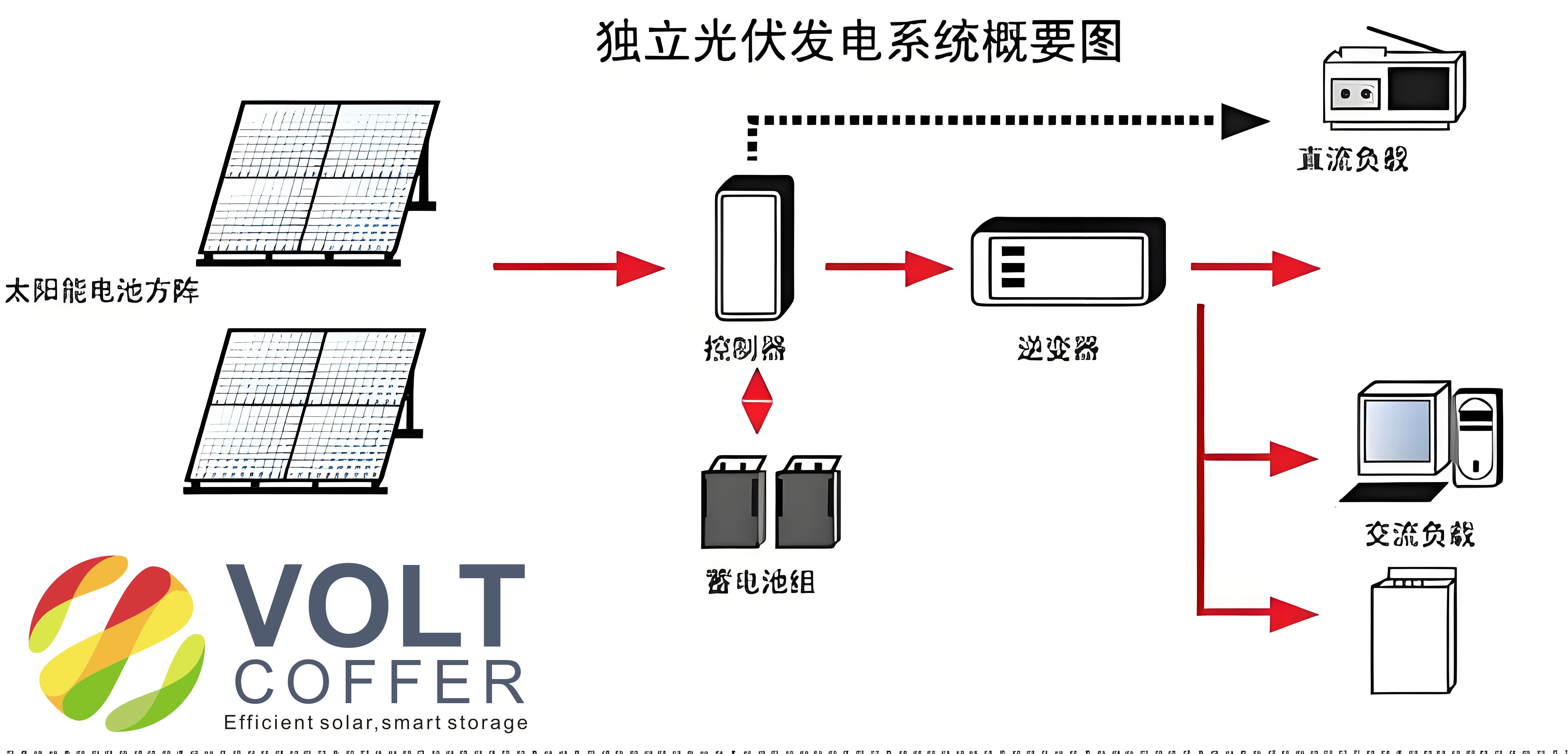
The core of an off grid solar system lies in its ability to harness solar energy and store it for later use, ensuring a reliable power supply even during nighttime or cloudy conditions. A typical off grid solar system comprises several essential components: the solar array, photovoltaic controller, battery bank, and off-grid inverter. The solar array, consisting of photovoltaic panels, converts sunlight into direct current (DC) electricity through the photovoltaic effect. For instance, in crystalline silicon panels, the “photovoltaic effect” generates a voltage across the PN junction due to charge accumulation, which can be modeled by the equation for photocurrent: $$I_{ph} = q \cdot G \cdot A \cdot (1 – R)$$ where \(I_{ph}\) is the photocurrent, \(q\) is the electron charge, \(G\) is the irradiance, \(A\) is the area, and \(R\) is the reflectance. This DC power is then regulated by a photovoltaic controller, which often incorporates Maximum Power Point Tracking (MPPT) to optimize energy extraction. The controller charges the battery bank using a multi-stage charging method, such as the three-stage approach illustrated in a table later. Finally, the off-grid inverter converts the stored DC energy into alternating current (AC) for powering various loads. Throughout this process, the off grid solar system must be designed to handle diverse environmental challenges and load demands.
In my design practice, I have found that the photovoltaic controller is a critical component in an off grid solar system. It typically employs a BUCK circuit with MPPT control to efficiently transfer energy from the solar panels to the battery bank. The three-stage charging process—bulk, absorption, and float—ensures optimal battery health and longevity. For example, the battery voltage and current during these stages can be summarized as follows:
| Stage | Voltage (V) | Current (I) | Description |
|---|---|---|---|
| Bulk | Rising to set point | Constant at max | Rapid charging until voltage threshold |
| Absorption | Constant at set point | Gradually decreasing | Maintains voltage to complete charge |
| Float | Lower maintenance level | Minimal | Prevents overcharging and sustains charge |
The mathematical representation of the MPPT algorithm can be expressed using the perturbation and observation method: $$\Delta P = P_{new} – P_{old}$$ where \(P_{new}\) and \(P_{old}\) are the power measurements at consecutive time steps, and the duty cycle of the BUCK converter is adjusted to maximize power output. This efficiency is crucial for the overall performance of the off grid solar system, as it directly impacts energy harvest and storage.
When designing an off grid solar system, environmental factors play a pivotal role. In harsh environments like deserts, islands, or high-altitude regions, the system must withstand conditions such as temperature extremes, dust, salt spray, and humidity. For instance, in desert applications, diurnal temperature variations can lead to condensation inside equipment, compromising insulation and safety. To address this, I recommend enhancing the Ingress Protection (IP) rating of enclosures and implementing protective measures for internal components. The heat dissipation in such systems must be carefully managed to prevent overheating, which can be modeled using the thermal equation: $$Q = h \cdot A \cdot \Delta T$$ where \(Q\) is the heat transfer rate, \(h\) is the heat transfer coefficient, \(A\) is the surface area, and \(\Delta T\) is the temperature difference. In many projects, I have integrated cooling solutions like air conditioning to maintain optimal operating temperatures, especially for high-heat components like battery banks in an off grid solar system.
Another key consideration in off grid solar system design is the choice of voltage configuration for power distribution. This decision affects safety, cost, and maintenance. For example, in some regions, a TN-S system (with separate protective and neutral wires) is preferred for its safety benefits, particularly in areas with sensitive electronic devices. However, its higher installation costs may deter investors. Alternatively, a TN-C system (with combined protective and neutral wires) offers economic advantages but poses higher risks in fault conditions. The selection should balance initial investment with long-term reliability, as summarized below:
| System Type | Advantages | Disadvantages | Suitability |
|---|---|---|---|
| TN-S | High safety, reduced shock risk | Higher cost, complex installation | Dense populations, sensitive equipment |
| TN-C | Cost-effective, simple design | Potential fault propagation | Remote areas with budget constraints |
Lightning protection is also vital for an off grid solar system, especially when using overhead lines for power transmission. Based on standards like the Building Electronic Information System Lightning Protection Technical Code, I advise installing lightning arrestors and improving insulation at vulnerable points. The energy dissipated by a surge protector can be calculated as: $$E = \frac{1}{2} C \cdot V^2$$ where \(E\) is the energy, \(C\) is the capacitance, and \(V\) is the voltage. This ensures the system’s resilience against natural disturbances, enhancing the reliability of the off grid solar system.
Load diversity is a significant challenge in off grid solar system applications. Communities may use a mix of resistive, inductive, and capacitive loads, such as lights, air conditioners, and refrigerators, which can cause current surges during startup. To manage this, I incorporate design margins and control logic to stagger device activation, often using Energy Management Systems (EMS). For inductive loads, which can generate back-emf during shutdown, I include absorption circuits to prevent voltage spikes that could damage components like IGBTs. The formula for inductive kickback voltage is: $$V_L = L \cdot \frac{di}{dt}$$ where \(V_L\) is the induced voltage, \(L\) is the inductance, and \(\frac{di}{dt}\) is the rate of current change. Additionally, using isolation transformers in off-grid inverters helps mitigate interference between the inverter and loads, a practice I strongly recommend for improving system stability in an off grid solar system.
Looking ahead, the future of off grid solar systems is closely tied to advancements in battery technology and monitoring systems. Traditionally, lead-acid batteries were common, but they suffer from limited cycle life, environmental concerns, and charging inefficiencies. In contrast, lithium-ion batteries offer superior performance, with higher charge rates, longer lifespan, and better environmental profiles. For instance, the charging current for lead-acid batteries is typically around 0.1C, requiring over 10 hours for a full charge, whereas lithium batteries can handle 0.5C to 1C, allowing faster charging during limited sunlight hours. The cycle life comparison can be expressed using the Arrhenius equation for battery degradation: $$N = N_0 \cdot e^{-\frac{E_a}{kT}}$$ where \(N\) is the cycle life, \(N_0\) is the initial cycle count, \(E_a\) is the activation energy, \(k\) is Boltzmann’s constant, and \(T\) is the temperature. This shows that lithium batteries endure more cycles, making them ideal for daily charge-discharge in an off grid solar system.
| Parameter | Lead-Acid | Lithium-Ion |
|---|---|---|
| Charging Current | ~0.1C | 0.5C to 1C |
| Cycle Life | 500-1000 cycles | 2000-5000 cycles |
| Environmental Impact | High (toxic materials) | Lower (recyclable) |
| Parallel Groups | Up to 3 recommended | Up to 10+ with BMS |
Moreover, the integration of Battery Management Systems (BMS) into the off grid solar system allows for precise control over charging and discharging, enhancing safety and efficiency. The state of charge (SOC) can be estimated using formulas like: $$\text{SOC} = \text{SOC}_0 – \frac{1}{C_n} \int I \, dt$$ where \(\text{SOC}_0\) is the initial state, \(C_n\) is the nominal capacity, and \(I\) is the current. In remote, unattended locations, I emphasize the importance of incorporating monitoring systems that include energy meters, environmental sensors (e.g., for temperature, humidity, and smoke), and remote communication capabilities. This enables real-time data collection and alerts, ensuring proactive maintenance and reducing downtime for the off grid solar system.
In conclusion, the off grid solar system represents a transformative solution for electrifying isolated regions, driven by continuous improvements in technology and design. From my experience, these systems have evolved to address diverse environmental and load challenges, with lithium batteries and advanced monitoring paving the way for greater reliability and efficiency. As we move forward, the widespread adoption of off grid solar systems will not only meet basic energy needs but also foster economic growth and social development in underserved communities. I am confident that with ongoing innovation, the off grid solar system will play an increasingly vital role in the global energy landscape.