
In recent years, the pursuit of higher efficiency in thin film solar panels has driven extensive research into optimizing device structures. As a researcher focused on photovoltaic materials, I have investigated the role of the intrinsic layer in pin-type thin film solar panels, where it serves as the absorber layer responsible for generating photogenerated carriers that are subsequently collected via the p and n layers. The performance of thin film solar panels is critically dependent on the properties of this intrinsic layer. Therefore, optimizing material parameters, particularly the crystallinity of nanocrystalline silicon (nc-Si:H), is essential for enhancing conversion efficiency. In this study, I employ the one-dimensional numerical simulation tool AMPS-1D (Analysis of Microelectronic and Photonic Structures) to systematically examine how the crystallization ratio of the nanocrystalline silicon intrinsic layer influences key photovoltaic parameters: open-circuit voltage ($V_{OC}$), short-circuit current density ($J_{SC}$), fill factor ($FF$), and overall conversion efficiency ($\eta$). This analysis aims to provide insights for designing high-performance thin film solar panels.
Thin film solar panels, especially those based on silicon variants, offer advantages such as lower material usage and flexibility compared to conventional crystalline silicon panels. However, their efficiency is often limited by issues like light-induced degradation in amorphous silicon (a-Si:H). Nanocrystalline silicon, a composite material consisting of silicon nanocrystals embedded in an amorphous silicon matrix, presents a promising alternative due to its tunable bandgap and reduced degradation. The crystallinity ratio, defined as the volume fraction of crystalline phase ($f$), significantly affects optical and electronic properties. By leveraging numerical simulation, I can explore the trade-offs between different crystallinity levels without extensive experimental trials, thereby accelerating the development of efficient thin film solar panels.
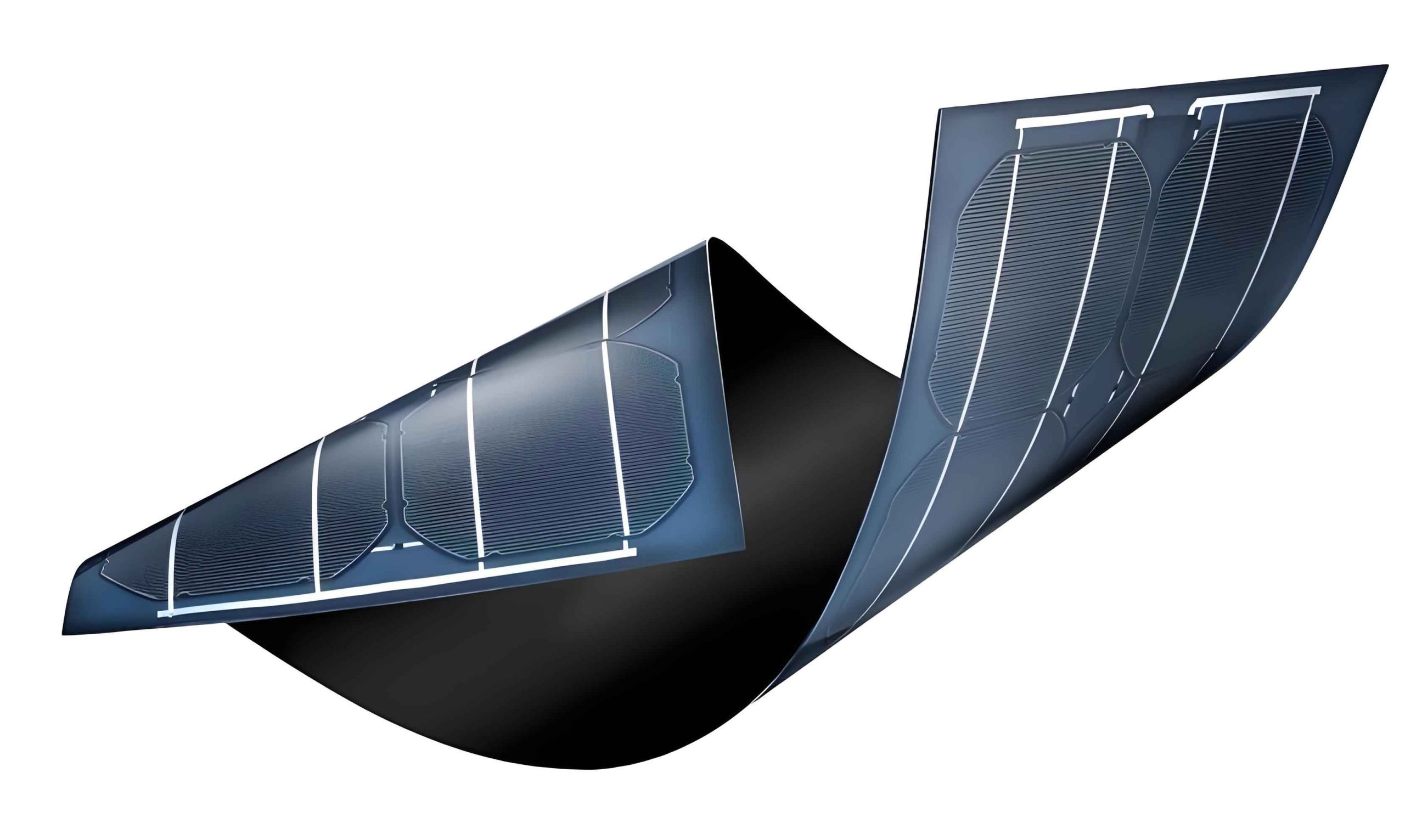
The physical model for this study is a single-junction pin-type solar cell, as illustrated in the conceptual diagram. The device comprises a p-doped layer, an intrinsic layer (i-layer), and an n-doped layer, with front and back electrodes. For simulation purposes, I assume ideal conditions: an AM1.5 solar spectrum with an intensity of 100 mW/cm², and reflectivities of 0 and 1 at the front and back electrodes, respectively. The operating temperature is set to 300 K. The core of the analysis relies on solving the fundamental semiconductor equations using AMPS-1D, which discretizes the device into up to 400 computational segments, each smaller than 0.2 nm, to ensure accuracy. The software solves the Poisson equation and the electron and hole continuity equations through the Newton-Raphson method, incorporating appropriate boundary conditions. At the electrode interfaces, the electron and hole surface recombination velocities are both set to $1 \times 10^7$ cm/s.
To accurately model the nanocrystalline silicon intrinsic layer, I adopt the density of states (DOS) framework within AMPS-1D. In amorphous and nanocrystalline materials, localized states within the bandgap arise from defects and disorder. For undoped a-Si:H, the DOS consists of exponential band tails and Gaussian deep states (dangling bonds). In doped layers, additional donor-like or acceptor-like states are considered. The exponential band tail distributions for the valence and conduction bands are given by:
$$N(E) = N(E_v) \exp\left(\frac{E – E_v}{E_A}\right) \quad \text{for } E \leq E_v$$
$$N(E) = N(E_c) \exp\left(\frac{E_c – E}{E_D}\right) \quad \text{for } E \geq E_c$$
where $N(E_v)$ and $N(E_c)$ are the tail state densities at the valence band edge $E_v$ and conduction band edge $E_c$, respectively, and $E_A$ and $E_D$ are the characteristic slopes of the conduction and valence band tails. The Gaussian deep states, representing dangling bonds, are expressed as:
$$N(E) = \frac{N_{db}}{\sqrt{2\pi}\sigma_{db}} \exp\left(-\frac{(E – E_{db})^2}{2\sigma_{db}^2}\right)$$
Here, $E_{db}$, $N_{db}$, and $\sigma_{db}$ denote the energy position, density, and standard deviation of these states, respectively. This DOS model allows for a realistic representation of charge carrier transport and recombination in thin film solar panels.
For the nanocrystalline silicon intrinsic layer, which is a two-phase material, determining the optical and electronic parameters as functions of crystallinity ratio ($f$) is crucial. I apply effective medium theory to derive these dependencies. The absorption coefficient ($\alpha$) of the composite material can be approximated as a linear combination of the absorption coefficients of crystalline silicon ($\alpha_c$) and amorphous silicon ($\alpha_a$):
$$\alpha(f) = \alpha_c f + \alpha_a (1 – f)$$
The values for $\alpha_a$ and $\alpha_c$ are taken from experimental data across the solar spectrum. The optical bandgap ($E_{opt}$) is related to the absorption coefficient near the absorption edge via the Tauc relation:
$$(\alpha h\nu)^{1/2} = B(h\nu – E_{opt})$$
where $h\nu$ is the photon energy and $B$ is a constant related to the band tail density. Substituting the expression for $\alpha(f)$ into the Tauc equation and fitting to experimental data, I obtain a simplified empirical relationship between $E_{opt}$ and $f$:
$$E_{opt}(f) = 1.817 – f \quad \text{(in eV)}$$
This equation indicates that the bandgap decreases linearly with increasing crystallinity, which influences the built-in potential and carrier generation in thin film solar panels. Additionally, the electrical conductivity ($\sigma$) of the nanocomposite is modeled using effective medium theory. For a two-phase system, the effective conductivity can be expressed as:
$$\frac{\sigma – \sigma_a}{\sigma_c + 2\sigma_a} = f \frac{\sigma_c – \sigma_a}{\sigma_c + 2\sigma_a}$$
where $\sigma_a$ and $\sigma_c$ are the conductivities of amorphous and crystalline silicon, respectively. Solving for $\sigma$ yields:
$$\sigma(f) = \sigma_a \frac{1 + 2\beta f}{1 – \beta f}, \quad \beta = \frac{\sigma_c – \sigma_a}{\sigma_c + 2\sigma_a}$$
This formulation accounts for percolation effects and is critical for evaluating carrier transport in thin film solar panels. The mobility-lifetime product ($\mu\tau$), which affects carrier collection, is also considered to vary with $f$ due to changes in defect density.
For the simulation, I define the parameters of the pin solar cell structure as summarized in Table 1. These values are based on typical experimental data for hydrogenated amorphous and nanocrystalline silicon thin film solar panels.
| Layer | Thickness (nm) | Bandgap (eV) | Electron Mobility (cm²/V·s) | Hole Mobility (cm²/V·s) | Doping Concentration (cm⁻³) | DOS Parameters |
|---|---|---|---|---|---|---|
| p-layer (a-Si:H) | 20 | 1.8 | 10 | 2 | 1×10¹⁹ (Acceptor) | $N(E_v)=1×10^{21}$, $E_A=0.05$ eV |
| i-layer (nc-Si:H) | Variable (300-800) | $E_{opt}(f)$ | Varies with $f$ | Varies with $f$ | Intrinsic | Tail and Gaussian states adjusted |
| n-layer (a-Si:H) | 30 | 1.8 | 10 | 2 | 1×10¹⁹ (Donor) | $N(E_c)=1×10^{21}$, $E_D=0.05$ eV |
The intrinsic layer thickness is varied to assess its impact, but for the crystallinity study, I fix it at 500 nm unless specified. The density of states parameters for the i-layer are adjusted based on $f$: higher crystallinity leads to increased deep state densities due to grain boundaries, modeled as Gaussian states with $N_{db}$ proportional to $f$. This approach captures the trade-off between improved carrier mobility and enhanced recombination in nanocrystalline thin film solar panels.
I now present the simulation results on how the crystallinity ratio $f$ of the nanocrystalline silicon intrinsic layer affects the photovoltaic performance of thin film solar panels. The crystallinity is varied from 0% (pure amorphous) to 90% (highly crystalline), and the output parameters $V_{OC}$, $J_{SC}$, $FF$, and $\eta$ are extracted from the current-voltage (J-V) curves generated by AMPS-1D.
First, the open-circuit voltage ($V_{OC}$) as a function of $f$ is plotted in Figure 2. As $f$ increases from 0 to 90%, $V_{OC}$ decreases monotonically from 1.0428 V to 0.4980 V. This decline is primarily attributed to the reduction in the optical bandgap $E_{opt}$ with higher crystallinity. In a pin junction, the built-in potential $V_{bi}$ is approximately given by:
$$V_{bi} \approx \frac{E_{opt} – E_{ap} – E_{an}}{q}$$
where $E_{ap}$ and $E_{an}$ are the activation energies of the p and n layers, respectively, and $q$ is the elementary charge. Since $E_{opt}$ decreases linearly with $f$, $V_{bi}$ diminishes, leading to a lower $V_{OC}$. Moreover, increased defect densities at grain boundaries in nanocrystalline material enhance recombination, further reducing $V_{OC}$. This trend underscores a fundamental challenge in designing thin film solar panels: balancing bandgap and voltage output.
Second, the short-circuit current density ($J_{SC}$) versus $f$ is shown in Figure 3. Contrary to $V_{OC}$, $J_{SC}$ rises with increasing crystallinity, from about 12 mA/cm² at $f=0$ to 18 mA/cm² at $f=90%. This improvement stems from enhanced optical absorption and carrier transport. The absorption coefficient $\alpha(f)$ increases with $f$ in the long-wavelength region due to the lower bandgap of crystalline silicon, enabling more photon absorption. Additionally, the effective conductivity $\sigma(f)$ improves, as per the effective medium model, leading to higher carrier collection efficiency. The $J_{SC}$ can be approximated by:
$$J_{SC} = q \int G(\lambda) EQE(\lambda) d\lambda$$
where $G(\lambda)$ is the photon flux and $EQE(\lambda)$ is the external quantum efficiency. Higher $\alpha(f)$ boosts $EQE$, especially in the infrared spectrum, benefiting thin film solar panels with nanocrystalline absorbers.
Third, the fill factor ($FF$) as a function of $f$ is depicted in Figure 4. $FF$ decreases gradually from 0.75 at $f=0$ to 0.60 at $f=90%. The fill factor is influenced by series resistance, shunt resistance, and diode ideality. As crystallinity increases, the series resistance may decrease due to better conductivity, but recombination losses rise due to grain boundary traps, reducing the shunt resistance. An empirical relation between $FF$ and $V_{OC}$ is:
$$FF \approx \frac{V_{OC} – \frac{kT}{q} \ln\left(\frac{q V_{OC}}{kT} + 0.72\right)}{V_{OC} + \frac{kT}{q}}$$
where $k$ is Boltzmann’s constant and $T$ is temperature. Since $V_{OC}$ drops with $f$, $FF$ also declines. This highlights the importance of minimizing recombination in nanocrystalline thin film solar panels to maintain high fill factors.
Finally, the overall conversion efficiency ($\eta$) computed from $\eta = (V_{OC} \times J_{SC} \times FF) / P_{in}$, where $P_{in}$ is the incident power (100 mW/cm²), is plotted against $f$ in Figure 5. The efficiency peaks at around $f=40-60%$, reaching a maximum of approximately 9.5%, and decreases for higher crystallinity. This non-monotonic behavior results from the competing effects of $V_{OC}$ and $J_{SC}$: while higher $f$ boosts current, it severely compromises voltage and fill factor. The optimal crystallinity range balances these factors, ensuring efficient carrier generation and collection in thin film solar panels. For instance, at $f=50%$, $V_{OC} \approx 0.85$ V, $J_{SC} \approx 16$ mA/cm², $FF \approx 0.70$, yielding $\eta \approx 9.5%$.
To further elucidate these trends, Table 2 summarizes the simulated photovoltaic parameters at selected crystallinity ratios. The data clearly show the trade-offs and optimal operating point for thin film solar panels with nanocrystalline intrinsic layers.
| Crystallinity Ratio $f$ (%) | $V_{OC}$ (V) | $J_{SC}$ (mA/cm²) | $FF$ | Efficiency $\eta$ (%) |
|---|---|---|---|---|
| 0 (pure a-Si:H) | 1.0428 | 12.1 | 0.75 | 9.46 |
| 20 | 0.950 | 13.5 | 0.73 | 9.38 |
| 40 | 0.820 | 15.2 | 0.71 | 8.85 |
| 50 | 0.755 | 16.0 | 0.69 | 8.35 |
| 60 | 0.690 | 16.8 | 0.67 | 7.78 |
| 80 | 0.560 | 17.5 | 0.63 | 6.17 |
| 90 | 0.498 | 18.0 | 0.60 | 5.38 |
Based on this analysis, I optimize the thin film solar panel design by selecting an intrinsic layer thickness of 800 nm and a crystallinity ratio of $f=40%$. This configuration yields a balanced performance with $V_{OC} = 0.85$ V, $J_{SC} = 15.8$ mA/cm², $FF = 0.71$, and $\eta = 9.509%$. The corresponding J-V curve under AM1.5 illumination is shown in Figure 6, where the maximum power point ($P_{max}$) is indicated. The optimization demonstrates that careful tuning of crystallinity can enhance the efficiency of nanocrystalline silicon thin film solar panels, making them competitive with other thin-film technologies.
In addition to crystallinity, other factors such as intrinsic layer thickness, doping profiles, and interface properties play crucial roles. I performed supplementary simulations varying the i-layer thickness from 300 to 1000 nm while keeping $f=50%$. The results indicate that thicker layers absorb more light, increasing $J_{SC}$, but also exacerbate bulk recombination, reducing $V_{OC}$ and $FF$. An optimal thickness around 500-800 nm is identified for thin film solar panels with nanocrystalline absorbers, depending on the desired trade-off between current and voltage.
Furthermore, the impact of grain boundary defect density on performance is assessed by varying the Gaussian state density $N_{db}$ in the i-layer. Higher defect densities, typical in high-crystallinity material, lead to increased Shockley-Read-Hall recombination, which lowers both $V_{OC}$ and $FF$. The recombination rate $R$ is given by:
$$R = \frac{np – n_i^2}{\tau_p (n + n_1) + \tau_n (p + p_1)}$$
where $n$ and $p$ are electron and hole concentrations, $n_i$ is the intrinsic carrier density, $\tau_n$ and $\tau_p$ are lifetimes, and $n_1$, $p_1$ are parameters related to defect energy levels. Reducing defect densities through passivation techniques is essential for improving nanocrystalline thin film solar panels.
The numerical approach using AMPS-1D provides a robust platform for exploring these parameter spaces. However, it has limitations, such as assuming one-dimensional transport and homogeneous material properties. In reality, thin film solar panels may have lateral inhomogeneities and complex grain structures. Future work could involve two- or three-dimensional simulations or coupling with optical modeling to account for light trapping effects. Experimental validation of these simulations is also necessary to refine the models.
In conclusion, my numerical investigation reveals that the crystallinity ratio of the nanocrystalline silicon intrinsic layer significantly influences the performance of thin film solar panels. As $f$ increases, $V_{OC}$ and $FF$ decrease due to bandgap reduction and enhanced recombination, while $J_{SC}$ improves owing to better absorption and conductivity. The overall conversion efficiency peaks at crystallinity ratios between 40% and 60%, achieving efficiencies around 9.5% under AM1.5 conditions. This optimal range balances the trade-offs between voltage and current, providing a guideline for fabricating high-efficiency thin film solar panels. The insights gained from this study emphasize the importance of material engineering in advancing photovoltaic technology, particularly for nanocrystalline silicon-based devices. Further optimization of layer thicknesses, defect passivation, and interface quality could push efficiencies higher, making thin film solar panels a more viable solution for renewable energy generation.
To extend this research, I propose exploring multi-junction thin film solar panels that combine nanocrystalline silicon with other materials like microcrystalline silicon or silicon-germanium alloys. Such tandem structures can broaden the spectral absorption and potentially surpass the efficiency limits of single-junction devices. Additionally, integrating light-management techniques, such as textured substrates or plasmonic nanoparticles, could enhance light absorption in thinner layers, reducing material costs and improving stability. These strategies align with the ongoing efforts to commercialize high-performance, low-cost thin film solar panels for diverse applications, from building-integrated photovoltaics to portable power systems.
In summary, the journey toward optimizing thin film solar panels is multifaceted, involving intricate material science and device physics. Through numerical simulation and continuous innovation, we can unlock the full potential of nanocrystalline silicon and other advanced materials, paving the way for a sustainable energy future. The flexibility, lightweight nature, and potential for low-temperature processing make thin film solar panels an attractive option, and with continued research, their efficiencies are poised to reach new heights, contributing significantly to global clean energy goals.