
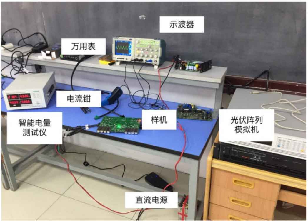
In order to verify the accuracy and feasibility of the non isolated two-stage series solar grid connected inverter designed in this article, a universal experimental platform was established in the laboratory through theoretical analysis and related design research. The platform mainly consists of a solar inverter prototype, a photovoltaic array simulator, a DC power supply, current clamps, oscilloscopes, a multimeter, and an intelligent power tester. The experimental site is shown in Figure 1.
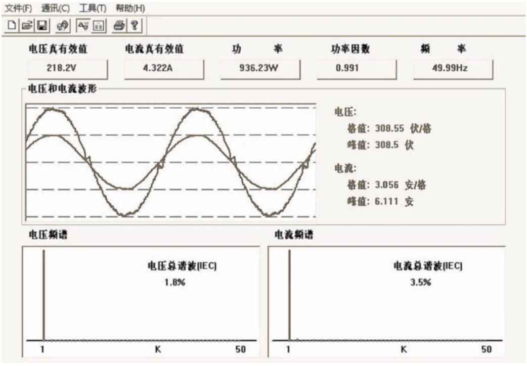
Replace the solar panel with a photovoltaic array simulator and connect it to the DC side of the solar inverter prototype. The AC side of the solar inverter prototype is connected to the intelligent power tester and the public power grid. After the system starts and reaches stability, observe the relevant test waveforms through current clamps and oscilloscopes, and connect the intelligent power tester to the upper computer. The display interface is shown in Figure 2. By organizing the parameters shown in the intelligent power tester in Figure 1 and the upper computer interface in Figure 2, the grid connected data is obtained as shown in the table. All data meet the design indicators within the allowable error range, verifying the feasibility of the non isolated two-stage series solar grid connected inverter designed in this paper. The total harmonic of the output current is 3.5%, which meets the requirement of less than 5% of the total harmonic of the grid connected current in GB/T 30427-2013.
| Effective voltage value | 218.2V |
| Power factor | 0.991 |
| Voltage peak | 308.5V |
| Frequency | 49.99Hz |
| Current effective value | 4.322A |
| Total voltage harmonics | 1.8% |
| Peak current | 6.111A |
| Total harmonic of current | 3.5% |
| Power | 936.23W |
| European efficiency | 97.22% |
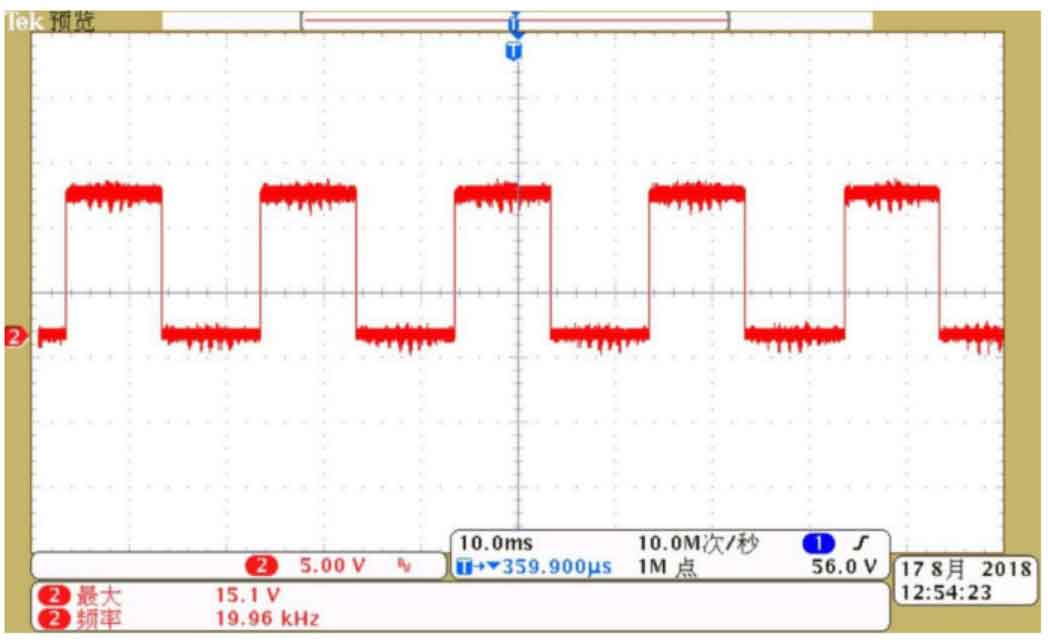
Test the relevant signal waveforms through current clamps and oscilloscopes for further verification. The driving signals of the switching devices in the front-end interleaved parallel Boost converter circuit and the back-end H6 inverter circuit are shown in Figures 3 and 4, respectively, which are consistent with theoretical analysis, and the maximum voltage of the driving signals is 15V, which meets the driving requirements.

The prototype of the solar inverter can detect the frequency and phase of the grid voltage, thereby completing the phase-locked function. Although the error is within the allowable range, there are still a small number of harmonics at the zero crossing point, and its waveform is shown in Figure 5.
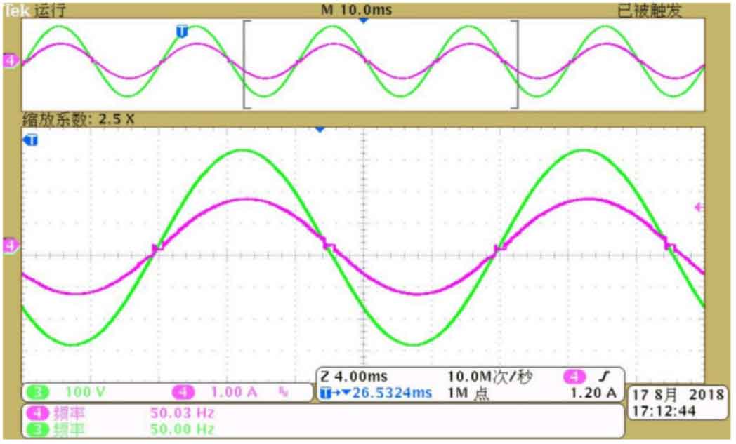
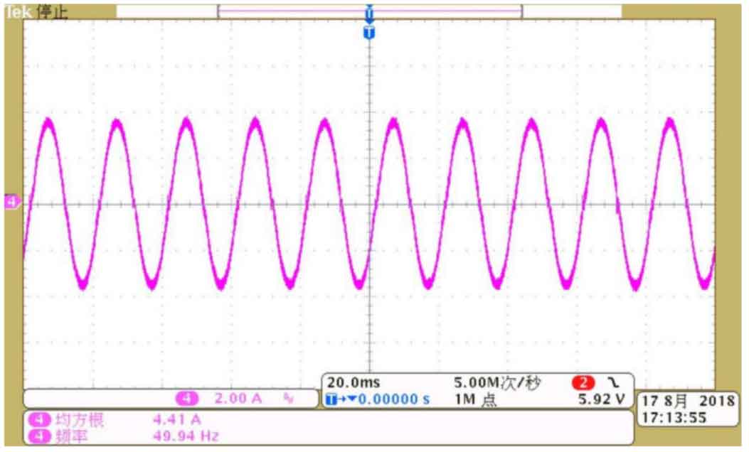
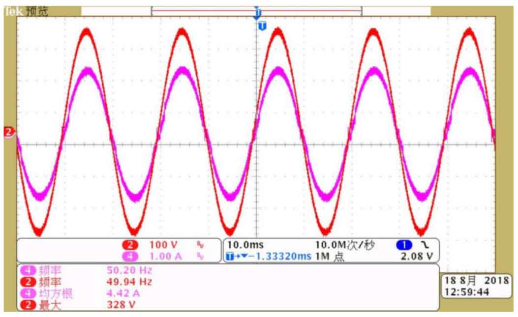
The output current waveform of the solar inverter prototype is shown in Figure 6, with a smooth sine wave shape and low distortion rate, meeting all output requirements. The output current is in the same frequency and phase as the grid voltage, with an error frequency of less than 0.3Hz, as shown in Figure 7.
Firstly, an experimental platform was built using the existing conditions and equipment in the laboratory, providing a foundation for verifying the accuracy and feasibility of the solar inverter prototype; Secondly, use the upper computer and relevant testing instruments to observe the main data and signal waveform of the solar inverter prototype; Finally, the results indicate that the solar inverter prototype can output grid connected currents that are at the same frequency and phase as the grid voltage. The total harmonic of the current meets the grid connection requirements, and the conversion efficiency and power are also relatively ideal.
Photovoltaic power generation can not only reduce environmental pollution, be safe, reliable, and renewable, but also gradually replace traditional energy to meet the electricity needs of special fields and remote areas without grid coverage. As the core of current small and medium-sized photovoltaic power plant systems, string solar inverters can solve the power generation losses caused by equipment damage and component mismatch, thereby improving power generation and achieving maximum system efficiency. They are more reliable than traditional centralized solar inverters. This article focuses on the research and design of non isolated two-stage series solar grid connected inverters. By combining professional courses such as power electronics technology, circuits, and automatic control principles, in-depth analysis is conducted on the topology structure of the front-end and back-end circuits, MPPT algorithm, current control strategy, and key issues of lock equality of solar grid connected inverters. The above simulation model is built on the Matlab/Simulink platform, and the experimental platform is finally completed. The accuracy and feasibility of the non isolated two-stage series solar grid connected inverter designed in this article are verified through simulation and experiments.
(1) Introduce the advantages of photovoltaic power generation systems and the current development status at home and abroad; Introduce the conventional classification and characteristics of solar inverters, and clarify the type of non isolated two-stage series solar grid connected inverter system studied in this article;
(2) Analyze and compare common front-end circuit topologies and their respective advantages and disadvantages, select interleaved parallel Boost converters for in-depth research and simulation, establish a mathematical model of solar cells, introduce the principle of MPPT technology and commonly used control algorithms in photovoltaic grid connected power generation, design variable step conductance increment method, and complete simulation;
(3) Analyze and compare common post stage circuit topologies and their respective advantages and disadvantages, select H6 inverter bridge for in-depth research and complete simulation. At the same time, introduce the principle of current control technology and commonly used control algorithms in photovoltaic grid connected power generation, design quasi proportional resonance control and complete simulation;
(4) Design the main circuit of the system (front-end circuit, back-end circuit, and filtering circuit) and the peripheral circuits of the system (photovoltaic array voltage and current, DC bus voltage detection circuit, grid voltage and output current detection circuit, zero crossing detection circuit, switch device drive circuit, overcurrent protection circuit, and auxiliary power supply circuit), calculate and select parameters for relevant components, and implement SPWM and digital phase-locked loop technology through TMS320F28335 control chip;
(5) Complete the construction of the experimental platform, and verify the output current of the solar inverter prototype with the same frequency and phase as the grid voltage using data from the upper computer and oscilloscope waveforms. The total harmonic of the current meets the grid connection requirements, and the conversion efficiency and power are also ideal.
With the in-depth research of relevant domestic and foreign enterprises and experts and scholars, as well as the continuous development of photovoltaic grid connected power generation technology, solar grid connected inverters are no longer satisfied with the status quo. People have higher pursuits in their functions, efficiency, and cost. However, designing a set of multi-functional, efficient, practical, and cost-effective solar grid connected inverters is not easy, and my professional ability and time are limited. There are still shortcomings in this design that need to be improved and improved:
(1) Although improvements have been made to the conventional MPPT control algorithm, when the external environment is not ideal or components are mismatched, the algorithm may not be able to make accurate and timely tracking responses. Further optimization can be achieved by combining intelligent control algorithms with cost constraints;
(2) Optimize the layout and wiring of PCBs, as well as the selection of components, to minimize electromagnetic interference between circuits and the volume of solar grid connected inverters. At the same time, improve accuracy while allowing for cost and volume, such as introducing voltage Hall sensors;
(3) Optimize the design of filtering and other circuits to improve the anti-interference performance of the system;
(4) Add data communication function to remotely monitor the data and working conditions detected by the system through Bluetooth, power carrier communication, and other methods, in order to unify the management and maintenance of multiple solar grid connected inverters.