
This article introduces three types of power vehicles: mobile flywheel energy storage emergency power vehicles, mobile solid-state switch emergency power vehicles, and mobile battery energy storage emergency power vehicles. They are mainly used in major political, economic, and cultural activities of the country to undertake extremely important political power supply guarantee tasks. A high-power multi-channel power supply vehicle has been designed, mainly for supplying power to equipment in high-altitude areas. These traditional mobile power sources are mostly organically combined with diesel power generation equipment carried by cars, which can meet the outdoor or emergency needs of users, achieve uninterrupted power supply and ensure reliable power supply in emergency situations. However, these power vehicles are expensive, and the power generation equipment mainly relies on imports and pollutes the environment. There is an urgent need for a low-cost and new type of pollution-free mobile power source.
The introduced non power point energy storage power supply mainly consists of energy storage batteries, advanced bidirectional chargers, and charging terminals integrated into standard containers, and mainly provides charging services for electric engineering vehicles on non power point construction sites. In addition, it can also be used as an energy storage power source to participate in emergency electricity consumption and peak shaving and valley filling in local power grids.
1.Composition of energy storage power sources without power supply points
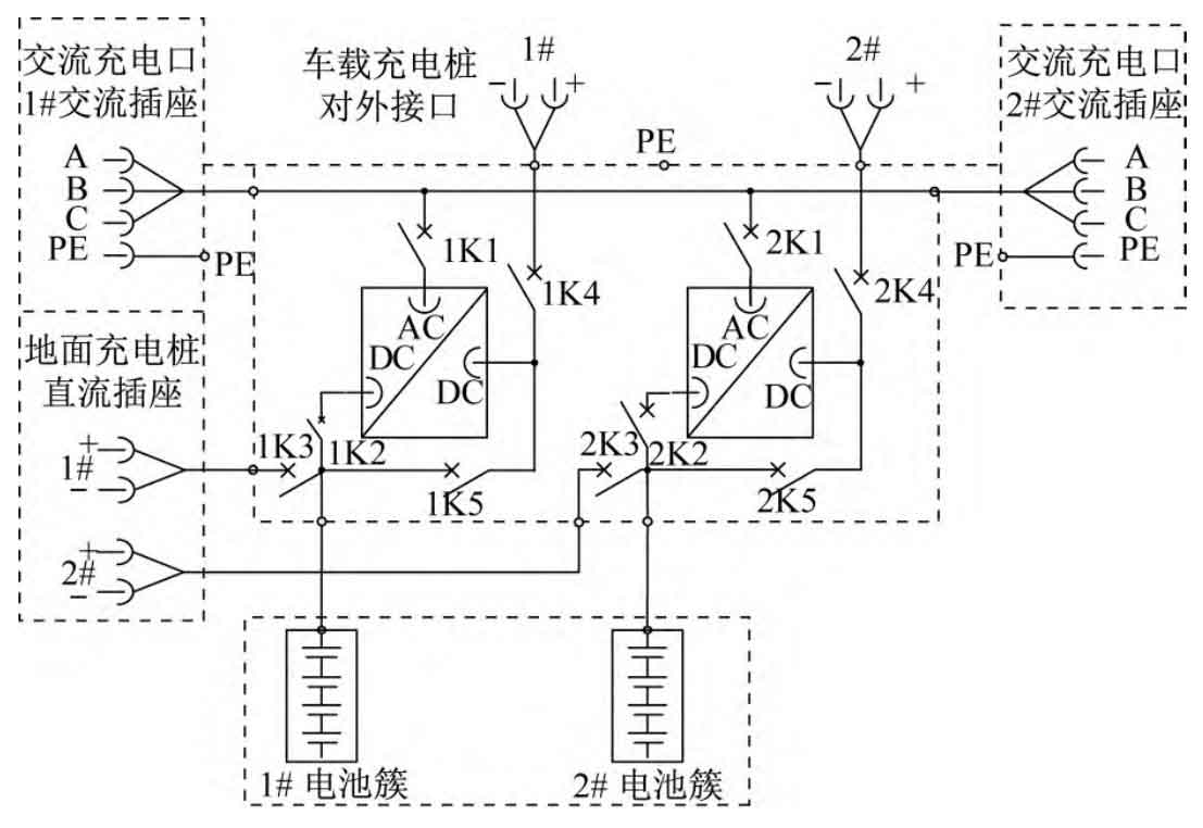
The non power point energy storage power supply adopts an outdoor box design, mainly composed of energy storage batteries, AC/DC dual input chargers, and charging terminals. The schematic diagram of an energy storage power supply without a power source is shown in Figure 1. All equipment such as energy storage batteries and chargers are fixedly arranged inside the box, with a protection level of IP56, meeting their use under different environmental conditions.
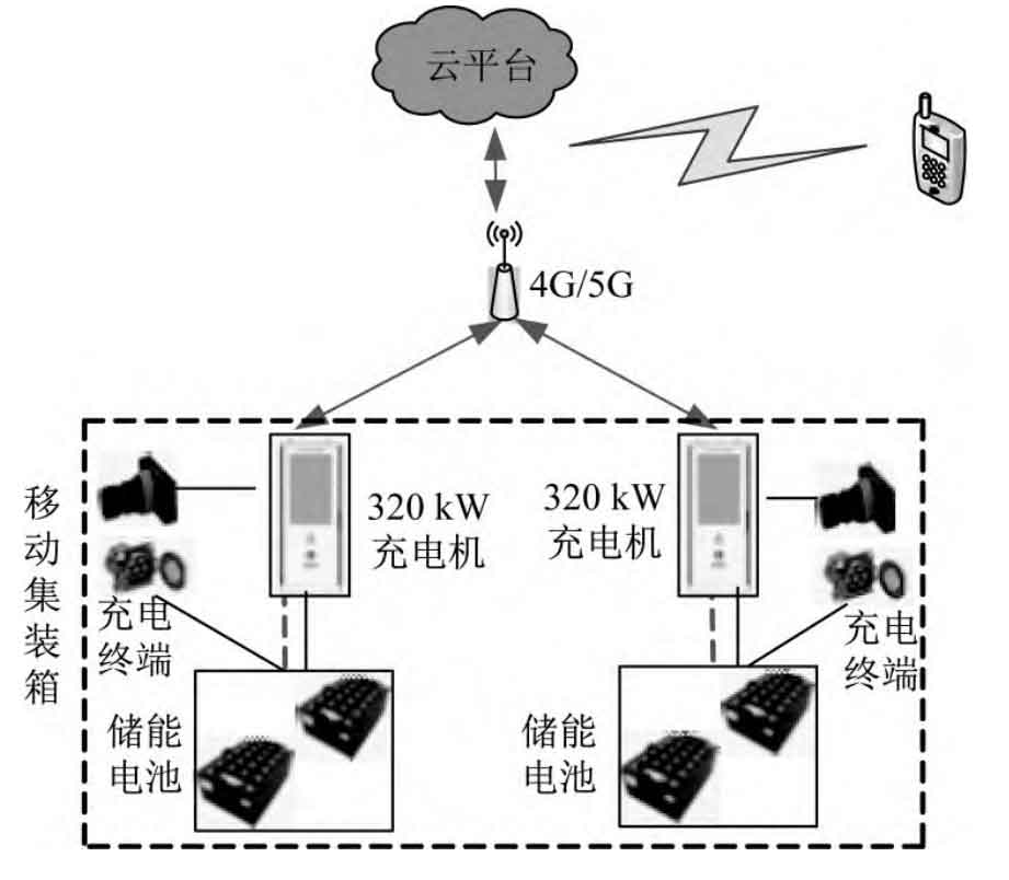
The non power point energy storage power supply adopts 4G/5G wireless communication mode to upload or receive real-time charging information and equipment status information of electric vehicles to the platform. The architecture of the energy storage power supply network without power points is shown in Figure 2.
2. Operating mode of energy storage power supply without power supply point
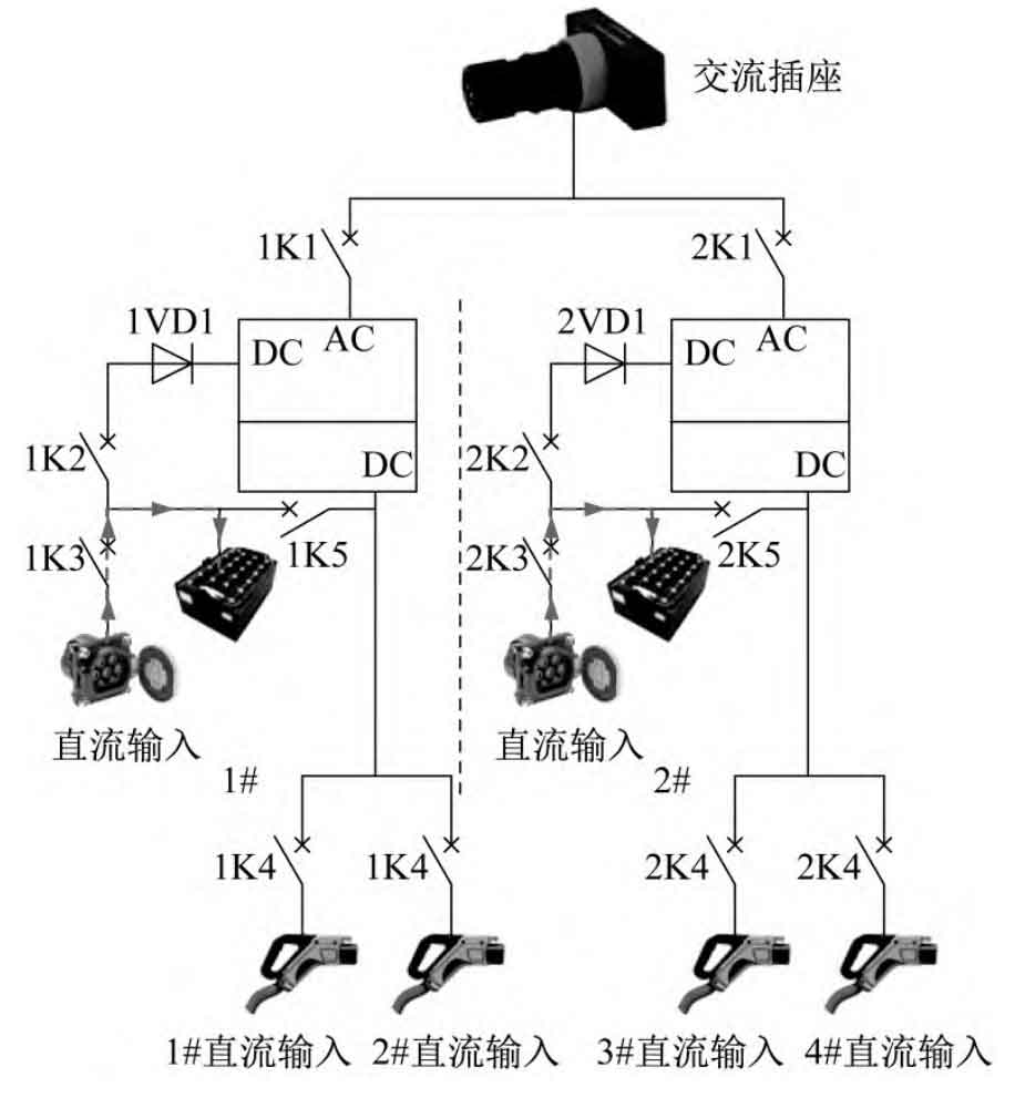
There are two operating modes for non power point energy storage power sources: one is that there is no power point on the construction site, and the non power point energy storage power source energy storage battery provides DC input for the electric engineering vehicle; Another type is that there is AC power distribution on the construction site, but the distribution capacity is insufficient. At this time, the charging system supports AC/DC and energy storage batteries to jointly provide DC input for the electric engineering vehicle. Two operating modes correspond to four operating conditions of the charging system:
| Number | Working conditions | Energy pathway |
| 1 | Communication input for charging engineering vehicles | AC socket → K1 → charger → K4 → engineering vehicle |
| 2 | Energy storage batteries charge engineering vehicles | Energy storage battery → K2 → Charger → K4 → Engineering vehicle |
| 3 | AC input for replenishing energy storage batteries | AC socket → K1 → Charger → K5 → Energy storage battery |
| 4 | DC input is used to supplement the energy storage battery | DC socket → K3 → Energy storage battery |
① Communication input for charging engineering vehicles; ② Energy storage batteries charge engineering vehicles; ③ AC input for energy storage battery charging; ④ The DC input is used to supplement the energy storage battery. The operating conditions are shown in Table 1. There are two independent electrical branches inside the non power point energy storage power supply, which can work separately under different working conditions. Single branch internal AC and DC inputs cannot be used simultaneously, K1 and K3 are interlocked.
2.1 No power point energy storage power supply for charging electric engineering vehicles
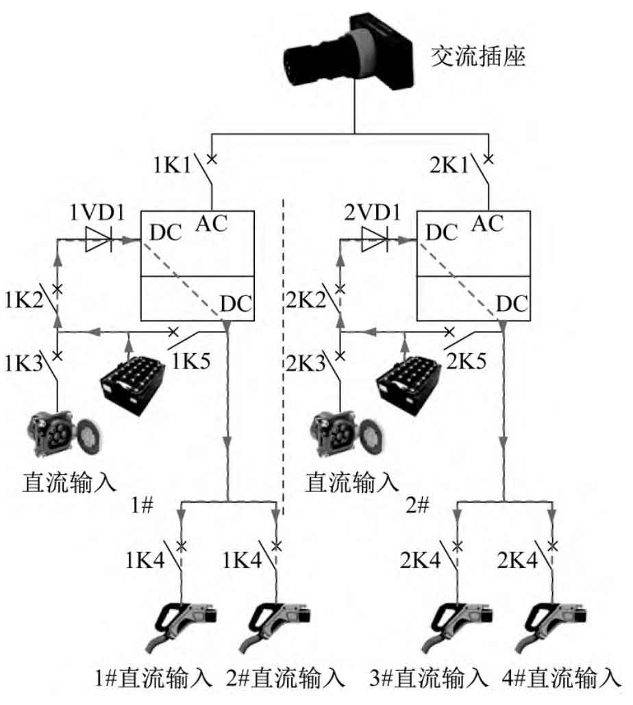
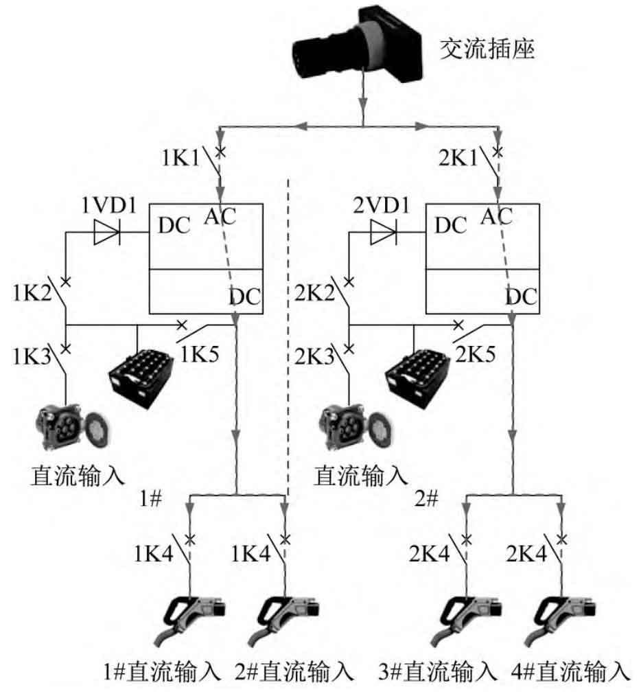
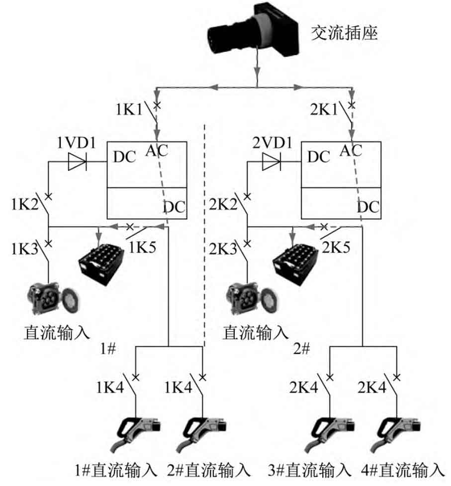
There are two ways to charge electric engineering vehicles with energy storage power sources without power points: one is to use the battery system as a DC power input to charge the electric engineering vehicle through an AC/DC dual input charger, with K2 and K4 closed (Table 1, Condition 2). The energy storage battery undergoes DC/DC conversion by a charger through K2, and then charges the electric engineering vehicle through K4. The energy storage battery charges the electric engineering vehicle as shown in Figure 3. Another method is to use an external AC power input to charge the electric engineering vehicle through an AC/DC dual input charger, with K1 and K4 closed (Table 1, Condition 1). The AC input passes through K1, and the charger performs AC/DC conversion, then outputs DC energy through K4 to charge the electric engineering vehicle. The communication input is for charging electric engineering vehicles, as shown in Figure 4.
The charging control strategy for electric engineering vehicles using non power point energy storage power sources complies with GB/T 27930-2015 “Communication Protocol between Non on-board Conductive Chargers and Battery Management Systems for Electric Vehicles”. The entire charging process includes six stages: physical connection completion, low-voltage auxiliary power on, charging handshake stage, charging parameter configuration stage, charging stage, and charging end stage.
2.2 No Power Point Energy Storage Power Supply Recharge
There are two ways to transport a non power point energy storage power source to a public charging point to recharge the energy storage battery: one is to use an external DC power input to recharge the energy storage battery through a DC socket, with K3 closed (Table 1, Condition 4). Connect the DC socket to an external power source and charge the energy storage battery through K3. The DC socket is used to recharge the energy storage battery, as shown in Figure 5. Another external AC power input is used to supplement the energy storage battery through an AC/DC dual input charger, with K1 and K5 closed (Table 1, Condition 3). The AC input passes through K1, and the charger performs AC/DC conversion. The K5 outputs DC energy to charge the energy storage battery. The AC socket is used to recharge the energy storage battery, as shown in Figure 6.
This system is designed as two independent 320 kW/345.6 kWh power supply branches, which work independently and do not interfere with each other, in accordance with GB/T 27930-2015.
2.3 Work mode priority control strategy
Priority control strategy for various working modes of energy storage power sources without power supply points: AC charging for electric engineering vehicles>Energy storage batteries charging for engineering vehicles>AC charging for energy storage batteries.
3. Experimental analysis
3.1 Prototype of Energy Storage Power Supply without Power Point
The main circuit of the test prototype consists of two sets of 320 kW chargers connected to 345.6 kWh lithium iron phosphate batteries, and accessories such as AC sockets, DC sockets, fire protection systems, lighting and security systems are installed in a 10 foot container. The prototype of an energy storage power supply without a power source is shown in Figure 7.

3.2 Analysis of experimental results
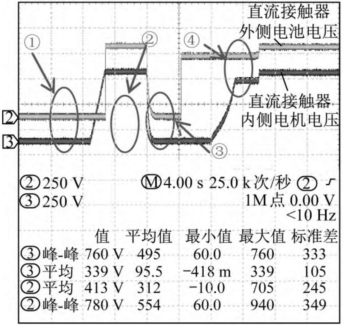
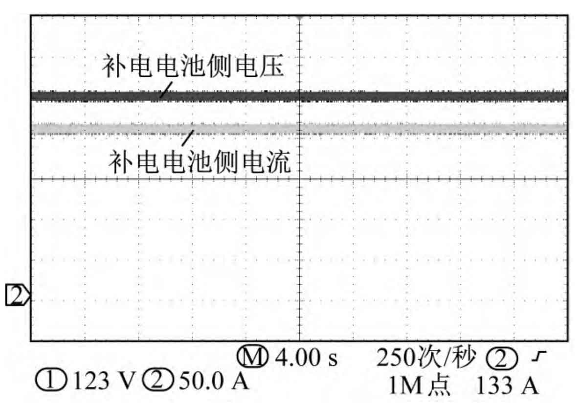
The startup process of the energy storage power supply is shown in Figure 8; The power supply process of electric engineering vehicles is shown in Figure 9; The harmonic distortion rate THD of the energy storage power supply is shown in Table 2.
| Harmonic frequency | A-phase | B-phase | C-phase |
| Hthd | 2.3 | 2.2 | 2.6 |
| H2 | 1.2 | 1.1 | 1.2 |
| H3 | 0.7 | 0.6 | 0.7 |
| H4 | 0.5 | 0.5 | 0.5 |
| H5 | 0.8 | 1.0 | 0.8 |
| H6 | 0.3 | 0.3 | 0.4 |
| H7 | 0.9 | 0.8 | 0.9 |
| H8 | 0.3 | 0.4 | 0.4 |
| H9 | 0.3 | 0.4 | 0.4 |
| H10 | 0.3 | 0.4 | 0.4 |
| H11 | 0.3 | 0.5 | 0.4 |
| H12 | 0.3 | 0.3 | 0.3 |
| H13 | 0.4 | 0.4 | 0.5 |
| H14 | 0.3 | 0.2 | 0.2 |
| H15 | 0.2 | 0.2 | 0.2 |
| H16 | 0.1 | 0.2 | 0.2 |
| H17 | 0.2 | 0.2 | 0.2 |
| H18 | 0.1 | 0.1 | 0.1 |
| H19 | 0.1 | 0.1 | 0.1 |
| H20 | 0.1 | 0.1 | 0.1 |
| H21 | 0.1 | 0.1 | 0.1 |
| H22 | 0.1 | 0.1 | 0.1 |
| H23 | 0.1 | 0.1 | 0.1 |
| H24 | 0.1 | 0.1 | 0.1 |
| H25 | 0.1 | 0.1 | 0.1 |
| H26 | 0.1 | 0.1 | 0.1 |
| H27 | 0.1 | 0.1 | 0.1 |
| H28 | 0.1 | 0.1 | 0.1 |
| H29 | 0.1 | 0.1 | 0.1 |
| H30 | 0.1 | 0.1 | 0.1 |
| H31 | 0.1 | 0.1 | 0.1 |
| H32 | 0.1 | 0.1 | 0.1 |
| H33 | 0.1 | 0.1 | 0.1 |
| H34 | 0.1 | 0.1 | 0.1 |
| H35 | 0.1 | 0.1 | 0.1 |
| H36 | 0.1 | 0.1 | 0.1 |
| H37 | 0.1 | 0.1 | 0.1 |
| H38 | 0.2 | 0.2 | 0.1 |
| H39 | 0.1 | 0.1 | 0.2 |
| H40 | 0.2 | 0.2 | 0.2 |
Figure 8 shows that after the energy storage power supply is fully connected to the interface of the electric engineering vehicle, the low-voltage auxiliary power supply circuit conducts, and insulation testing begins at point ①; After the insulation detection is completed, physically separate the insulation detection (IMD) from the strong current circuit at point ②, and put it into the discharge circuit to discharge the charging output voltage. Complete the electrical discharge at point ③; At point ④, the pre charging of the energy storage power supply is completed, and the voltage on the inside of the contactor is about 10 V lower than the voltage on the outside. Close the contactor to supply power to the electric engineering vehicle. The entire startup process of the energy storage power supply fully complies with GB/T 34657.1-2017 “Interoperability Test Specification for Conductive Charging of Electric Vehicles Part 1: Power Supply Equipment”. Figure 9 shows that the energy storage power supply continuously supplies 625 V/192 A of electrical energy to the electric engineering vehicle, ensuring stable and reliable operation. In addition, after testing and verification of the prototype, the THDA of the energy storage power supply under AC power supply is ≤ 3%, which meets the technical requirements of NB/T33001-2018 “Technical Conditions for Non on-board Conductive Chargers for Electric Vehicles”.
The charging current and state of charge (SOC) curve generated from the entire charging process data of the energy storage power supply. The charging current and SOC curve are shown in Figure 10.
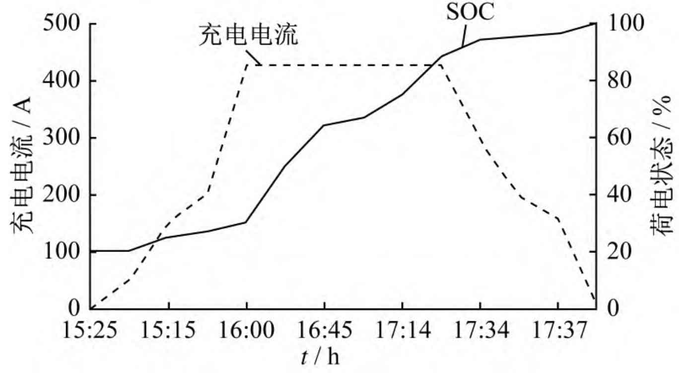
As shown in Figure 10, low current charging starts at 15:25; 16: Starting constant current charging at 00; 17: 22 enters constant voltage current limiting charging; 17: 42 power supply completed. The SOC gradually increases throughout the charging process until it reaches 100%. The data shows that the entire charging process is low current charging, followed by constant current charging, and finally entering float charging until fully charged.
4. Conclusion
This article proposes a new type of mobile energy storage power supply to supplement the power supply for power free engineering vehicles, which will face problems such as insufficient on-site distribution or inability to charge without power configuration, difficulty in charging, and environmental pollution when promoting electric engineering vehicles on a large scale in the future. Based on the application conditions on site, the priority and charging control strategies of four working modes were analyzed in detail, and a prototype was developed and tested to meet the requirements of GB/T 34657.1-2017 and NB/T 33001-2018. It can meet the charging needs of electric engineering vehicles on site and also meet the replenishment of electric engineering vehicles without power supply points. Electric engineering vehicles can work continuously and improve work efficiency by about 40%, which has a positive effect on the promotion of electric engineering vehicles.