
With the gradual reduction of traditional energy usage, the development and utilization of renewable energy is imperative. The representative renewable energy is solar energy, which is widely used in the development of renewable energy as a pollution-free green and clean energy. The new type of solar photovoltaic power generation fundamentally solves the decreasing energy demand in the world, and has been studied and gradually applied by many scholars. Among them, photovoltaic grid connected power generation is one of the main directions explored by many scholars, and the core component of photovoltaic grid connected power generation system is the solar grid connected inverter. To avoid current harmonics flowing into the grid, it is necessary to connect with the grid through filters. Therefore, improving the quality of the electricity entering the grid has become a key issue for photovoltaic grid connected power generation systems.
The switching frequency and its integer multiple frequency position of the solar inverter are the key gathering points for the high-order harmonics of the grid connected current. LLCL filter is a new type of filtering device that has superior filtering performance compared to traditional filters because it connects a small inductance value in series with the capacitor branch of the traditional LCL filter, which can form a series resonant circuit together with the capacitor. The series resonant frequency is set at the switching frequency position, which can weaken the current harmonics at the switching frequency position more, Improve the quality of current delivery to the power grid. Based on this, this article conducts research and analysis on a new type of solar single-phase solar inverter, laying the foundation for improving the stability and quality of the current transmitted to the power grid.
1. Performance analysis of a new solar single-phase solar inverter
1.1 Composition of solar photovoltaic power generation
The entire process of converting solar radiation into electrical energy through the photovoltaic effect of semiconductor materials in photovoltaic modules is called solar photovoltaic power generation. It is composed of solar photovoltaic cell arrays, battery packs, DC/AC solar inverters, and AC/DC loads, with the advantages of being noise free, pollution-free, and easy to maintain. The composition diagram of solar photovoltaic power generation.
The key to solar photovoltaic power generation is solar photovoltaic cells. Currently, there are three main types of solar photovoltaic cells, namely: monocrystalline silicon, polycrystalline silicon, and amorphous silicon. Among them, monocrystalline silicon has the highest photoelectric conversion efficiency and the most durable. Therefore, monocrystalline silicon solar photovoltaic cells are used here to design the system in this paper. The short circuit current and open circuit voltage of this battery board are 2.8 A and 11 V, respectively.
1.2 Topology structure and control strategy of single-phase grid connected circuit
1.2.1 Structure of single-phase photovoltaic grid connected system
A single-phase photovoltaic power generation grid connection system is composed of monocrystalline silicon solar photovoltaic cells, solar inverters, Boost DC/DC circuits, and control circuits. To adjust the output voltage of the solar photovoltaic array, it is necessary to adjust the duty cycle by the front-end Boost circuit to achieve the goal of tracking the maximum power point voltage; The maximum power of solar photovoltaic cells is transmitted to the grid through a later stage inverter circuit. The structural diagram of the single-phase photovoltaic grid connected system is shown in Figure 1.
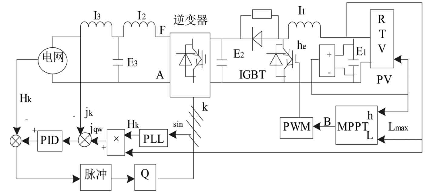
Among them, the main circuit is composed of a solar photovoltaic array PV, LLCL filter, DC/AC solar inverter, DC/DC converter, and corresponding control units of the circuit. In the Boost DC/DC circuit, the highest power point tracking control method is used to control the duty cycle of the switch tube, and the battery terminal voltage e h of the solar photovoltaic cell at the output of the highest power is tracked. qw j ∗ is used as the instantaneous reference current for the operation of the solar inverter in the DC/AC grid connected inverter control, and the peak value of qw j ∗ is the DC current Lmax at the output of the highest power tracking of the solar photovoltaic cell, Phase and frequency are the phases and frequencies of the grid voltage. Therefore, this control method can not only enable the solar grid connected inverter to track the phase and frequency of the power grid, but also timely transmit the highest power to the power grid, completing the tracking of the highest power point; In addition, the concept of grid voltage feedforward control and filtering capacitor current inner loop control is added to enhance the stability of the overall control system. In the past, most of the harmonic components in the output current of solar inverters were attenuated using LCL filters. The drawback of this filter is that when the power of the solar grid connected inverter is high, the switching frequency is low, and the required inductance for using this filter is high. Increasing the inductance value is not conducive to the operation of the solar inverter and will cause cost growth. Therefore, this article selects LLCL type filters for the design of solar grid connected inverters, which can not only reduce the harmonic components in the grid connected current, but also reduce the inductance design.
1.2.2 Control strategy
The highest power conversion voltage during the operation of solar photovoltaic cells is expressed in Hqw, which is set as the output voltage of the front-end DC/DC of the solar inverter, and the solar inverter is set as a GPWM voltage gain converter. Based on this, the solar grid connected inverter and LLCL filter model in Figure 1 can be simplified into the circuit structure diagram shown in Figure 2.
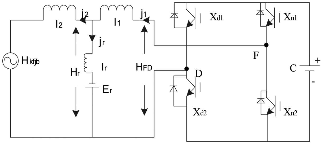
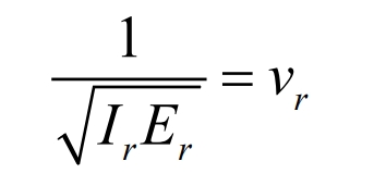
The LLCL filter connects a small inductor in series to the capacitor branch of the previous LCL filter, and together with the capacitor, forms a series resonant circuit. The expression for the series resonant frequency is:
By using Figure 2, the equivalent model of the LLCL filter can be obtained, as shown in Figure 3. The transfer function of the open loop j2 (x)/hFD (x) of the system can be obtained, and its formula is:
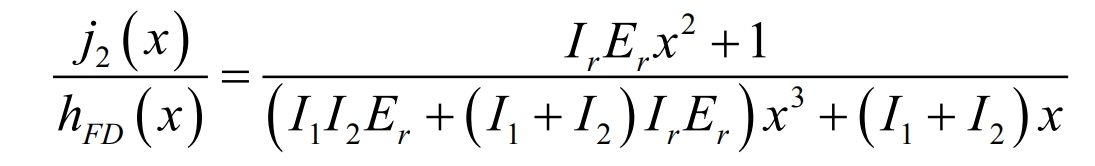
Comparing the open-loop j2 (x)/hFD (x) of the system when using LLCL filter and LCL filter, assuming that the parameters of 1I, 2I, and Er are the same, the attenuation effect of LLCL filter is much higher than that of LCL filter for high-order harmonics at the series resonant frequency position. Therefore, the series resonant frequency can be set at the switch frequency position, which can significantly weaken the high-order harmonics at the grid connected current switch frequency position.
Due to the fact that the defect of resonant peaks still exists in systems using LLCL filters, and their gain is higher than 0 dB, in order to make the system more stable, control of resonant peaks should be provided. The control of LLCL filters can be achieved through active or passive damping of LCL resonance. Here, a dual current closed-loop active damping method with a series resonant circuit current inner loop and a grid side current outer loop is selected, and the feedforward control method of the grid voltage is added to reduce the disturbance caused by grid voltage interference or distortion in the grid connected current. The schematic diagram of feedforward control is shown in Figure 4.
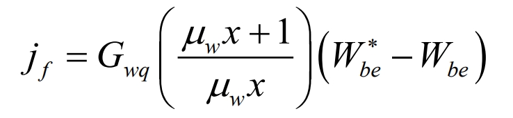
Among them, Lref and Lkfjb respectively represent the given reference current signal and the actual output grid connected current of the solar inverter. The grid side current outer loop regulator and the series resonant circuit current inner loop proportional regulator are represented as Kx and G, respectively. The transfer function of the actual output current of the solar grid connected inverter can be obtained according to Figure 4, which is:
In the formula, there is a direct correlation between the grid connected output current and the reference current, and the interference of grid voltage on the grid connected current can be eliminated through the above feedforward control.
1.3 Network side current outer loop PI control
The control model of the grid side current outer loop with the current inner loop as the control object is shown in Figure 5.
The expression is:
The sampling delay of DC voltage is represented by c ^ – Mwx, and the transfer function of the current loop can be obtained by the formula, which is approximately 1/(Mwx+1)=1 (4Mwx+1), then:
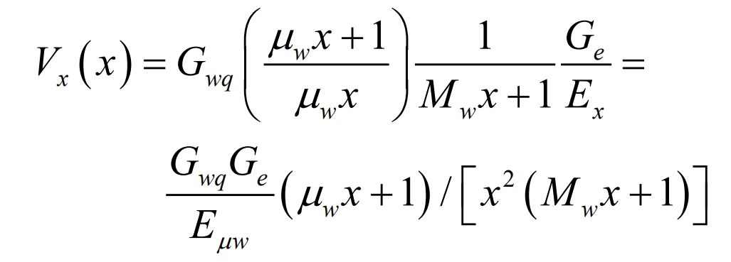
Consider the outer loop control as a second-order system, and its formula is:
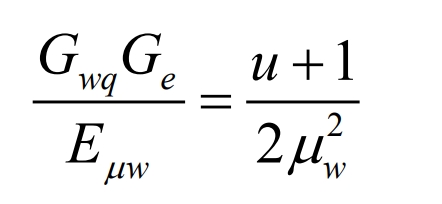
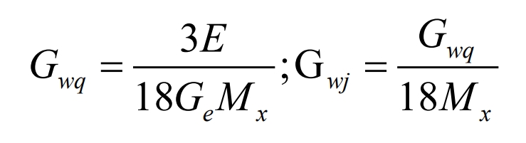
In the equation, let u=µ w/4Mwx=5 µ w=18Mwx, then the parameters of PI are:
2. Analysis of simulation experiment results
By testing the application effect of the new solar unidirectional photovoltaic grid connected system studied by the application institute, the application performance of the inverter in the new solar unidirectional photovoltaic grid connected system can be verified. The experiment used Matlab/Simulink to establish a simulation model of a new solar unidirectional photovoltaic grid connected system. The simulation parameters of the system are shown in Table 1.
2.1 Dynamic performance
Conduct simulation experiments on the solar grid connected inverter studied in this paper, which is used in the experimental new solar unidirectional photovoltaic grid connected system. Observe the changes in grid connected current and grid voltage during the experimental process. The specific changes are shown in Figure 6.
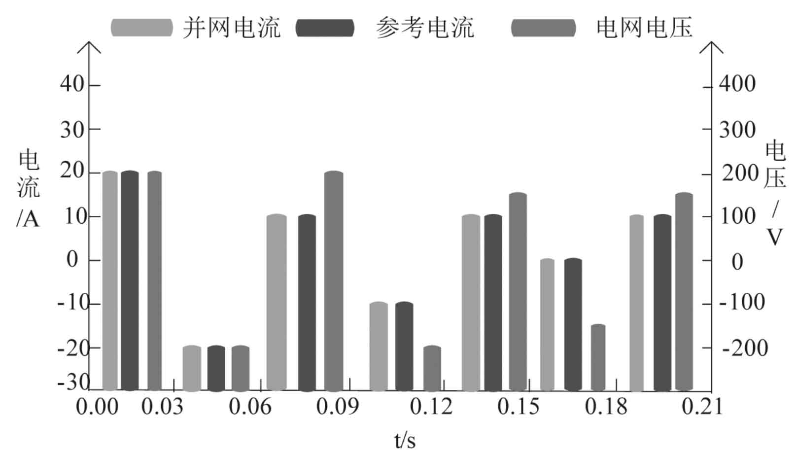
From Figure 6, it can be seen that in the simulation results of solar grid connected inverters, the grid voltage suddenly showed a downward trend at 0.15 seconds, and the grid connected current amplitude decreased by half at 0.09 seconds. The grid connected current can track the reference current in a timely manner and has good resistance to grid voltage interference. This indicates that the new solar unidirectional photovoltaic grid connected system using the studied solar inverter has good dynamic performance.
2.2 Comparison of filtering performance
In the simulation experiment, simulate the number of harmonics present in the power grid voltage, which are 2, 4, 6, 8, and 10 harmonics. Compare the LLCL filter used in the new solar unidirectional photovoltaic grid connected system with the traditional LCL filter, and obtain the comparison results by conducting Fourier analysis of the grid connected current when filtering the two filters. See Figure 7.
| Parameters | Numerical value |
| DC side voltage/V | 380 |
| Filter capacitor/ μF | 4 |
| Inverter side inductance/mH | 3 |
| Switching frequency/Hz | 9K |
| Power grid fundamental frequency/Hz | 40 |
| Network side inductance/mH | 2 |
| Rated grid connected current/A | 28 |
| Resonant inductance/ μH | 50.61 |
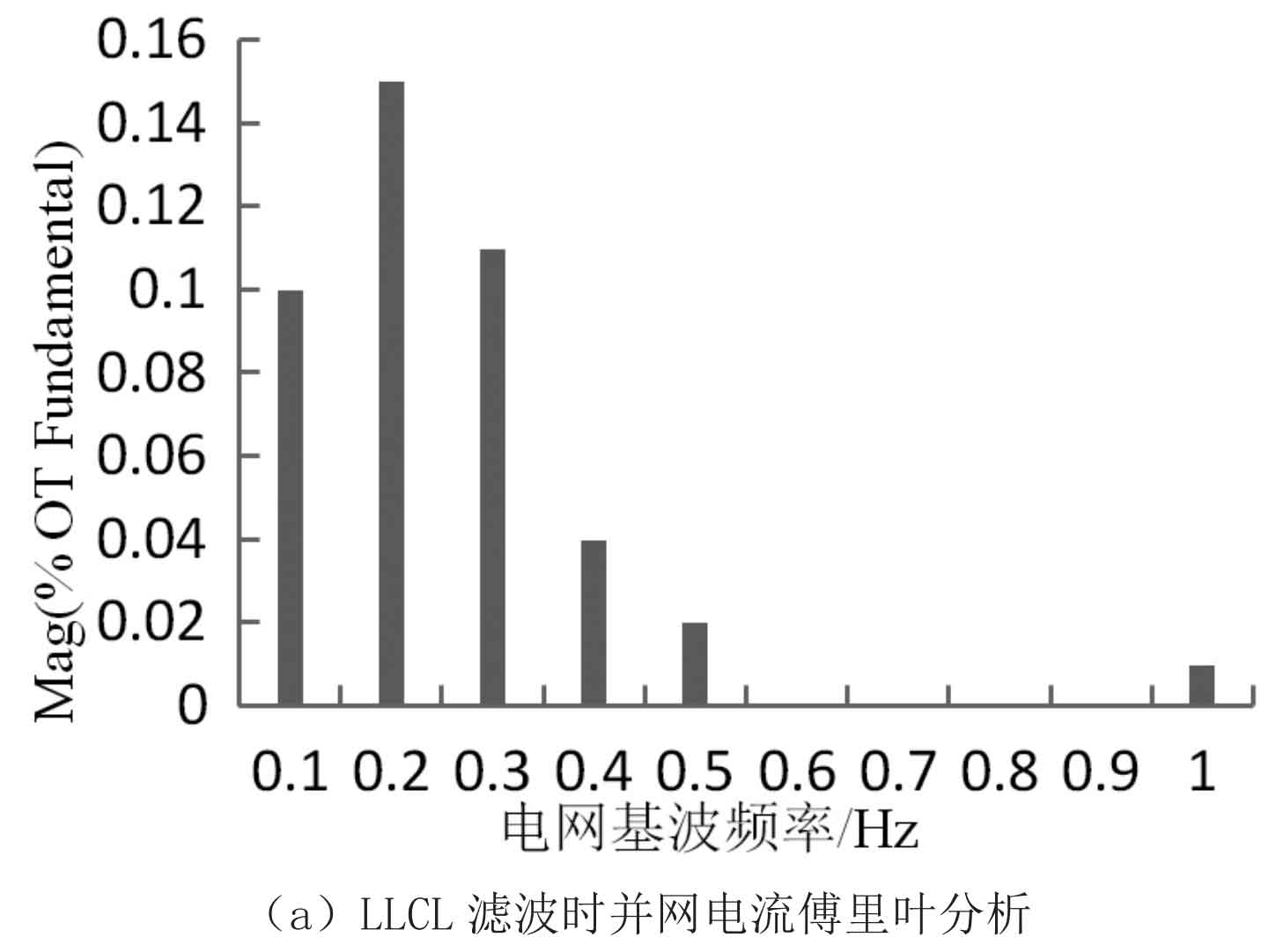
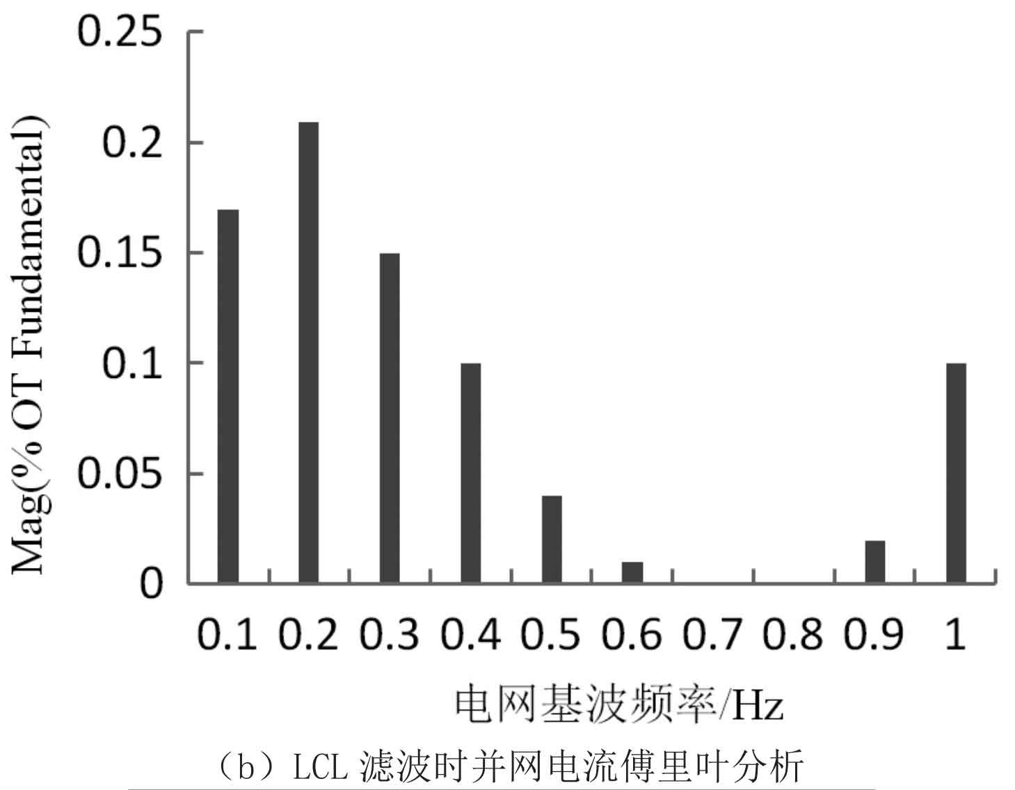
By analyzing Figure 7, it can be concluded that when there are large 2nd, 4th, 6th, 8th, and 10th harmonics in the grid voltage, the traditional LCL filter aggregates a large number of higher-order harmonics of the grid connected current around the switching frequency, and its total harmonic distortion rate (THD) of the grid connected current is 0.55%; The LLCL filter of the new solar unidirectional photovoltaic grid connected system using the studied solar inverter greatly weakens the grid connected current harmonics around the switching frequency, and its THD value is 0.38%, which is lower than the THD value of the LCL filter. This indicates that the LLCL filter performance of the new solar unidirectional photovoltaic grid connected system using the studied solar inverter is superior.
2.3 Application Performance Comparison
Four lighting intensities are set here, in order: 900 W/m ^ 2 for 0-0.1 seconds, 100 W/m ^ 2 for 0.1-0.2 seconds, 700 W/m ^ 2 for 0.2-0.3 seconds, and 200 W/m ^ 2 for 0.3-0.4 seconds. The four lighting intensities are applied to the photovoltaic cells in the new solar unidirectional photovoltaic grid connected system using the studied solar photovoltaic inverter and the photovoltaic cells in the single-phase photovoltaic off grid system, Compare the changes in output current of two systems under different lighting intensities to verify the application performance of the new solar unidirectional photovoltaic grid connected system using the studied solar inverter. The results are shown in Figure 8.
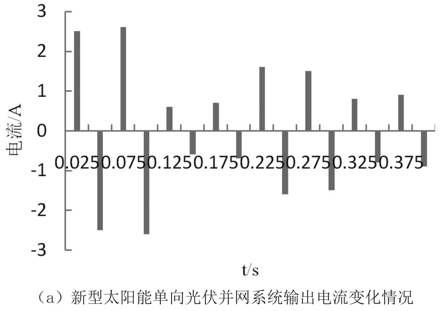
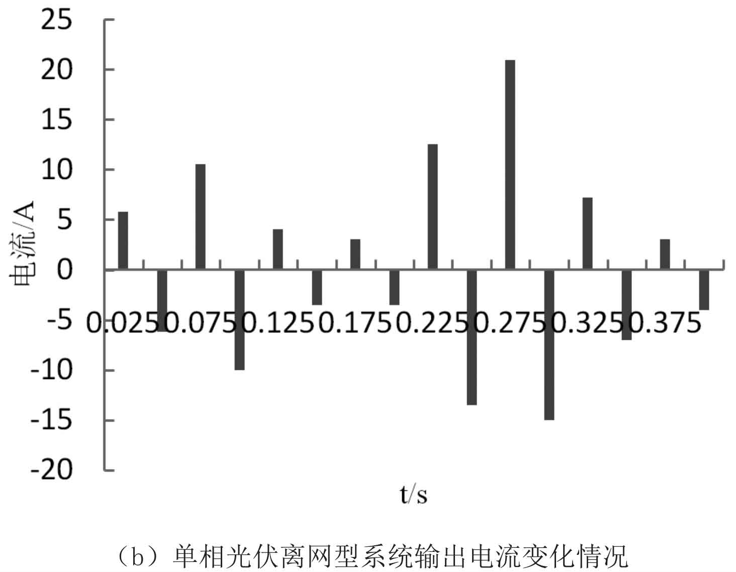
By analyzing Figure 8, it can be concluded that the output current of the new solar unidirectional photovoltaic grid connected system using the studied solar inverter is directly proportional to the intensity of incident light, which can timely track the highest power of the photovoltaic cells in the system and make the output grid connected current more stable. This indicates that the studied solar inverter has improved the operational quality of the new solar unidirectional photovoltaic grid connected system, The application performance of the solar inverter studied is good.
3. Conclusion
This article establishes a new type of solar unidirectional photovoltaic grid connected system, and designs and analyzes the solar grid connected inverter at its core position. The LLCL filter is used in the solar inverter, which can weaken the high order harmonics of the grid connected current at switch frequency positions with more harmonics, improve the quality of the current, and use grid voltage feedforward control to improve the anti-interference performance of the system, Combining the PI control of the external current loop on the grid side to control the internal current loop and improve system stability. The simulation experiments have verified that the stability of the system in this paper is good and the quality of the output current is high, indicating that the new solar single-phase solar inverter in this paper has superior application performance.