
1. The principle of inverters in solar power generation systems
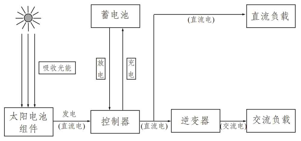
The distributed household solar power generation system is essentially a low-voltage DC system. The 12-48 volts of electricity emitted by the solar photovoltaic cells are connected to the battery, stored in the battery, and then converted into 220 volts of AC electricity through a solar inverter to supply AC loads such as household appliances (as shown in Figure 1).
Traditional solar photovoltaic inverters consist of two parts. The front-end DC-DC DC conversion circuit and the back-end DC-AC inverter circuit are composed. Due to the low output voltage of the photovoltaic array composed of solar photovoltaic cells, usually only 12V, 24V, and 48V DC voltages are used. Therefore, the first step is to convert the low voltage DC energy into higher voltage DC energy, and the subsequent DC-AC solar inverter can output 220V AC power. Therefore, DC-DC circuits mostly use multi branch parallel structures or sampling boost DC conversion circuits; The subsequent DC-AC circuit adopts a PWM inverter circuit to reduce harmonics.
2. Requirements for inverter power supply in photovoltaic power generation systems
Requirements for inverters in solar photovoltaic power generation systems:
(1) Has high efficiency.
(2) Having a reasonable circuit structure to improve its reliability, and having appropriate protective functions to adapt to remote rural areas that are unmanned and maintained.
(3) It can still operate normally and output stable AC voltage even with a large range of DC input voltage changes.
(4) If a distributed household solar power generation system needs to be connected to the grid, the solar inverter is required to output a current close to sine wave to avoid causing power pollution to the public grid.
3. DC-AC solar inverter using Buck Boost transformation principle
Due to the fact that the AC output voltage of traditional voltage source solar inverters (VSIs) is always lower than their DC input voltage, solar photovoltaic grid connected inverters must consist of two parts. The front-end DC-DC DC converter circuit is used to increase the DC voltage, while the back-end DC-AC inverter circuit converts DC power into AC power. The two-stage converter circuit results in a large device weight and volume, reducing conversion efficiency. The Boost AC chopper proposed in this article combines a DC chopper that increases DC voltage with a DC-AC solar inverter. It can achieve the functions of traditional solar photovoltaic inverters by using a single-stage circuit. The main circuit is shown in Figure 3.
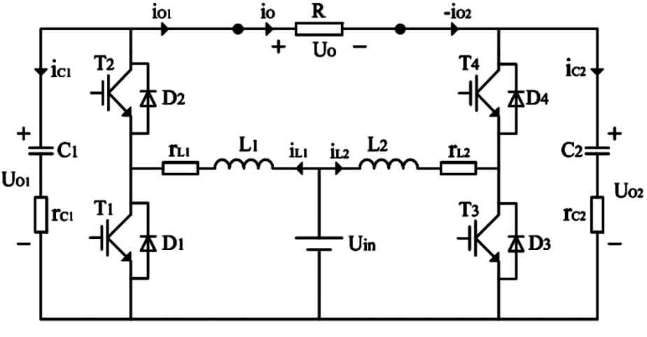
A single-phase Boost DC-AC AC chopper consists of two identical Boost DC-DC converters, with the load connected across the output terminals of the two converters to achieve positive and negative half cycle AC chopping. Taking a Boost DC-DC converter as an example, the working principle is explained below, and its circuit is shown in Figure 4.
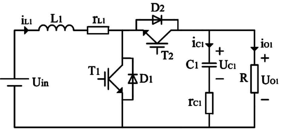
In the figure, Uin is the DC input power supply, rL1 is the equivalent series resistance of inductor L1, rC1 is the equivalent series resistance of capacitor C1, T1 and T2 are two power switches, and capacitors D1 and D2 are freewheeling diodes. Two power switches and freewheeling diodes can achieve bidirectional energy flow. The working principle is that when T1 conducts, T2 turns off, the inductance current iL1 increases linearly, diode D2 cuts off, capacitor C1 provides power to the load, and capacitor voltage UC1 decreases. When T1 is turned off and T2 is closed, the inductor current iL1 provides electricity to the capacitor and load, and capacitor C1 is charged. For the circuit shown in Figure 4, the output input voltage relationship is:
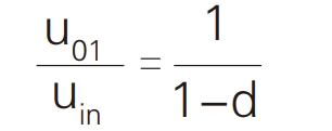
In the formula: U01 is the output voltage of the single-phase DC-DC converter, and d is the duty cycle.
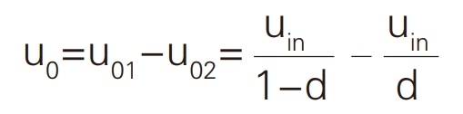
The output voltage is:
The voltage gain is:
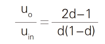
As can be seen from the above equation, the output voltage of the DC-DC converter is related to the duty cycle, so the AC output voltage can be changed by adjusting the duty cycle. In addition, this circuit also has the advantages of fewer switching devices, low switching losses, small harmonic components in PWM modulation, good output waveform, and no need for filtering.
In the circuit shown in Figure 3, due to the reference voltage being set to two sine signals with the same DC bias, the amplitude of the two output sine signals is equal but with a phase difference of 180 °. By superimposing the two output sine signals, the complete sine AC voltage can be obtained on the load.
4. Control Strategy of Boost AC Chopper
Due to the fact that the circuit structure of the Boost AC chopper operates under variable operating point conditions, its control difficulty increases. There are currently two commonly used control methods: sliding mode control and double closed-loop control.
The main advantage of sliding mode control is that it has robustness to model errors and parameter changes in the system, and can achieve good dynamic performance and steady-state response.
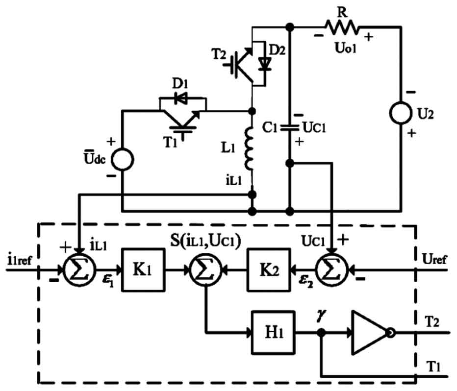
The dashed box in the figure represents the sliding mode controller, which enables the output voltage of the Boost AC chopper to accurately and quickly track changes in the input signal. In Figure 5, the magnitude of coefficients K1 and K2 determines the response speed, stability, and robustness of the system.