
Multilevel solar inverters were proposed in the 1980s, and after the research of many scholars, their related topological structures and applications have been greatly developed. In theory, the more DC side levels there are, the smaller the amplitude of the subsequent stage switch, and the lower the required voltage withstand value of the device. The output waveform of the solar inverter is closer to the modulation wave. As the number of levels increases, the number of components in the inverter circuit also increases significantly, making the modulation strategy more complex and reducing system stability. Therefore, currently the commonly used two-level and three-level solar inverters in photovoltaic power generation systems. The traditional two-level solar inverter has shortcomings such as low system efficiency, high distortion of output voltage waveform, and large filter volume, making it difficult for its inverter system to meet the reliability requirements of high-performance high-power photovoltaic power generation systems. Compared with traditional two-level solar inverters, three-level solar inverters have the following advantages:
(1) The voltage value received by the inverter switching device is greatly reduced, reducing the inverter cost and losses, making it suitable for high-power inverter applications.
(2) The output waveform of a three-level solar inverter is composed of three levels stacked together, resulting in a better output waveform, closer to a sine wave, and lower harmonic content.
(3) Reduced the voltage change rate of the solar inverter filter, improved conversion efficiency, and had better electromagnetic compatibility characteristics.
(4) It can reduce the number of actions of the inverter switch, thereby reducing losses and the heating situation of the solar inverter, and improving the service life and efficiency of the device.
Multilevel solar inverters can be roughly divided into midpoint clamp type, flying capacitor type, and cascaded type according to their structural characteristics.
Mainly provide a brief introduction to the above topology structures.
1. Mid point clamp solar inverter
Neutral Point Clamped (NPC) three-level solar inverter is an improved version of the traditional two-level solar inverter, which adds a capacitor on its DC input side, and the midpoint of the two capacitors serves as the intermediate level. Two diodes are used to clamp the output end at the intermediate level. In addition, add a pair of switching tubes to each phase bridge arm to connect the intermediate level. After the corresponding switch is turned on, three potentials will appear: high potential (P), intermediate potential (O), and low potential (N).
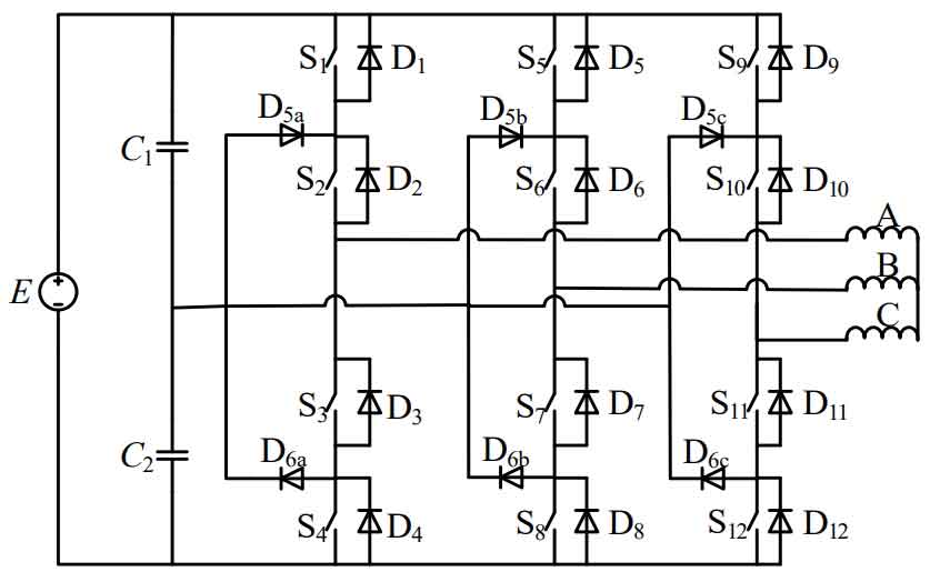
Among them, capacitors C1 and C2 are large capacity capacitors with the same specifications, aimed at stabilizing the DC input side and clamping the midpoint to intermediate level 0. Record the three bridge arms from left to right as three-phase A, B, and C. Taking phase A as an example, record the DC input voltage as E. When switch tubes S1 and S2 are closed and S3 and S4 are disconnected, phase A is connected to a high level. At this time, the output voltage of phase A is E/2, which can be recorded as state P. When switch tubes S2 and S3 are closed and S1 and S4 are disconnected, phase A is connected to the intermediate level. At this time, the output voltage of phase A is 0, which can be recorded as state O. When switch tubes S3 and S4 are closed and S1 and S2 are disconnected, phase A is connected to a low level. At this time, the output voltage of phase A is – E/2, which can be recorded as state N. The A-phase voltage and switch status are shown in Table 1:
| VAO | S1 | S2 | S3 | S4 |
| E/2 | 1 | 1 | 0 | 0 |
| 0 | 0 | 1 | 1 | 0 |
| -E/2 | 0 | 0 | 1 | 1 |
From the above working process, it can be seen that compared with traditional two-level solar inverters, the voltage value received by NPC type solar inverters before and after switching is half of that of two-level solar inverters. Therefore, when using the same specification of switching tubes, three-level solar inverters will double the output power of the inverter. The robustness and cost-effectiveness of the inverter system will be improved, especially in high-voltage and high-power working environments. NPC type three-level solar inverters have great advantages and application value.
A three-level solar inverter has an additional zero level, i.e. the O state, compared to a two-level solar inverter. So as to avoid the switch jumping directly from high level to low level, it is equivalent to quantifying the amplitude of the modulation signal, making the output waveform closer to a sine wave and reducing the impact of harmonics. And due to the decrease in voltage change rate per unit time, magnetic losses are reduced, thereby improving conversion efficiency and overall EMC performance of solar inverters.
While three-level solar inverters have many advantages, they also have their own shortcomings. Due to the different switching time points and the need to charge and discharge the three-phase bridge arms at three times the frequency at the midpoint, there may be errors in the capacity of the two capacitors due to manufacturing processes, which can easily cause significant fluctuations in the midpoint potential. Therefore, an additional midpoint balance control strategy is usually required.
A discontinuous pulse modulation (DPWM) based on NPC type solar inverters is proposed to minimize switching losses under full power conditions. By injecting an appropriate offset signal into the discontinuous reference signal, the midpoint current can be effectively compensated and the phenomenon of capacitor voltage imbalance can be alleviated. A new modulation strategy based on zero sequence voltage injection into the capacitor midpoint (CB-PWM) of NPC solar inverters is proposed by injecting zero sequence voltage signals into the modulation signal. This strategy can reduce low-frequency oscillation of the midpoint voltage and reduce switching losses. Provide a method to replace the P or N switch state in a short period of time with another switch state that does not affect the midpoint voltage. By using an O-state switch to balance the midpoint voltage, this method has strong balancing ability in many cases.
There are still many academic achievements in the research of Space Vector Modulation (SVPWM) strategy for NPC three-level solar inverters: proposing a comprehensive consideration of solar inverter switch losses and output current harmonics, expanding the traditional switch sequence set, and accurately dividing each action area to establish the optimal action area. A comprehensive performance optimization SPWM strategy is proposed. Researching a space vector alternating switching sequence that only applies one axis vector during the synthesis of reference vectors, compared to the traditional method of synthesizing reference vectors using three nearest vectors, it can effectively reduce THD. A simplified SVPWM algorithm is proposed, which utilizes sector rotation and vector mapping methods based on the rotational symmetry characteristics of large sectors to avoid repeated operations of the same algorithm in different large sectors. This can effectively improve computation speed and simplify sector determination steps. Provide a fast SVPWM algorithm that can avoid multiple square root and triangle operations in coordinate transformation, and achieve precise modulation through simple arithmetic operations, greatly simplifying the structure of the SVPWM algorithm and improving its execution speed.
The research on NPC three-level solar inverters is still ongoing, and both hardware circuits and control strategies are gradually being optimized. This will promote the development of NPC solar inverters towards higher output waveform quality, more stable performance, and lower design costs.
2. Flying capacitor solar inverter
The flying capacitor solar inverter was proposed in 1992, and its circuit topology is shown in Figure 2:
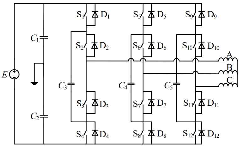
Compared with NPC type solar inverters, the flying capacitor type three-phase solar inverter replaces the clamping diode with a clamping capacitor, while still retaining the DC input measured voltage divider capacitor. The midpoint of the two capacitors is still the zero potential reference point. Its topology structure is similar to the NPC type solar inverter structure, but the working process is slightly different from the NPC type working process. When A is in the P state, switches S1 and S2 conduct, and switches S3 and S4 are in the off state. At this time, the current flows from the high-level bus through switches S1 and S2 to the load, and the phase voltage of A is E/2. When A is in the O state, there are two situations: in the first situation, switches S1 and S3 are in a conducting state, switches S2 and S4 are in a off state, and current flows from the high-level bus through switch S1, capacitor C3, and switch S3 into phase A. At this time, the capacitor is in a charging state; In the second case, switches S2 and S4 are in a conductive state, switches S1 and S3 are turned off, and current flows out of phase A through switch S2, capacitor C3, and switch S4 into the low-level bus. At this time, capacitor C3 discharges towards the load. When A is in state N, switches S3 and S4 are in conductive state, and switches S1 and S2 are in off state. At this time, current flows out of phase A, passes through switches S3 and S4, and flows into the low-level bus terminal. At this time, the voltage of phase A is – E/2. The switch states corresponding to the output voltage of phase A are shown in Table 2:
| VAO | S1 | S2 | S3 | S4 |
| E/2 | 1 | 1 | 0 | 0 |
| 0+ | 1 | 0 | 1 | 0 |
| 0- | 0 | 1 | 0 | 1 |
| -E/2 | 0 | 0 | 1 | 1 |
According to the analysis of the working process of phase A, when the A-phase bridge arm switch is in P and N states, the current does not pass through the capacitor, but directly flows out into the load through the upper and lower bridge arms. Only when the switch state of the A-phase bridge arm is O, its flying capacitor will appear in working state, and the voltage of the flying capacitor needs to be maintained at E/2 for the circuit to operate normally.
Due to the large number of flying capacitors attached to the circuit, it still has the ability to pass through low voltage in the event of power failure, and the output voltage waveform quality is high. The switch state is more flexible and can be combined with switch redundancy to match different levels, making it more suitable for AC transmission scenarios. This structure can be easily extended to a five level structure, but when there are many levels, a large amount of additional energy storage capacitors need to be added, and the control strategy is relatively complex. At the same time, it is also necessary to introduce a control flying capacitor potential balance strategy. When the power factor is high, the switching loss is relatively large.
A digital control method for capacitor voltage balance is proposed to address the issue of voltage deviation in flying capacitors. By judging the direction of imbalance between load current and capacitor voltage, hysteresis control method is adopted to adjust the action time of redundant vectors and achieve stable control of flying capacitor voltage. Point out the use of proportional natural pulse width modulation to select the appropriate switching state, ensuring a balanced distribution of DC voltage and effectively alleviating the problem of capacitor voltage imbalance.
Due to the limited level of industrial manufacturing technology, most of the large capacity capacitors used in industry are electrolytic capacitors, which not only have a relatively large volume but also have a certain service life, making it difficult for subsequent maintenance and repair. Therefore, the application of flying capacitor multilevel solar inverters is limited, making them only suitable for certain specific occasions. With the advancement of capacitor production technology, flying capacitor multilevel solar inverters will be widely studied and applied due to their unique advantages.
3. Cascaded solar inverter
The cascaded multilevel solar inverter is based on the output of multiple independent inverter units stacked in series.
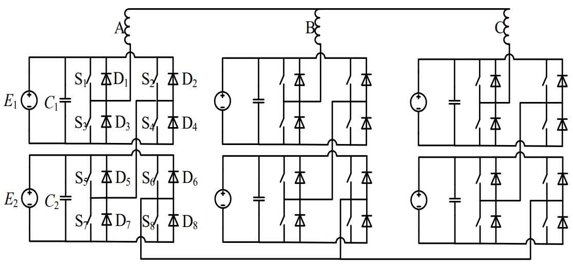
Each phase of the bridge arm is powered by different independent DC power sources to form a full bridge inverter. Multiple solar inverters are connected in series to obtain the corresponding voltage. The switch state corresponding to the output voltage of phase A is shown in Table 3:
| VA0 | S1 | S2 | S3 | S4 | S5 | S6 | S7 | S8 |
| 2E | 1 | 0 | 0 | 1 | 1 | 0 | 0 | 1 |
| E | 0 | 0 | 1 | 1 | 1 | 0 | 0 | 1 |
| E | 1 | 0 | 0 | 1 | 1 | 1 | 0 | 0 |
| 0 | 0 | 0 | 1 | 1 | 0 | 0 | 1 | 1 |
| 0 | 1 | 1 | 0 | 0 | 1 | 1 | 0 | 0 |
| -E | 0 | 0 | 1 | 1 | 0 | 1 | 1 | 0 |
| -E | 0 | 1 | 1 | 0 | 1 | 1 | 0 | 0 |
| -2E | 0 | 1 | 1 | 0 | 0 | 1 | 1 | 0 |
According to the definition of a multi-level solar inverter, n is the number of output levels, and m is the number of DC power sources. Therefore, the number of output levels for different DC power sources in series is n=2m+1. Each unit has an independent power supply and an inverter full bridge, which overcomes the problem of easy fluctuations in busbars and intermediate potentials, and can be easily combined to obtain any level. When it operates in active power conversion situations, it requires a large amount of DC power supply, and its input transformer generally adopts phase shifting mode, which is difficult to design. When converting reactive power, it is also necessary to have a large capacity of bus voltage stabilizing capacitors to avoid large surges in the bus voltage, and it is difficult to operate within the fourth quadrant.
At present, many scholars are still studying cascaded solar inverters, reducing harmonic components through phase-shifting methods, and proposing a new SVPWM modulation method suitable for cascaded multi-level solar inverters. The modulation method is more simple and can effectively eliminate low order harmonics and their sideband harmonics. A method based on improving carrier layer modulation is proposed, which adopts different modulation methods for high and low voltage H-bridges, and performs logical operations on the modulation signals obtained from mixed frequency signals. This can effectively solve the problem of current backflow and improve the output power allocation of high and low voltage H-bridges.
4. Summary
Introduce the working principles and characteristics of three typical multi-level solar inverters, and summarize their advantages and disadvantages. In response to their respective shortcomings, search for relevant literature to understand the research status of different topology structures, laying the foundation for the theoretical analysis of the new three-level solar energy inverter proposed in the following text.