
In response to the national call for “dual carbon”, renewable energy has developed rapidly in recent years, significantly weakening the inertia support capacity of the power grid. In addition, the random fluctuation of renewable energy output also poses a huge challenge to power grid frequency regulation. When traditional conventional units participate in frequency regulation, they will generate additional mechanical losses and carbon emissions, and the frequency response time delay is long, making it difficult to perform the frequency regulation task of the new power system. The development of energy storage provides technical support for this, and its fast response ability can effectively alleviate the frequency regulation pressure brought by renewable energy grid connection. However, currently there are many types of energy storage with different prices and output characteristics. Therefore, selecting appropriate battery types and integrated control methods to reduce life loss during frequency regulation and improve economy has become a research hotspot.
Currently, scholars have conducted research in this field. Decompose the secondary frequency modulation ACE signal of the power grid, with energy storage bearing high-frequency power and conventional units bearing low-frequency power; Propose an adaptive frequency modulation control strategy that takes into account the state of charge (SOC) of battery energy storage, and introduce fuzzy control and regression function to adaptively adjust the battery energy storage output; Analyzed the frequency regulation dead zone of conventional units, and in order to fully utilize the precise and fast response characteristics of energy storage, the frequency regulation dead zone of energy storage was set within the dead zone of conventional units to constrain their output; A real-time output increment prediction model for conventional thermal power units was constructed, and a thermal power flywheel energy storage collaborative frequency modulation control strategy was proposed to achieve adaptive adjustment of flywheel energy storage under different load disturbance conditions, optimizing energy storage and conventional unit output; However, the above studies have all improved the battery life by reducing its energy storage output, which cannot balance the frequency modulation effect. For battery energy storage, the main factors affecting its lifespan include the number of cycles and the depth of discharge (DOD). In order to reduce the impact of frequent charging and discharging switching on battery life, the dual battery energy storage mode has emerged. Research has been conducted in scenarios such as voltage stability in distribution networks and suppressing wind power fluctuations. The results show that this mode can reduce the equivalent number of battery energy storage cycles. However, there is little research on the dual battery energy storage mode in frequency modulation scenarios. In addition, considering the wide variety of battery energy storage types and significant differences in cost and operating characteristics, selecting appropriate battery types in frequency modulation scenarios can improve economic efficiency.
In summary, current research has optimized the energy storage output to improve its lifespan, and cannot balance the frequency modulation effect. Moreover, the characteristics and economy of multiple types of batteries vary, and it is necessary to combine the characteristics of frequency modulation scenarios and battery energy storage control modes to determine suitable battery types to improve economy. In this regard, this article proposes an integrated control strategy for dual battery energy storage in the scenario of secondary frequency regulation in the power grid, and analyzes and evaluates the energy storage economy of multiple types of batteries. Firstly, a battery energy storage conventional unit participation power grid secondary frequency regulation model based on ACE control was established, fully leveraging the fast response characteristics of energy storage frequency. Then, the battery energy storage system is divided into two parts with different charging and discharging characteristics for integrated control. The frequency modulation power is independently tracked to extend the service life, and the life curve of multiple types of batteries is fitted based on experimental data. A battery energy storage life evaluation model and a life cycle cost model based on the rain flow counting method are constructed to evaluate the economy of frequency modulation for multiple types of battery energy storage. Finally, the effectiveness of the proposed strategy was verified based on actual load disturbance data and the energy storage economy of multiple types of batteries was analyzed.
1. Battery Energy Storage – Conventional Unit Secondary Frequency Modulation Model
1.1 Equivalent Frequency Modulation Model for Conventional Thermal Power Units
This article adopts thermal power units with relatively small external influence and large capacity for frequency regulation. When participating in grid frequency regulation, it is necessary to comprehensively consider the constraints of delay coefficient, slope rate, power, and capacity. The frequency deviation signal generated by the system is converted into the active output of conventional units by the governor and steam turbine. The transfer function of the equivalent frequency regulation model is expressed as:
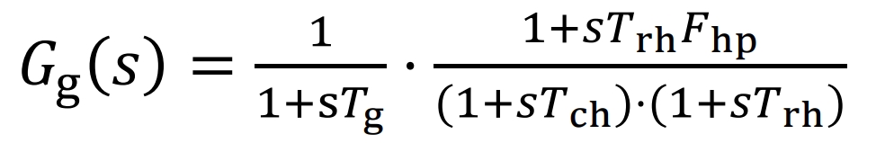
In the formula: Tg is the governor time constant Trh, Thp, and Tch are the reheater time constant, reheater gain, and turbine time constant, respectively.
1.2 Equivalent Frequency Modulation Model for Battery Energy Storage
The speed and accuracy of battery energy storage in response to frequency changes in the power grid are fast and high. When participating in frequency modulation, a first-order inertial link is usually used for equivalence, and its transfer function is expressed as:
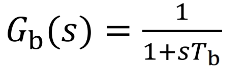
In the formula, Tb is the battery energy storage time constant.
In order to reflect the frequency regulation margin of battery energy storage at any time, the state of charge (SOC) is introduced for characterization. Taking time k as an example, it is represented as
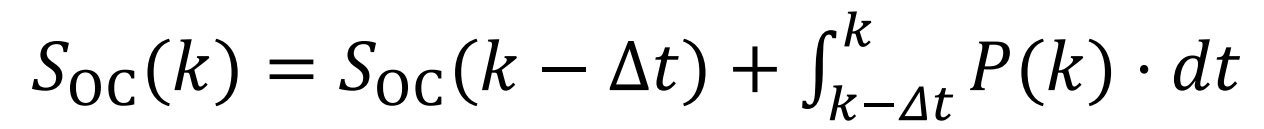
In the equation, Δ T is a power instruction sampling cycle; P (k) is the power command for battery energy storage at time k; SOC (k) is the k-th sampling point.
1.3 Battery Energy Storage Assisted Secondary Frequency Modulation Model for Conventional Thermal Power Units
When participating in the secondary frequency regulation of the power grid, this article adopts the automatic generation control (AGC) mode. Based on the participation of thermal power units in the primary frequency regulation of the power grid, the unbalanced power signal Ace (s) generated by the system is jointly borne by the battery energy storage and thermal power frequency regulation units, and is distributed according to certain principles. The control model is as follows.
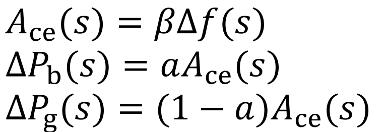
In the equation: β Is the frequency deviation coefficient; Δ F (s) is the system frequency deviation; Δ Pg (s) is the ACE signal undertaken by the thermal power frequency modulation unit; Δ Pb (s) is the ACE signal borne by the battery energy storage; A is the ACE distribution coefficient for battery energy storage, and 1-a is the ACE distribution coefficient for thermal power units, determined based on the battery energy storage and conventional unit frequency regulation capacity.
When there is a frequency deviation in the system, in order to make the battery energy storage respond quickly to the ACE signal, this article only uses PI control for thermal power units to participate in the primary and secondary frequency regulation of the power grid. The battery energy storage only participates in the secondary frequency regulation, and the response power Pg (s) and Pb (s) of thermal power units and battery energy storage are represented as:
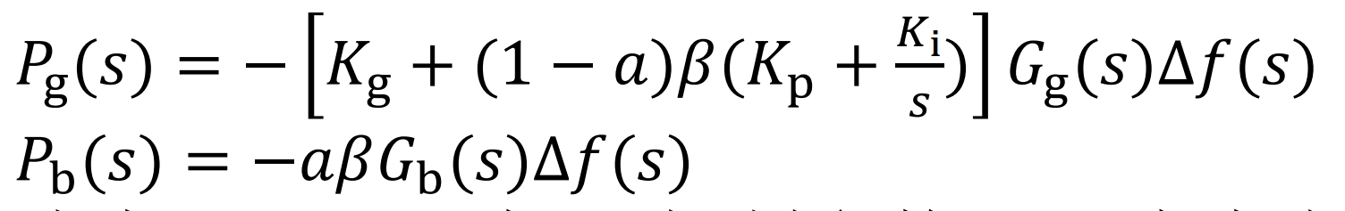
In the formula, Kp and Ki are PI control parameters; Kg is the unit power regulation coefficient of primary frequency regulation for thermal power units.
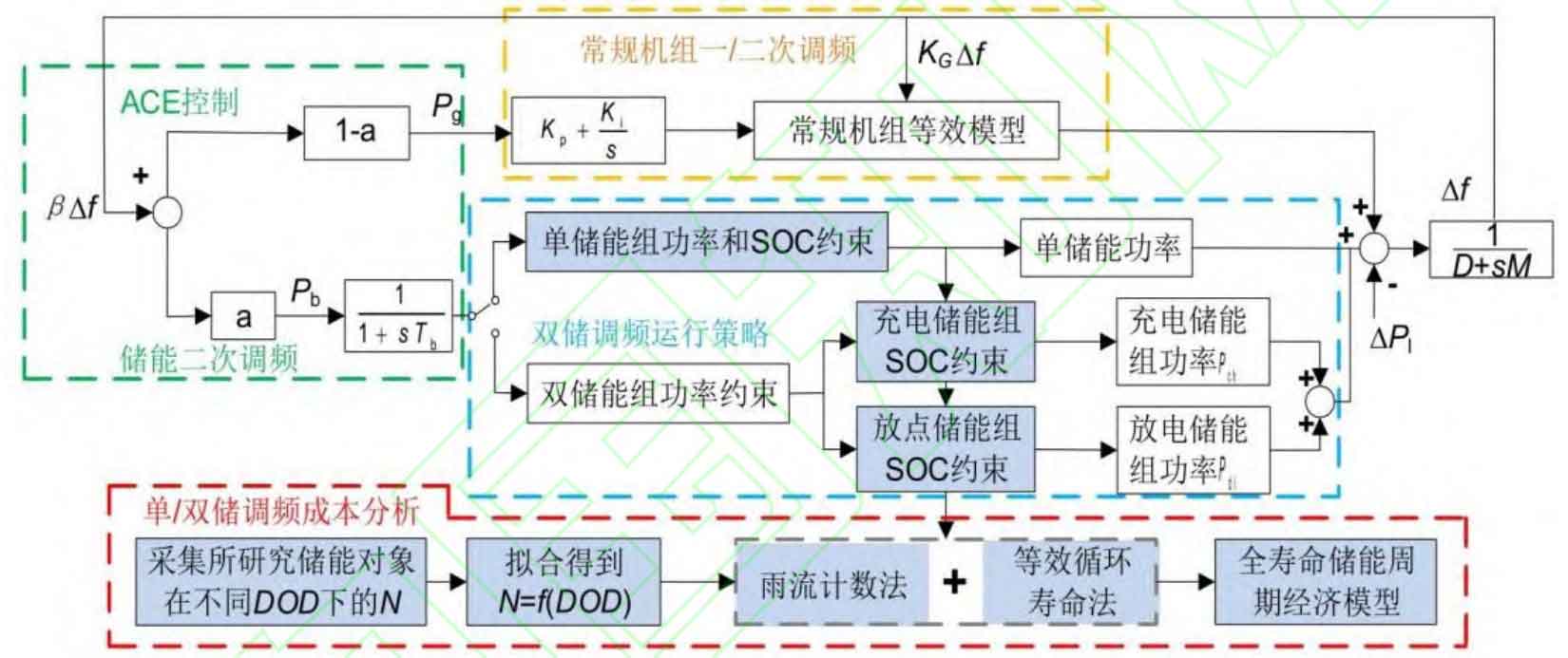
According to the load disturbance Pl of the power grid, the response power Pg of the thermal power frequency regulation unit, and the response power Pb of the battery energy storage, the real-time frequency deviation of the power grid can be obtained as shown in equation (9). Substituting equation (7) and equation (8) can obtain equation (10) . The frequency modulation block diagram of the regional power grid is shown in Figure 1.
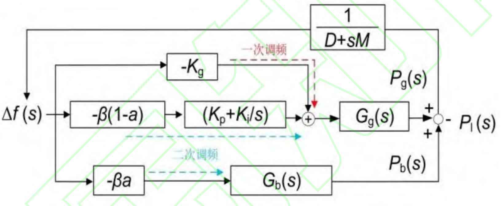
In the formula, D and M are the load damping coefficient and the rotational inertia of the thermal power unit, respectively.
2. Integrated control strategy for battery energy storage for secondary frequency regulation of power grid
Load disturbances usually have randomness, causing frequency fluctuations above and below the reference frequency. When battery energy storage participates in frequency regulation, frequent charging and discharging switching is required, thereby increasing its equivalent cycle count and having a significant impact on lifespan. Therefore, in order to reduce this impact, a dual battery energy storage integrated control strategy for secondary frequency modulation is proposed. The battery energy storage system is divided into two parts with different charging and discharging characteristics, and each part independently undertakes the charging and discharging frequency modulation task. When the SOC of a certain battery energy storage group reaches the set limit, the charging and discharging modes of the two battery energy storage groups are switched. The specific process is as follows.
Step 1: Determine the SOC range for battery energy storage operation. Based on the test data provided by the manufacturer and the energy storage life decay method, the optimal life extension effect can be obtained in this mode. This article states that the optimal discharge depth is DOD, and the SOC boundary for battery energy storage operation can be expressed as:
𝑆OCmax = (1 + 𝐷OD)/2
𝑆OCmin = (1 − 𝐷OD)/2
In the formula, SOCmax is the upper limit of battery energy storage operation SOC, and SOCmin is the lower limit of battery energy storage operation SOC.
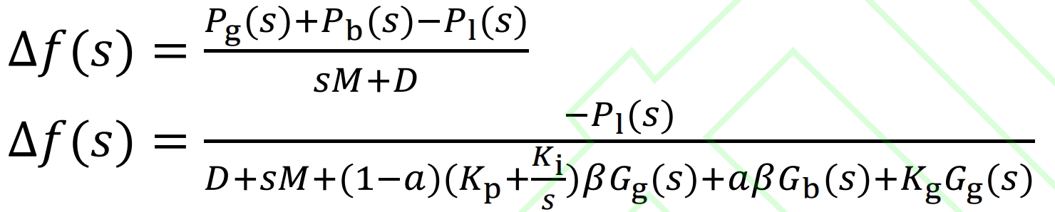
Step 2: Determine the energy storage tracking power of the charging and discharging battery. When Pb (s) determined by equation (8)>0, it is executed by the discharge energy storage group, and the charging energy storage group is standby; On the contrary, when Pb (s)<0, it is executed by the charging energy storage group and the discharging energy storage group is standby. In addition, considering the rated power and SOC constraints of the battery energy storage group, taking k time as an example, the power of the charging/discharging battery energy storage group can be expressed as:
In the formula, Pch (k) and Pdi (k) are the battery energy storage, charging, and discharge power at time k; Pbn is the rated power of the battery energy storage system, and Sbn is the rated capacity of the battery energy storage system. Due to independent tracking of power commands during operation, the charging and discharging power and capacity of both battery energy storage groups are half of those of the battery energy storage system; η Improve the efficiency of the battery energy storage group.
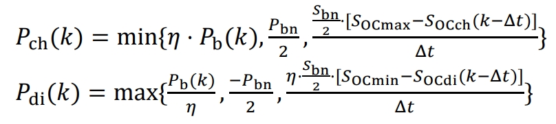
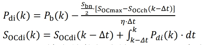
Step 3: Switching the charging and discharging states of the two battery energy storage groups. When the SOC of the charging energy storage group reaches SOCmax or the SOC of the discharging energy storage group reaches SOCmin, the charging and discharging states of the two battery energy storage groups are switched to enter the next charging and discharging cycle. And when the charging/discharging energy storage group cannot complete this power command due to rated power or SOC constraints, the remaining part will be compensated by the discharging/charging energy storage group, as follows.
1) The charging energy storage group has reached SOCmax and has not completed the charging power command. At this time, the compensation power and SOC update of the discharging energy storage group are represented as:
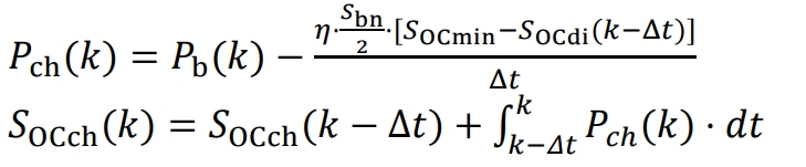
2) The discharge energy storage group reaches SOCmin first and has not completed this discharge power command. At this time, the compensation power and SOC update of the charging energy storage group are represented as:
3. Calculation of Energy Storage Life and Economic Evaluation Model for Multiple Types of Batteries
In order to evaluate the economy of applying dual battery integrated mode in the secondary frequency modulation scenario of multiple types of battery energy storage, a life assessment model and a full life cycle cost model were established for each type of battery energy storage characteristic.
3.1 Assessment Model for Energy Storage Life of Multiple Types of Batteries
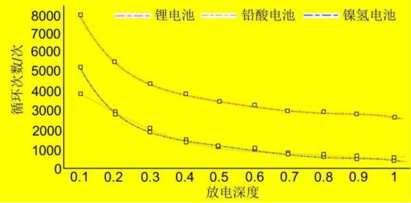
For battery energy storage, discharge depth and number of cycles are the main factors affecting the operating life, and the number of cycles is a function of DOD
| Battery discharge depth | Lithium battery | Lead-acid battery | Nickel hydrogen battery |
| 0.1 | 8000 | 3800 | 5200 |
| 0.2 | 5600 | 2850 | 2800 |
| 0.3 | 4500 | 2050 | 1830 |
| 0.4 | 4000 | 1300 | 1450 |
| 0.5 | 3600 | 1050 | 1010 |
| 0.6 | 3400 | 900 | 850 |
| 0.7 | 3150 | 750 | 680 |
| 0.8 | 3100 | 650 | 500 |
| 0.9 | 3000 | 600 | 420 |
| 1 | 2800 | 550 | 350 |
Department. According to the relationship between DOD and cycle number N obtained from engineering tests of multiple types of battery energy storage (lithium batteries, lead-acid batteries, nickel hydrogen batteries), as shown in Table 1, a fifth order polynomial is used for fitting. The DOD-N function relationship is shown in equation (19), and the fitted polynomial coefficients and curves are shown in Table 2 and Figure 2.

| Battery polynomial coefficient | Lithium battery | Lead-acid battery | Nickel hydrogen battery |
| a | -220.2 | 119 | -213.3 |
| b | 287.1 | -27.54 | 358.9 |
| c | 58.43 | -535.8 | 72.6 |
| d | 224.3 | 629.3 | 16.05 |
| e | -804.6 | -488 | -750.2 |
| f | 3500 | 923.2 | 978.3 |
Due to the real-time variation of DOD during the secondary frequency regulation process of battery energy storage, in order to unify with the test data form and effectively compare to obtain the actual operating life, the rain flow counting method is first used to calculate the number of cycles under different DODs, and the equivalent cycle life method and DOD-N relationship curve are used to convert the number of cycles under different DODs to the number of cycles under DOD=1 and sum it up. Then, the number of cycles under DOD=1 is compared with the number of test cycles under DOD=1, The actual operating life Tnb of the battery energy storage obtained is:
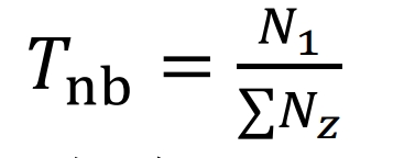
In the formula, N1 is the number of cycles under DOD=1; Nz is the number of cycles converted under different DODs.
Power type pool energy storage, such as supercapacitors, flywheel energy storage, and superconducting magnetic energy storage, is less affected by DOD. The main influencing factor on their lifespan is the number of charges and discharges, and the cost of power type energy storage is high. Therefore, it is not suitable to adopt a dual energy storage operation mode. Therefore, in subsequent comparisons, only a single power type energy storage will be considered. Based on its actual daily charging and discharging times, its service life is estimated. Assuming that it operates for t days per year, its actual operating life Tgb is:
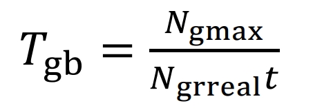
In the formula, Ngmax is the maximum number of charges and discharges during the life cycle of power type energy storage; Ngreal is the actual number of charges and discharges per day for power type energy storage.
3.2 Economic Evaluation Model for Battery Energy Storage Based on Full Life Cycle Cost
The full life cycle cost model refers to the total amount of expenses incurred throughout the entire life cycle of an energy storage system, including investment costs, replacement costs, auxiliary equipment costs, operation and maintenance costs, scrap disposal costs, and residual value recovery. This article uses the cost present value method, assuming that the total service life of battery energy storage is T years and the benchmark discount rate is I. The specific content of the model includes a battery energy storage capacity configuration model and a battery energy storage full life cycle cost evaluation model.
3.2.1 Battery Energy Storage Capacity Configuration Model
The principle of battery energy storage power configuration is to meet the maximum power command demand during the operating cycle, expressed as, where k0 is the starting time; Ki and kj are the maximum and minimum power moments during the operating cycle, respectively. The principle of battery energy storage capacity configuration is to avoid overcharging and discharging during the operating cycle, which can be calculated based on the cumulative energy curve of battery energy storage, expressed as:
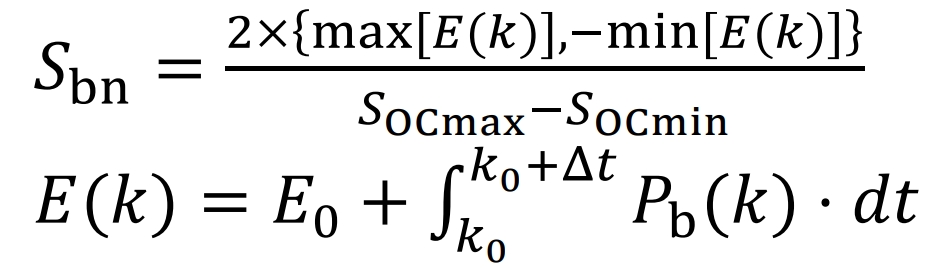
In the formula, 𝐸 0 is the initial energy storage of the battery; 𝐸 (𝑘) is the accumulated energy stored by the battery at any time.
3.2.2 Life cycle cost assessment model
(1) Energy storage investment cost
𝐶 binv=𝐶 bpinv 𝑃 bn+𝐶 bsinv 𝑆 bn
In the formula, Cbpinv is the investment cost per unit power of energy storage; Cbsinv is the investment cost per unit capacity of energy storage.
(2) Energy storage replacement cost
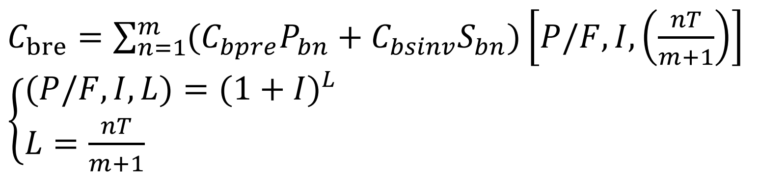
In the formula, Cbpre is the replacement cost per unit power of energy storage; M is the number of energy storage replacements within T years; (P/F, I, L) is the one-time payment cash coefficient.
(3) Auxiliary equipment cost
𝐶 bbop=𝐶 bpbop •𝑃 bn+𝐶 sbop •𝑆 bn
In the formula, Cbpbop is the auxiliary cost per unit power of energy storage; Csbop is the auxiliary cost per unit capacity of energy storage.
(4) Battery energy storage operation and maintenance costs
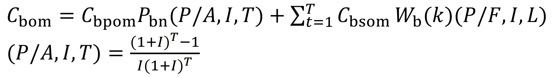
In the formula, Cbpom is the unit power operation and maintenance cost of energy storage; Cbsom is the operation and maintenance cost per unit of energy storage; Wb (k) is the annual charging and discharging capacity of energy storage; (P/A, I, T) is the present value coefficient of equal distribution.
(5) Scrap processing cost
𝐶 bscr=(𝐶 bpscr 𝑃 bn+𝐶 bsscr 𝑆 bn) (𝑚+1) (𝑃/𝐹, 𝐼, 𝐿)
In the formula, Cbpscr is the cost of scrapping per unit power of energy storage; Cbsscr is the cost of scrapping per unit capacity of energy storage.
(6) Recycling residual value;
𝐶 bres=𝛾 bres (𝐶 binv+𝐶 brep+𝐶 bbop) (𝑃/𝐹, 𝐼, 𝐿)
In the equation, γ Bres is the residual value rate of energy storage recovery.
In summary, the total cost generated during the life cycle of the energy storage system is shown in equation (33).
𝐶 tot=𝐶 binv+𝐶 brep+𝐶 bbop+𝐶 bom+𝐶 bscr − 𝐶 bres
The energy storage system proposed in this article participates in the full life cycle cost evaluation process of secondary frequency regulation, as shown in Figure 3.
4.Simulation analysis
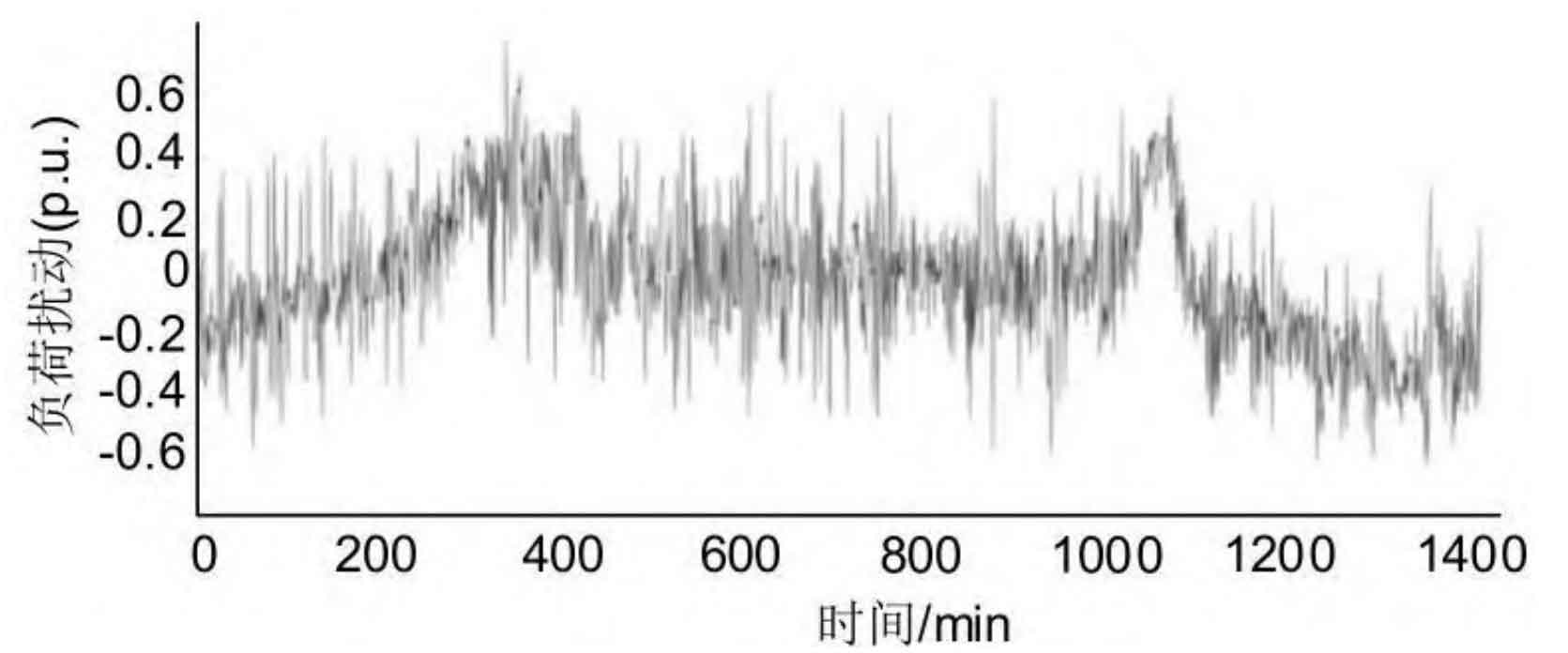
Based on the simulation analysis of the regional power grid secondary frequency regulation model in Figure 3, the conventional unit frequency regulation reserve capacity is 40 MW, and the battery energy storage system capacity configuration is 40 MW/30 MWh, that is, when the dual battery integrated control is used, both batteries are 20 MW/15 MWh. DOD is set to 0.8, SOC initial value is 0.5, and other parameters are standardized based on 100 MW as shown in Table 3. The study focuses on the 24-hour continuous load disturbance data of a regional power grid, with a sampling interval of 1 minute. The load disturbance curve is shown in Figure 4.
| Parameters | Value | Parameters | Value |
| M | 5 | D | 1 |
| B | 20 | KG | 21 |
| Tg | 0.08 | Kp | -0.822 |
| Tb | 0.01 | Ki | -0.16 |
| TCH、TRH | 0.3、10 | FHP | 0.5 |
| I | 0.1 | γbres | 0.04 |
| T | 10 | η | 0.95 |
4.1 Simulation analysis of energy storage assisted conventional frequency regulation units participating in secondary frequency regulation of the power grid
Firstly, verify the benefits of energy storage participating in power grid frequency regulation. The frequency changes of the power grid, energy storage output, and single energy storage SOC curves are shown in Figures 5-7.
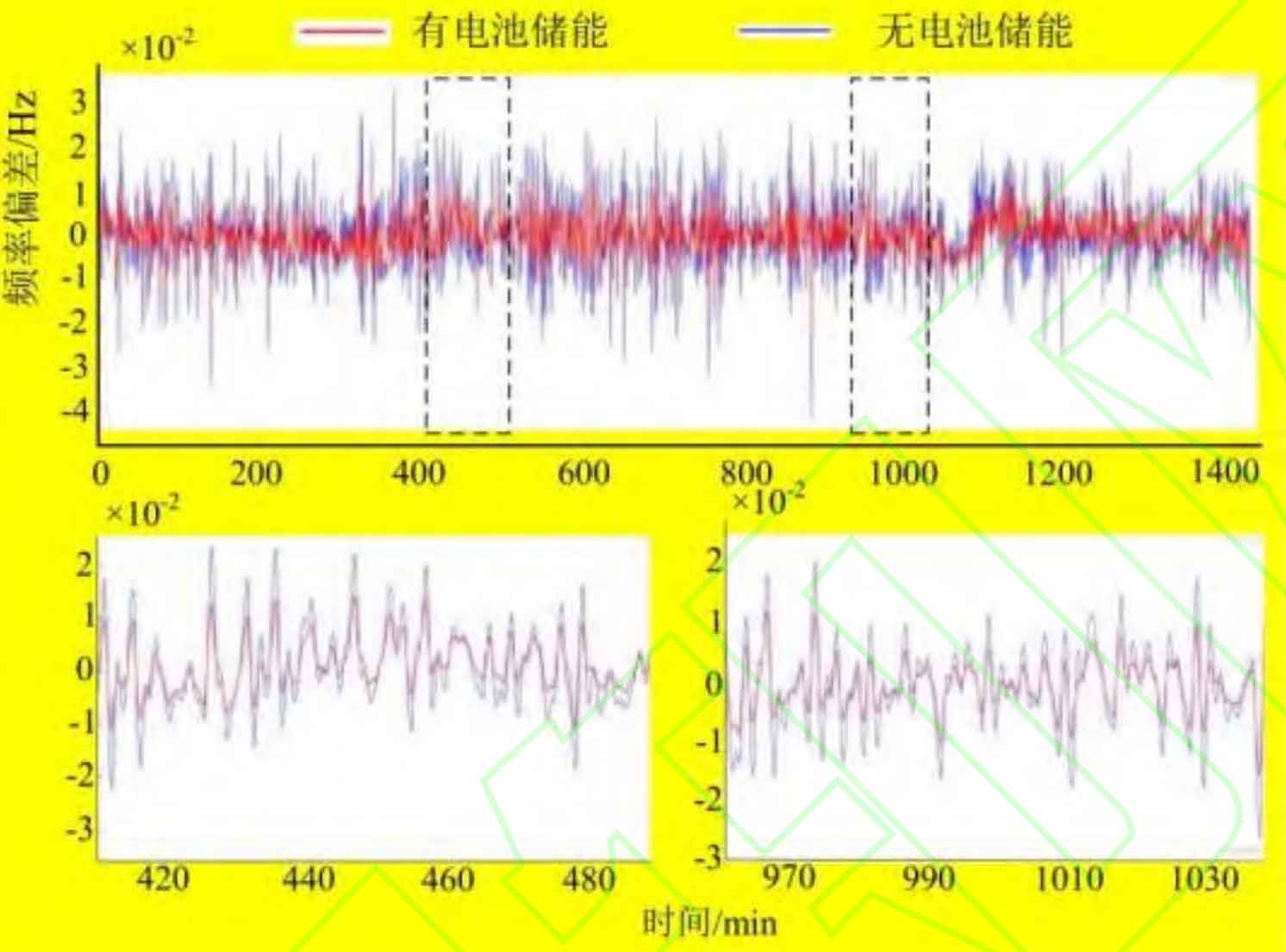
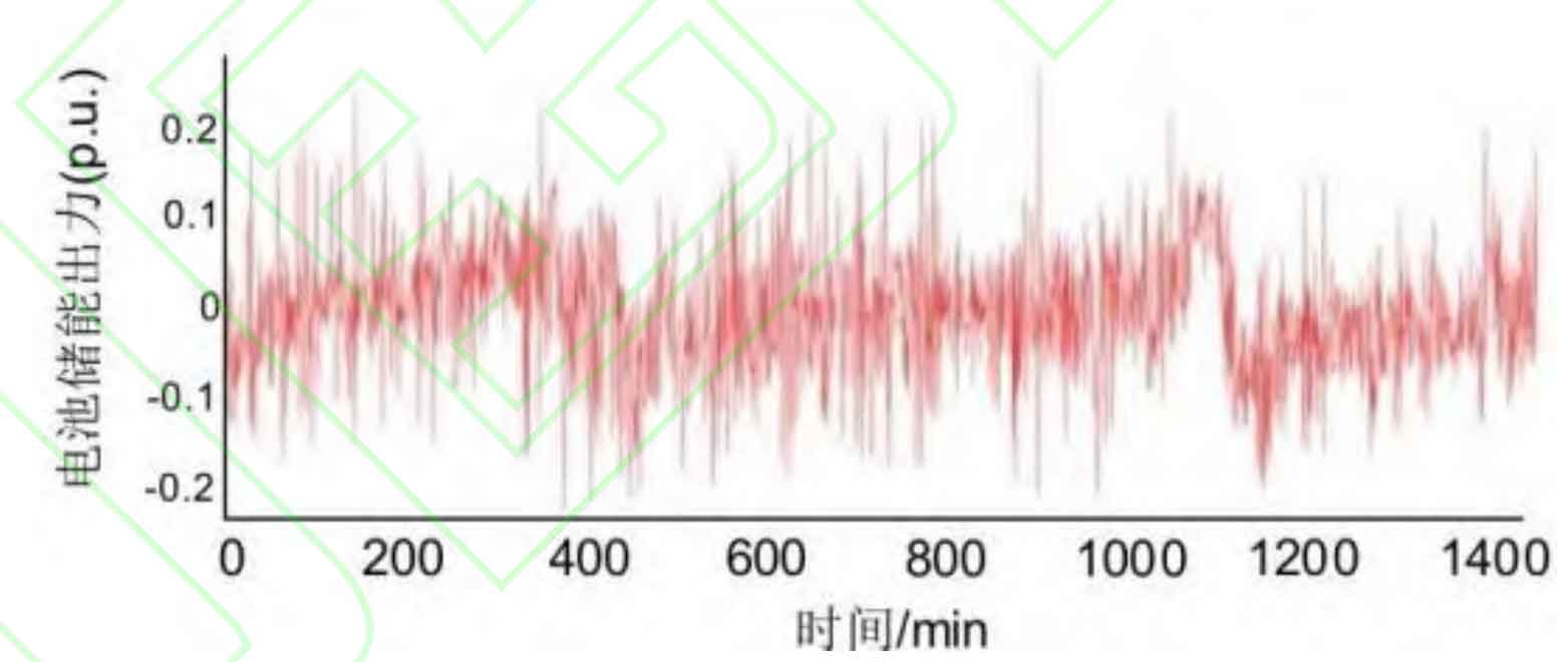
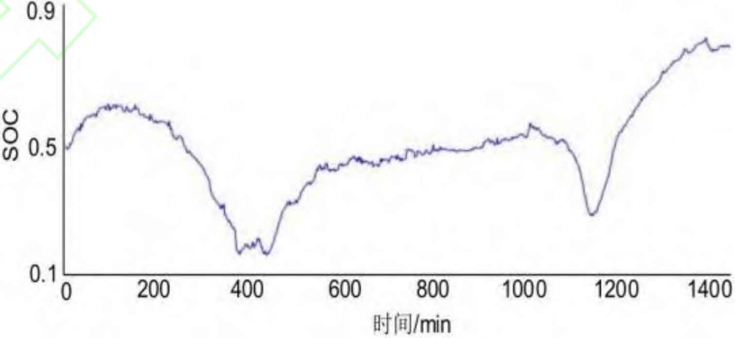
Figure 5 shows the frequency changes of the power grid when there is no energy storage and when there is energy storage participating in frequency regulation. Analysis shows that the frequency modulation effect is better when energy storage is involved in frequency modulation than when there is no energy storage. The reason is that compared to conventional thermal power frequency modulation units, energy storage has a faster frequency change response ability and can quickly suppress frequency fluctuations.
| Frequency modulation effect indicators | No energy storage | With energy storage |
| Maximum forward frequency deviation/Hz | 0.0337 | 0.0182 |
| Minimum reverse deviation/Hz | -0.0422 | -0.0224 |
| Average absolute value of frequency deviation/Hz | 0.0071 | 0.0041 |
Figure 6 and Figure 7 show the SOC for energy storage frequency modulation power and single energy storage tracking power commands. When configured using the capacity configuration model presented in this article, energy storage can track frequency modulation commands to compensate for system imbalance power and meet SOC operational constraints. From a data perspective, as shown in Table 4, the maximum forward frequency deviation and minimum reverse frequency deviation of energy storage participating in grid frequency regulation are 0.0182 Hz and -0.0224 Hz, respectively. The average absolute value of frequency deviation is 0.0041 Hz. Compared to battery free energy storage, the frequency regulation indicators have increased by 45.97%, 46.93%, and 42.35%, respectively.
4.2 Simulation Analysis of Dual Battery Energy Storage Integrated Control Strategy
According to the analysis in Section 2, for battery energy storage, dual battery integrated control can reduce the impact of frequent charging and discharging on battery life. This article adopts dual battery integrated control to track frequency modulation power commands for three common types of battery energy storage (lithium battery, lead-acid battery, nickel hydrogen battery), and compares and analyzes the frequency modulation economy with three types of power type energy storage (supercapacitor, flywheel energy storage, superconducting magnetic energy storage). The dual battery energy storage output, SOC curve, and charge discharge state switching symbols are shown in Figures 8 to 10. The equivalent number of cycles and cycle life calculated based on the life assessment model are shown in Tables 5 and 6.
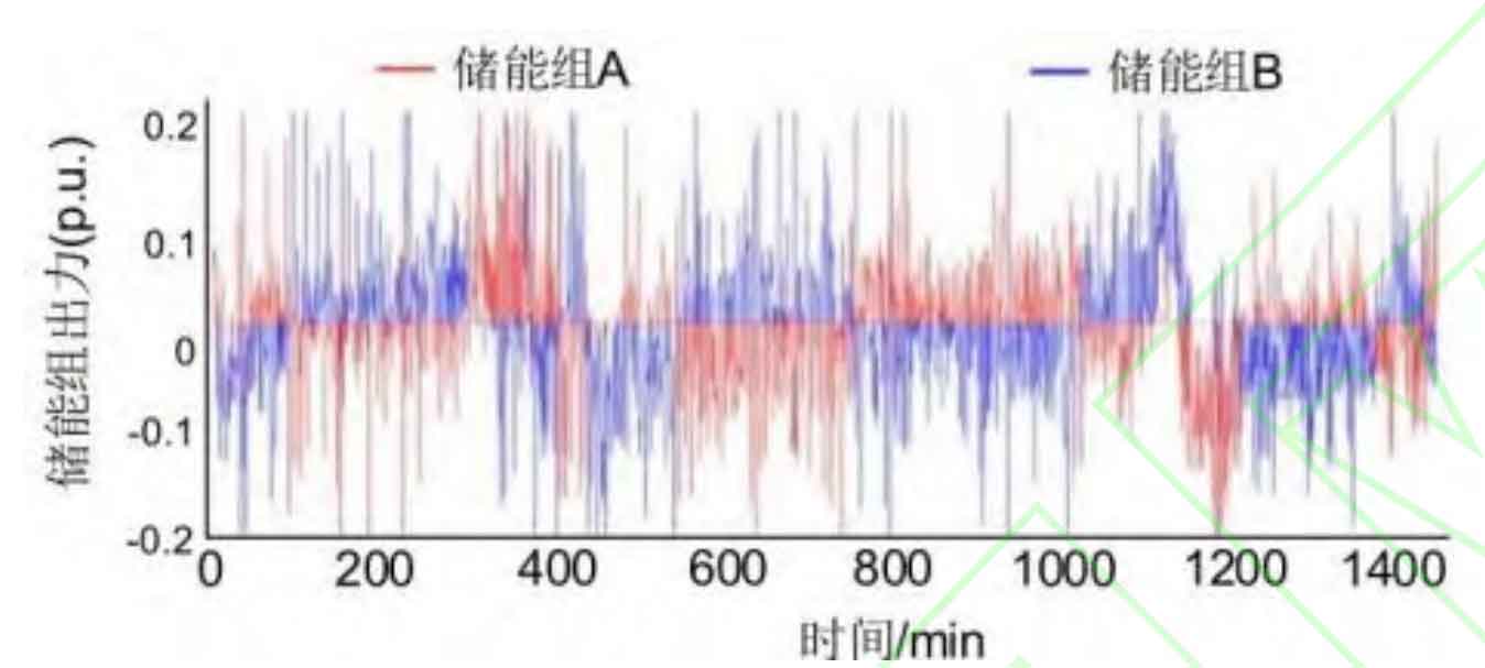
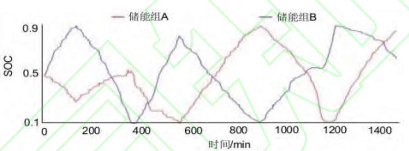
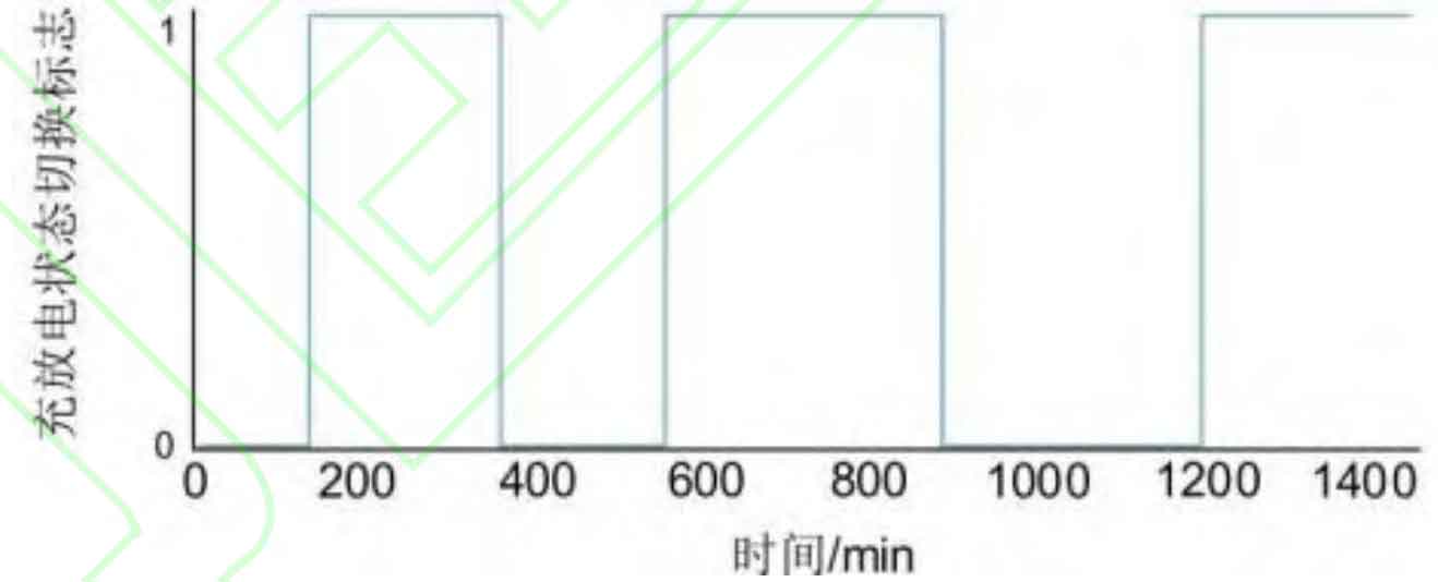
From Figures 8-10, it can be seen that when A battery’s energy storage discharge compensates for negative load disturbance, B battery’s energy storage charging compensates for positive load disturbance. When A/B battery’s energy storage reaches the SOC boundary, A battery’s energy storage switches to charging mode, and B battery’s energy storage switches to discharge mode, avoiding frequent charging and discharging switching, and meeting the power constraints and available charging and discharging capacity constraints of each group of batteries. At the same time, the switching of charging and discharging states between two battery packs can enable the battery to operate close to the optimal DOD (such as 0 min-300 minutes, 600 min-1200 minutes, etc.), thereby fully utilizing its cycle life and extending the battery’s service life.
| Battery type | Lithium battery energy storage A | Lithium battery energy storage B | Lithium battery single energy storage control | Lead acid battery energy storage A | Lead acid battery energy storage B | Single energy storage control of lead-acid batteries | Nickel hydrogen battery energy storage A | Nickel hydrogen battery energy storage B | Single energy storage control of nickel hydrogen batteries |
| Equivalent number of cycles/time | 3.362 | 3.337 | 14.318 | 1.770 | 1.518 | 8.278 | 1.687 | 1.4136 | 2.071 |
| Average number of cycles/time | 3.350 | 3.350 | 14.318 | 1.644 | 1.644 | 8.278 | 1.550 | 1.550 | 2.071 |
| Daily charging and discharging capacity/kWh | 67.255 | 61.011 | 128.266 | 67.255 | 61.011 | 128.266 | 67.255 | 61.011 | 128.266 |
From the perspective of data analysis, as shown in Tables 5 and 6, when using the dual battery integrated control mode, the equivalent cycles of energy storage for the three types of batteries were all smaller than those for single battery control. The equivalent cycles of lithium batteries, lead-acid batteries, and nickel hydrogen batteries were reduced by 76.6%, 80.1%, and 25.1%, respectively; The equivalent service life has been extended by 4.27 times, 5.06 times, and 1.35 times respectively, and in the dual battery integrated control mode, the average service life of lithium batteries is significantly better than that of lead-acid batteries and nickel hydrogen batteries, at 846.4 days.
| Equivalent battery life | Lithium battery | Lead-acid battery | Nickel hydrogen battery |
| Single energy storage/day | 198.0 | 49.8 | 165.1 |
| Energy storage group A/day | 843.3 | 232.7 | 202.7 |
| Energy storage group B/day | 849.5 | 271.5 | 241.9 |
| Average service life of dual energy storage/day | 846.4 | 252.1 | 222.3 |
4.3 Economic Evaluation of Multi type Energy Storage Frequency Modulation Based on Dual Battery Integrated Control
| Battery type | Supercapacitor | Flywheel energy storage | Superconducting magnetic energy storage |
| Daily charging and discharging capacity/kWh | 128.266 | 128.266 | 128.266 |
| Equivalent service life/day | 1091.4 | 682.1 | 1364.3 |
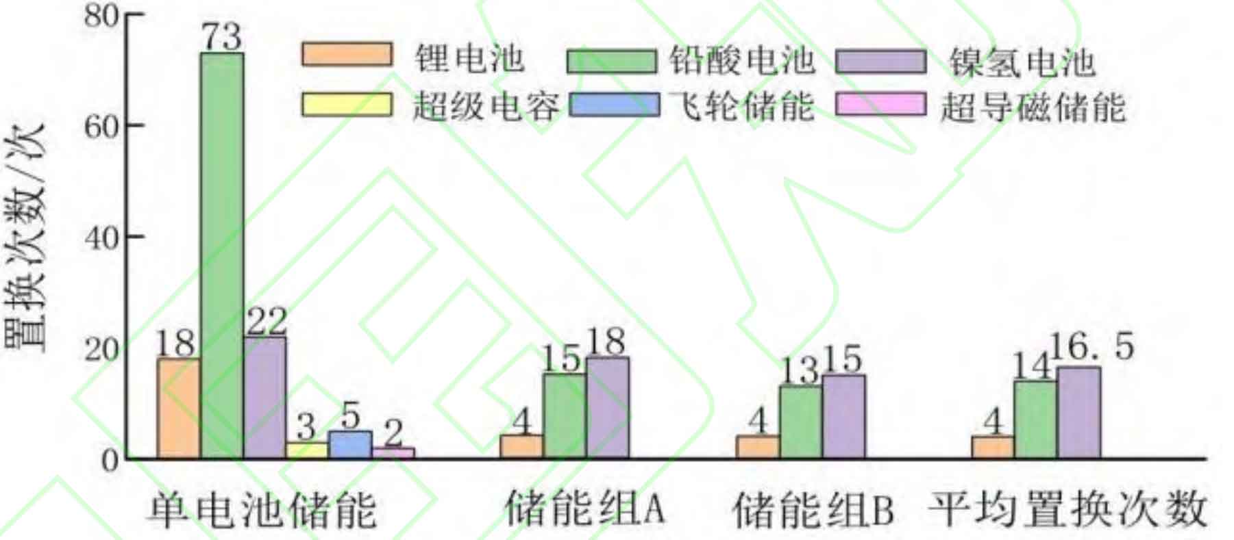
Firstly, calculate the operating life of power type energy storage according to equation (21), as shown in Table 7. In order to reduce the cost error caused by rounding up the replacement frequency and form an effective comparison, this article takes a 10 year life cycle. The calculated number of replacement times for multiple types of energy storage is shown in Figure 11. Analysis shows that power type energy storage has a longer lifespan and requires less replacement times than battery energy storage. Compared to single battery control, using dual battery integrated control can significantly reduce the number of battery energy storage replacements.
From an economic perspective, the economic parameters of various types of energy storage are shown in Table 8. Based on the full life cycle cost model of energy storage in Section 3.2, the frequency modulation costs of lithium batteries, lead-acid batteries, and nickel hydrogen batteries under single battery control and dual battery integrated control, as well as supercapacitors, flywheel energy storage, and superconducting magnetic energy storage under single battery control can be obtained, as shown in Table 9.
| Battery type | Lithium ion batteries | Lead-acid battery | Nickel hydrogen battery | Supercapacitor | Flywheel energy storage | Superconducting magnetic energy storage |
| Cpinv/[yuan/(kW)] | 9300 | 2790 | 1860 1 | 860 | 2170 | 1860 |
| Ceinv/[yuan/(kW · h)] | 9300 | 1860 | 3500 12 | 400 | 31000 | 62000 |
| Cprep/[yuan/(kW)] | 2472.3 | 1152.4 | 1200 1 | 860 | 1011.7 | 1860 |
| Cerep/[yuan/(kW · h)] | 9 300 | 1860 | 3500 12 | 400 | 31000 | 62 000 |
| Cpbop/[yuan/(kW)] | 620 | 620 | 620 | 620 | 620 | 620 0 |
| Cebop/[yuan/(kW · h)] | 0 | 0 | 0 | 0 | 0 | 9300 |
| Cpom/[yuan/(kW · a)] | 62 | 62 | 93 | 80.6 | 111.6 | 62 |
| Ceom/[yuan/(kW · h)] | 0.01407 | 0.002479 | 0.01407 | 0.0134 | 0.0134 | 0.0134 |
| Cpscr/[yuan/(kW)] | 465 | 139.5 | 93 | 93 | 108.5 | 93 |
| Cescr/[yuan/(kW · h)] | 0 360 | 0 | 0 | 0 | 0 | 0 |
From Table 9, it can be seen that the frequency modulation cost of each type of battery under dual battery integrated control is lower than that under single battery control. The reason for this is that the initial investment cost of dual battery power and capacity is the same as that of single battery. However, under dual battery integrated control, the replacement frequency of each type of battery is significantly reduced, resulting in a decrease in replacement cost and scrap cost under full life cycle cost assessment. Due to the varying energy storage costs of various types of batteries, the sum of life cycle frequency modulation costs for lithium batteries, lead-acid batteries, and nickel hydrogen batteries under dual battery integrated control is 8.088, respectively × 108 yuan, 3.727 yuan × 108 yuan and 7.170 yuan × 108 yuan, reduced by 48.1%, 70.3%, and 19.2% respectively compared to a single battery, and its frequency modulation cost is better than that of power type energy storage. In addition, in the dual battery integrated control mode, using lead-acid batteries has the best frequency regulation economy, with a cost of 3.727 × 10 ^ 8 yuan.
| Energy based energy storage cost | Lithium battery | Lead-acid battery | Nickel hydrogen battery |
| Energy storage group A/yuan | 4.044×10^8 | 1.937×10^8 | 3.817×10^8 |
| Energy storage group B/yuan | 4.044×10^8 | 1.789×10^8 | 3.352×10^8 |
| Dual energy storage cost and/yuan | 8.088×10^8 | 3.727×10^8 | 7.170×10^8 |
| Single energy storage/yuan | 1.558×10^9 | 1.255×10^9 | 8.878×10^8 |
| Power type energy storage | Supercapacitor | Flywheel energy storage | Superconducting magnetic energy storage |
| Cost/yuan | 9.741×10^8 | 1.258×10^9 | 2.531×10^9 |
5. Conclusion
A dual battery energy storage integrated control strategy is proposed for the scenario of energy storage participating in secondary frequency regulation of the power grid, and a life cycle cost model is constructed to evaluate the economy and adaptability of multiple types of battery energy storage frequency regulation. Through example analysis, the following conclusions can be drawn:
(1) The proposed dual battery energy storage integrated control strategy enables the battery to operate at the optimal discharge depth, effectively reducing battery life loss and significantly extending its service life. Compared to single battery control, the service life of lithium batteries, lead-acid batteries, and nickel hydrogen batteries has been extended several times, respectively.
(2) The establishment of a full life cycle cost model for energy storage has effectively compared the adaptability of multiple types of energy storage frequency modulation from an economic perspective. When using single energy storage frequency modulation, the cost of super capacitor frequency modulation is the lowest, and its frequency modulation economy is the best. When using dual battery integrated control, compared to single battery control, lithium batteries, lead-acid batteries, and nickel hydrogen batteries have significantly reduced costs throughout their entire life cycle, and lead-acid batteries have the lowest frequency regulation cost and the best frequency regulation economy.