
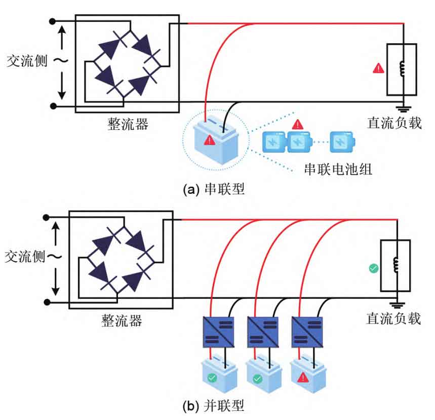
The backup power supply can ensure the normal operation of core equipment in case of system failure. Compared to valve controlled sealed lead-acid batteries, lithium-ion batteries (hereinafter referred to as “lithium batteries”) are widely used in power DC power systems due to their advantages such as high energy density, no memory, low self discharge rate, and green environmental protection. The traditional technical solution for backup power supply is to connect multiple batteries in series into a group and then merge them into the DC bus, as shown in Figure 1 (a). The most obvious drawback of this technical solution is that if a single battery is damaged, the backup system will directly malfunction. For high-voltage faults, if backup operating power cannot be provided, it will cause the circuit breaker at this level to be unable to open, and even directly trip the superior power grid. In addition, due to the general voltage of battery cells being around 4 V, in order to meet the high voltage requirements of DC systems, dozens or even hundreds of cells need to be connected in series. The more batteries connected in series, the more complex the balance between individual cells becomes. Therefore, in response to the shortcomings of the traditional technical solutions mentioned above, a parallel backup power supply scheme has emerged, which first connects batteries in series and then modules in parallel. The parallel scheme is shown in Figure 1 (b). That is, first connect batteries with relatively consistent performance in series into groups, and then equip each series battery group with independent DC-DC converters in parallel to supply power to the load. Replacing the traditional series mode of backup power supply with this parallel module not only avoids the wooden barrel effect caused by a single battery failure that makes the entire series battery pack unusable, but also allows parallel modules to serve as backup for each other, significantly improving the reliability and energy utilization rate of backup power supply.
There may be slight differences in the internal resistance, self discharge rate, and other characteristics of batteries. Specifically, series battery packs may exhibit inconsistent voltage distribution among individual cells. If not balanced in a timely manner, it may cause specific battery cells to overcharge, discharge, or even explode. Parallel battery packs, on the other hand, directly exhibit inconsistent current distribution, which leads to differences in battery energy distribution and capacity attenuation. The different capacity attenuation of parallel battery modules can lead to some modules reaching their end of life earlier, disrupting the backup relationship between multiple parallel modules, reducing the overall reliability of the system, and requiring additional manpower to inspect, increasing the maintenance cost of the system. Therefore, it is necessary to balance the life of the parallel type scheme of series first and then parallel, so that the characteristics of each battery cell are as close as possible.
There are many studies on the balancing methods of series battery packs, mainly divided into two categories: passive balancing and active balancing. Passive balancing mainly relies on energy consuming components (such as resistors) to consume excess energy from high-energy battery cells in the battery pack, ensuring that the energy of the battery pack remains consistent. The passive balancing method generates a large amount of thermal energy during the balancing process. If the heat dissipation is not handled properly, it can easily lead to thermal runaway of the battery system, and passive balancing cannot maximize the utilization of the energy of the battery pack. Active balancing is divided into bypass balancing and energy transfer based balancing. The balance based on energy transfer mainly involves constructing additional energy transmission channels through energy storage components such as capacitors, inductors, and transformers, and designing corresponding management strategies to transfer excess energy from higher energy monomers to lower energy monomers. The equilibrium based on energy transfer is mainly divided into four types: cell to cell (C2C), cell to pack (C2P), pack to cell (P2C), and cell to pack to cell (C2P2C). Compared to passive equalization, energy transfer based equalization methods have advantages such as high energy utilization rate, fast equalization speed, and good battery pack consistency. However, this method also has problems such as large topological volume, high cost, and complex control algorithms. The bypass balancing method mainly utilizes a controllable switch array to adjust the energy flow path, and by designing corresponding control strategies to control the opening and closing of the switch array, the energy flow path can be changed. The simplest control strategy is to bypass cells with higher energy during battery pack charging and cells with lower energy during battery pack discharge. In this way, the battery energy flows directly to the load without the need to transfer between different battery cells, which ensures that the battery energy is not consumed during the transfer process and improves the utilization rate of battery energy. At the same time, changing the switch array can also bypass faulty units in a timely manner. Compared to energy transfer based balancing methods, bypass balancing methods not only have fast balancing speed but also simple balancing topology, low cost, high fault tolerance, and high energy utilization.
There are three indicators for battery pack balance: open circuit voltage (OCV), battery terminal voltage, and state of charge (SOC). OCV requires the battery to stand for a long time until it reaches internal balance before being measured, and is not suitable for use as a balance indicator. Most balancing strategies use terminal voltage and SOC as balancing indicators. Among them, SOC is defined as the proportion of the remaining usable capacity of the battery to the current capacity, and maintaining consistency in battery SOC is the fundamental goal of balance. Although the terminal voltage can also indirectly reflect the SOC of the battery, the nonlinear relationship between voltage and SOC changes indicates that the terminal voltage is difficult to accurately reflect the SOC of the battery.
The balancing circuit of parallel battery packs needs to be isolated from the battery/battery pack. The commonly used balancing topology is that each battery module is equipped with an independent DC-DC converter, so that the charging/discharging amount of each group of batteries can be independently controlled. Moo et al. independently controlled the current of each battery by equipping each individual battery in a parallel battery pack with a DC-DC converter. This method not only avoids overcharging and discharging the battery pack, but also facilitates the estimation of SOC and SOH (state of health) during the working process of the battery pack. Cao et al. proposed a multi input single output battery system, which equips each battery module with independent DC/DC converters and connects all modules in series to supply power to the load. This system not only enables parallel battery packs to achieve SOC equilibrium, but also reduces the number of components required for the battery system based on the proposed equilibrium topology. Ur Rehman et al. equipped each battery with an independent DC-DC converter and designed algorithms to increase the discharge depth of high SOH batteries, in order to improve the consistency of battery attenuation and extend the overall lifespan of the battery pack.
For this reason, this paper proposes a multi time scale balancing method for lithium battery energy storage systems with backup power sources, which addresses the existing battery inconsistency issues in the aforementioned parallel scheme. It also takes into account the balance of SOC within the battery pack and the balance of inter battery pack lifespan. By performing bypass equalization within the battery module group, the battery group can achieve SOC equalization in a short time scale, and by performing long-term life equalization between parallel battery module groups. If the balancing method proposed in this article is used to ensure that each parallel battery module reaches its end of life at the same time, battery replacement and other tasks can be completed in one go, and it can also ensure that the parallel battery system serves as a backup for each module during the standby power supply period. The proposed multi time scale balancing method not only improves the utilization rate of lithium-ion batteries, but also ensures the reliability of backup power sources.
1. System balanced topology
The multi time scale bypass equalization proposed in this article adopts the topology structure shown in Figure 2.
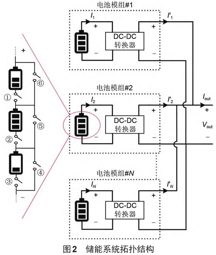
The topology structure of the parallel battery module shown in Figure 2 can adjust the output voltage and current according to the load demand, and can also independently adjust the current of each battery module based on its performance. The bypass equalization topology of the series connected battery pack within the battery module can be achieved by bypassing any single battery cell through an on/off switch, thereby achieving SOC equalization within the battery pack. Taking three battery cells with different SOC connected in series within the battery module as an example. If the battery pack is in a discharging state, turn on switches ①, ②, and ④, turn off other switches, and bypass the battery cell with the least energy. If the battery pack is in a charging state, turn on the switch ① ③ ⑤ to bypass the battery cell with the highest energy. Using the parallel connection mode of the modules shown in Figure 2, if module 2 malfunctions at this time, the output power is adjusted to 0 through a DC-DC converter, while the other battery modules still operate normally to ensure that the system can still operate normally. If traditional series technology is used, when module 2 malfunctions, the entire system will stop working. So, this not only avoids the inherent barrel effect of series battery packs, but also enables different parallel battery modules to be mutually backup, significantly improving the safety and reliability of the DC system. In addition, for each parallel battery module, the battery cells can be grouped in advance according to performance consistency, reducing the difficulty of SOC balancing within the series battery group, accelerating the speed of SOC balancing within the group, and providing favorable time conditions for the next step of life balancing between modules.
2.Equalization algorithm
The multi time scale balancing method proposed in this article for series parallel battery packs: in a short time scale, the SOC in the series battery pack quickly reaches equilibrium in a short time; On a long-term scale, adjust the charging and discharging depth of parallel battery modules based on their aging degree, in order to achieve life balance. How to coordinate the long and short time scale balance in the balance algorithm: When the SOC in the series battery pack quickly reaches balance in a short period of time, the long time scale life balance can be initiated.
2.1 Long time scale life balance control algorithm based on power weighting
The essence of balancing the lifespan of parallel battery modules is to control the discharge depth of the battery based on the health status of each module. The overall principle is: the less the remaining lifespan, the shallower the discharge depth of the battery module in that group; The more remaining life, the deeper the discharge depth of the battery module in that group. By combining the topology structure of this article and utilizing a DC-DC converter to regulate the output power of each battery module, the goal of controlling the discharge depth of the module can be achieved. Therefore, based on the above principles, this article proposes a power weighted life balance control algorithm, which first calculates the compensation SOC that each battery module should provide; Then divide the capacity of each battery module by the reference capacity to obtain a weight factor related to the charge, and use this factor to correct the SOC (i.e. normalization) of each battery module. Finally, divide the SOC of each battery module by the sum of the SOC of each battery module to obtain a weight factor for power, and based on this factor and the compensated SOC, obtain the actual power that each battery module needs to provide. The specific content of the algorithm is as follows:
After the series battery pack reaches SOC equilibrium in a short period of time, the average SOC of the battery pack is taken as the SOC of each module (assuming the number of modules is N) (SOCave1, SOCave2,…, SOCaveN), and the average capacity is the capacity of each module (Q1 to QN). Assuming the capacity relationship is Qmax=Q1>Q2…>QN=Qmin. In order to achieve life balance among parallel battery modules, the additional compensation SOC that each module should provide relative to the worst health state of the battery module can be calculated( Δ SOC), calculated as equation (1):
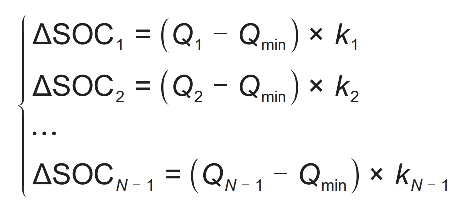
In the formula, k1~kN-1 are the proportional coefficients, expressed in 1/Ah. The values of k1-1-kN-1 may not necessarily be equal, and the values need to be adjusted based on the capacity difference of each module. In this article, the values of 8-10 can achieve the best adjustment result. This proportional coefficient can not only convert the unit of capacity to “1”, but also adjust the proportional coefficient appropriately to Δ SOC is more suitable for the difference in lifespan between modules.
If the weight factor is directly calculated based on the current SOC of each module (i.e. SOCave1, SOCave2,…, SOCaveN) when balancing the lifespan of parallel battery modules, it is obviously not in line with the actual situation. Because SOC is defined as the ratio of remaining available power to battery capacity, which is only a relative value. When the aging degree of each module is different, the corresponding electric quantity of SOC changes is also different. If the aging degree of battery pack 1 is higher than that of battery pack 2, the corresponding amount of SOC change in battery pack 1 will be lower than that of battery pack 2. Therefore, the algorithm should first normalize the SOC of each module to the same level (with optional reference values for normalization), in order to facilitate comparison and quantification between parallel battery packs. Assuming that the algorithm chooses to normalize the SOC of all modules with the maximum capacity Qmax as the reference value, the SOC of each parallel module will be converted into SOC’ave1-SOC’aveN:
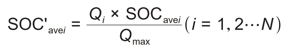
In the formula, SOC’avi is the SOC of each battery module at the same level.
In order to achieve a balanced lifespan of parallel battery packs, it is necessary to allow healthy battery packs to bear more power output. Therefore, the normalized SOC of each battery pack and the pending compensation can be utilized Δ SOC, which comprehensively determines the instantaneous power P1 to PN that each battery pack should provide:
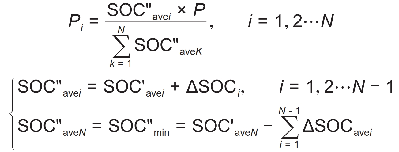
In the formula, P is the total power required by the load; Pi is the output power that each parallel module should provide. By controlling the discharge depth of battery modules according to the above method, the discharge depth of battery modules with good health status will be deeper, while that of battery modules with low health status will be shallower. This method presents a virtuous cycle of charging and discharging for all parallel battery modules, ultimately achieving the end of life for each battery module simultaneously, reducing the number of battery replacements, and facilitating operation, maintenance, and cascade utilization.
2.2 Short time scale series battery pack balancing algorithm based on SOC bypass
The basic strategy of the SOC bypass equalization algorithm for series battery packs is to determine whether the battery pack needs to be balanced based on the standard deviation of the SOC value of the battery pack. If the standard deviation of the battery pack SOC is less than the set threshold, it indicates that the battery pack SOC does not need to be balanced, and the battery pack operates in series. If the standard deviation of the battery pack SOC is greater than the set threshold, it is necessary to perform bypass equalization on the battery pack. Assuming that the battery pack needs to bypass the Nbypass block monomer, determine the charging and discharging status of the battery pack at this time. If the battery pack is discharged, bypass the battery cell with the lowest energy in the Nbypass block by controlling the switch array; If the battery pack is charged, bypass the highest energy cell of the Nbypass block by controlling the switch array.
3 Simulation verification
3.1 Battery model
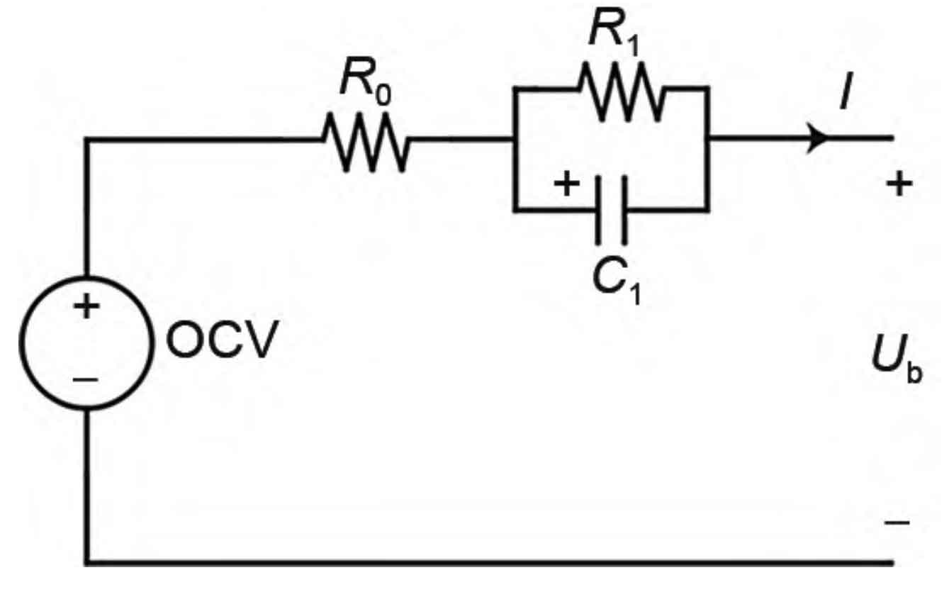
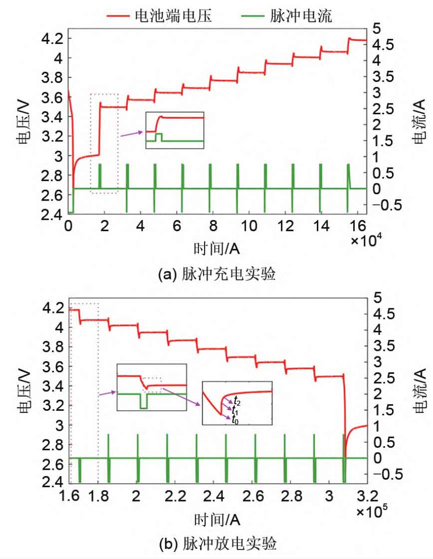
Building a lithium battery model that reflects both electrical and aging characteristics is crucial for the validation of the multi time scale equilibrium strategy proposed in this paper. The battery model in this article is a first-order RC model established based on hybrid pulse power characterization (HPPC) cyclic discharge experiments and accelerated aging experiments, as shown in Figure 3. R0, R1, and C1 represent the ohmic internal resistance, polarization internal resistance, polarization capacitance, and Ub represent the battery terminal voltage, respectively. The basic principle of HPPC testing is to use a series of charging and discharging pulses to act on different SOC of the battery to calculate the internal resistance at different charging and discharging rates, as shown in Figure 4 (a) and (b). The ohmic internal resistance (R0) of the battery can be calculated based on the change in battery terminal voltage during the quiescent phase after the end of the pulse current (i.e. t0 to t1 stages). Due to the fact that the voltage at both ends of the capacitor cannot suddenly change, the voltage at both ends of the battery during the quiescent phase will exhibit an exponential trend (i.e. t1 to t2 stages). Using this exponential trend, the polarization internal resistance (R1) and polarization capacitance (C1) of the battery can be calculated. At the same time, the OCV of the battery can also be obtained after the quiescent phase (t1 to the next pulse addition phase) ends. Therefore, using this method, equivalent circuit model parameters (R0, R1, C1, OCV) corresponding to different SOC can be obtained. The specific calculation method is as follows.
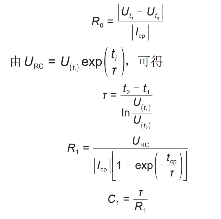
In the formula, TCP is the duration of the current pulse; Icp is the size of the current pulse; τ Is the time constant of the first-order RC circuit.
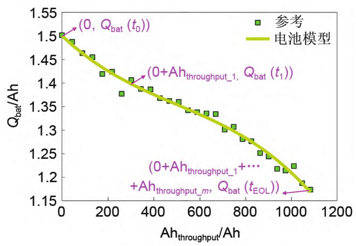
The battery capacity Qbat will decrease with battery aging, and the modeling of the evolution law of Qbat is mainly based on the calibration value of battery capacity. Battery aging is manifested as the attenuation of battery capacity, and its fundamental reason is the continuous accumulation of damage during the charging and discharging process, which can be reflected by the accumulated amount of ampere hours. Therefore, by analyzing the results of the accelerated aging test of lithium batteries, an approximate relationship between Qbat and Ahthoughput can be obtained, as shown in Figure 5. Assuming that the capacity of the new battery is Qbat (t0), after charging and discharging cycles, the capacity of the battery decays to Qbat (t1). During this process, the cumulative ampere hour of the battery is Ahthroughput_ 1. If further charging and discharging cause the battery capacity to decay to Qbat (t2), the cumulative ampere hours during the decay process from Qbat (t1) to Qbat (t2) can be obtained as Ahthoughput_ 2. By analogy, it can be obtained that the cumulative ampere hours during the entire process of the battery capacity decay from Qbat (t0) to Qbat (tEOL) are respectively Ahthoughput_ 1. Ahhroughput_ 2… Ahthroughput_ M. In practical applications, for current accumulation, it is easy to obtain the cumulative ampere hour of the battery [Equation (9)], therefore, the current capacity Qbat of the battery can be obtained in a timely manner through the model.

By using interpolation method, unknown quantities within a specific interval can be obtained based on known data points, in order to solve the problem of discrete measurement points in the battery modeling process mentioned above. In order to obtain the unknown parameters corresponding to the interval SOC ∈ [0%, 100%] and Ahthoughput ∈ [0, ∞], this paper uses the following third-order Hermite interpolation method:
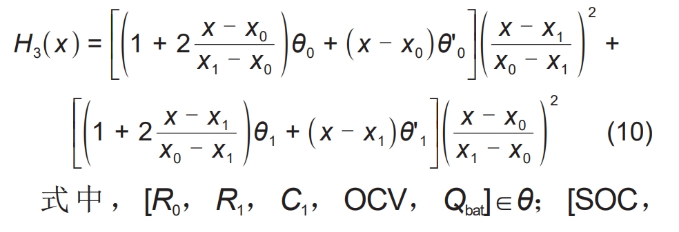
In the formula, [R0, R1, C1, OCV, Qbat] ∈ θ; [SOC, Ahthroughput] ∈ x; X0 and x1 are the positions of two adjacent points to be interpolated; θ 0 θ 1 is the dependent variable corresponding to the independent variables x0 and x1; θ’ 0 θ’ 1 is the corresponding derivative.
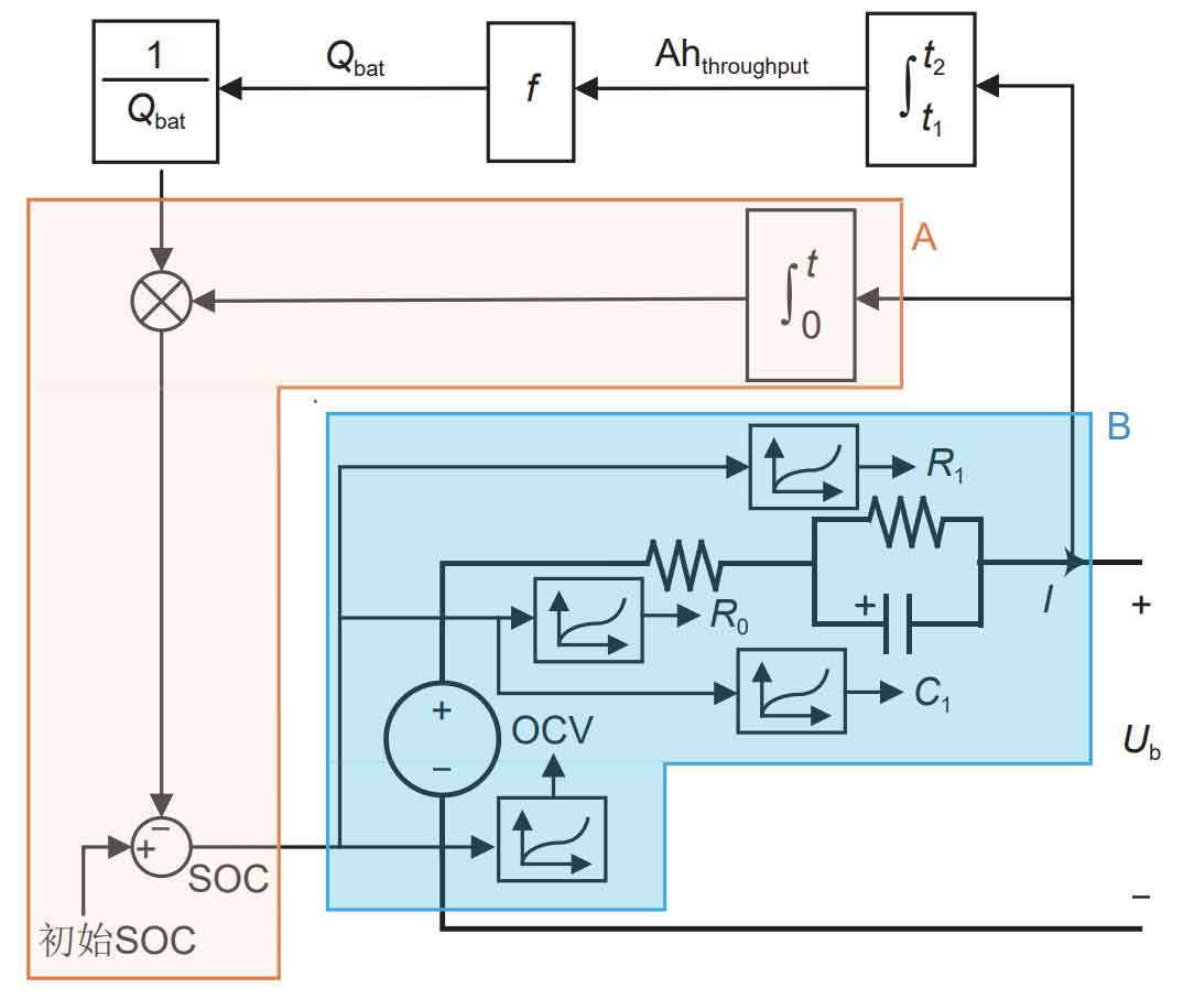
Figure 6 is a schematic diagram of the lithium-ion battery aging model. After obtaining the current capacity Qbat of the battery, update the current SOC of the battery in real-time based on the ampere hour integration method (as shown in Part A of Figure 6). Because all parameters of the first-order RC model are related to SOC, the equivalent circuit model parameters can be updated based on the current SOC of the battery (as shown in Part B of Figure 6).
3.2 Algorithm validation
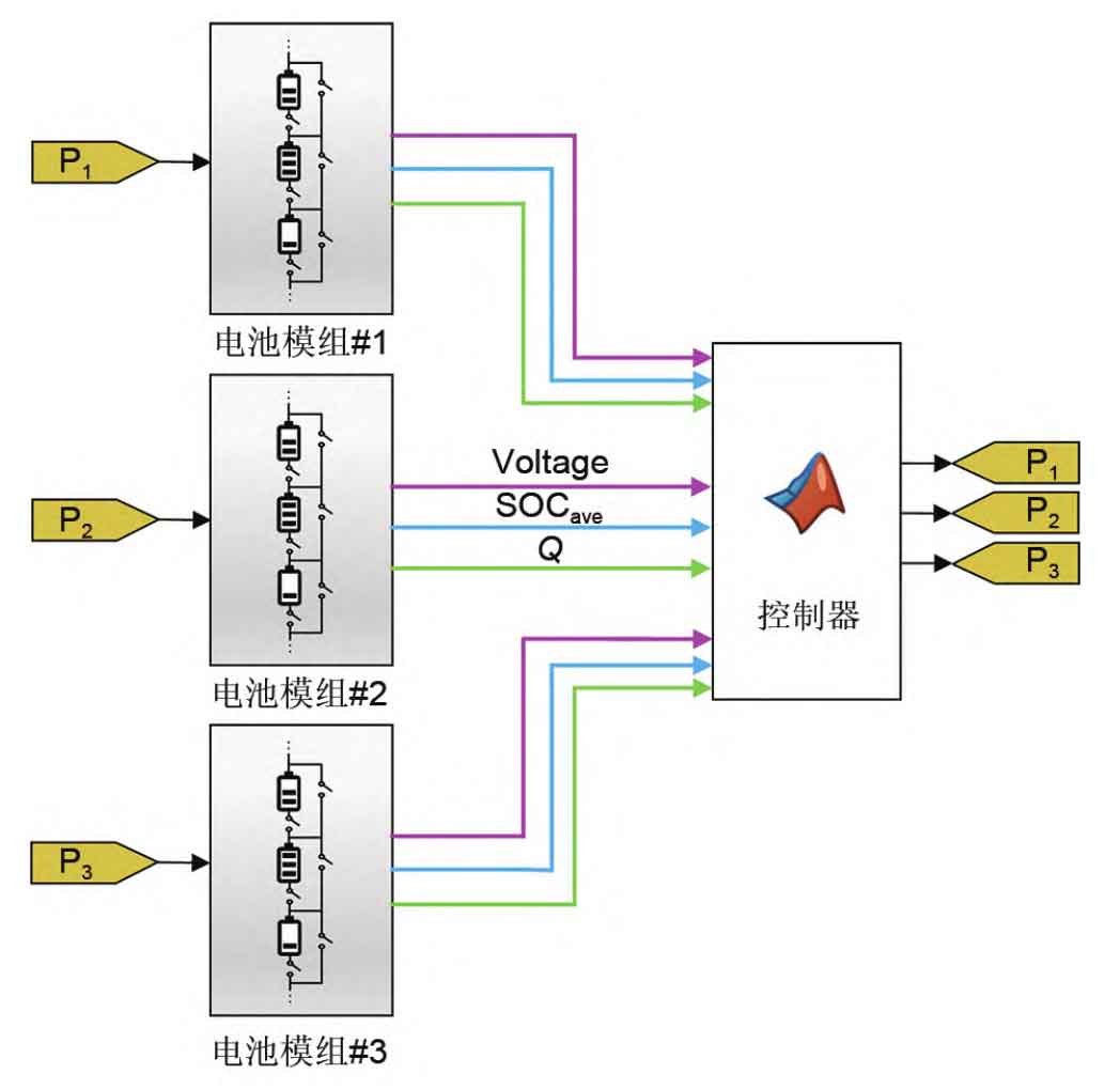
In order to verify the effectiveness of the proposed algorithm, three sets of comparative experiments were designed and a small energy storage system consisting of three parallel battery modules was built using the MATLAB/Simulink simulation platform. Three parallel battery modules were composed of six battery cells in series (6S3P), and a constant power load of P=500 W. Figure 7 is a simulation diagram of the energy storage system, and the controller contains a complete equalization algorithm. The controller outputs the power that the battery module needs to output based on parameters such as battery module voltage, SOC, and capacity, and feeds back this power to each battery module. Assuming that the three parallel battery modules of the 6S3P model are named M1, M2, and M3 respectively. SOCi, j (i=1, 2, 3; j=1, 2… 6) represents the SOC of the battery cell j in module i. The initial SOC of the battery cells within the module is set to [SOCi, 1, SOCi, 2, SOCi, 3, SOCi, 4, SOCi, 5, SOCi, 6]=[95%, 96%, 92%, 90%, 85%, 84%], and the initial capacity of each module is set to [M1, M2, M3]=[1.5019 Ah, 1.4878 Ah, 1.4637 Ah], and the OCV of each battery module will change with the initial capacity of the module.
In order to verify the effectiveness of the proposed equalization algorithm, three sets of comparative experiments were designed:
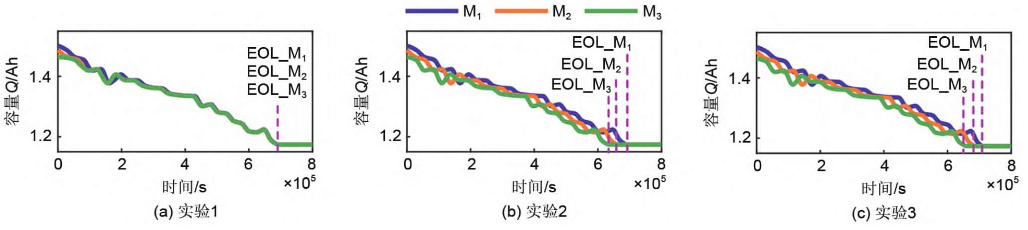
Experiment 1: The multi time scale equalization method proposed in this article [Figure 7 (a), Figure 8];
Experiment 2: SOC equalization was only performed within the battery module group, with imbalance between parallel battery modules [Figure 7 (b), Figure 9];
Experiment 3: There is no equalization within the battery module group or between parallel battery modules [Figure 7 (c), Figure 10].
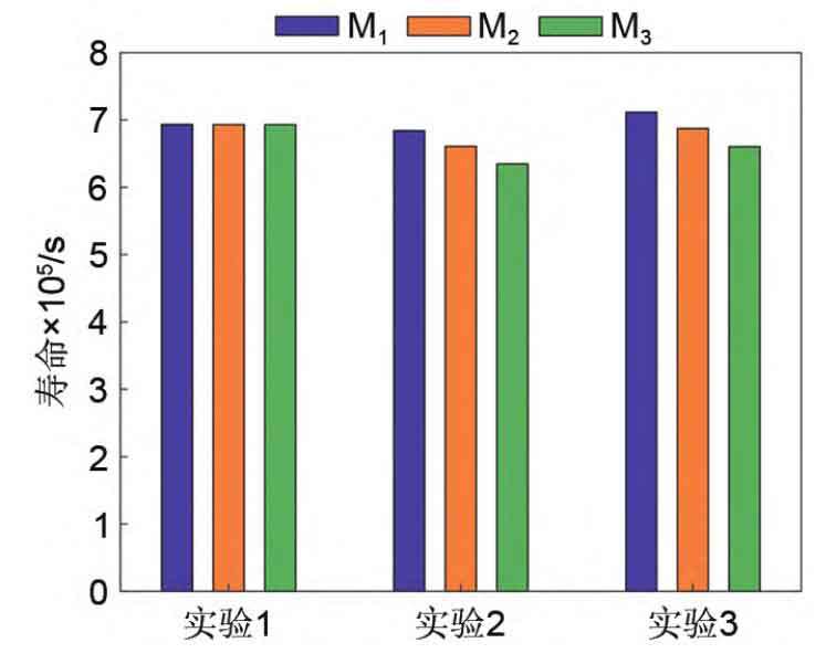
Figures 7 (a) to (c) show the curves of the capacity of each battery module over time in three experiments; Figures 8 (a) to (c) show the curves of the SOC of the individual cells in each battery module group over time in Experiment 1, respectively; The subgraph distribution of Figures 9 and 10 is the same as Figure 8. Figure 11 shows the time when each parallel module in the 6S3P small energy storage system reached its end of life in experiments 1-3. From Figure 7 (a), it can be seen that using the proposed equalization algorithm in this article, modules with different degrees of aging can simultaneously reach their end lives (i.e. EOL_M1=EOL_M2=EOL_M3). Figures 7 (b) and (c) show that only using SOC equalization within the battery module group and not using equalization algorithms within or between the battery modules cannot achieve the end of life of each battery module at the same time on a long-term scale (i.e. EOL_M1>EOL_M2>EOL_M3). The results in Figure 7 indicate that the multi time scale equalization algorithm proposed in this paper is effective.
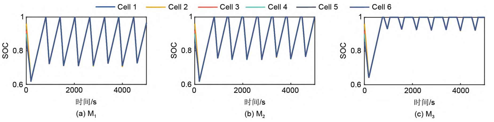
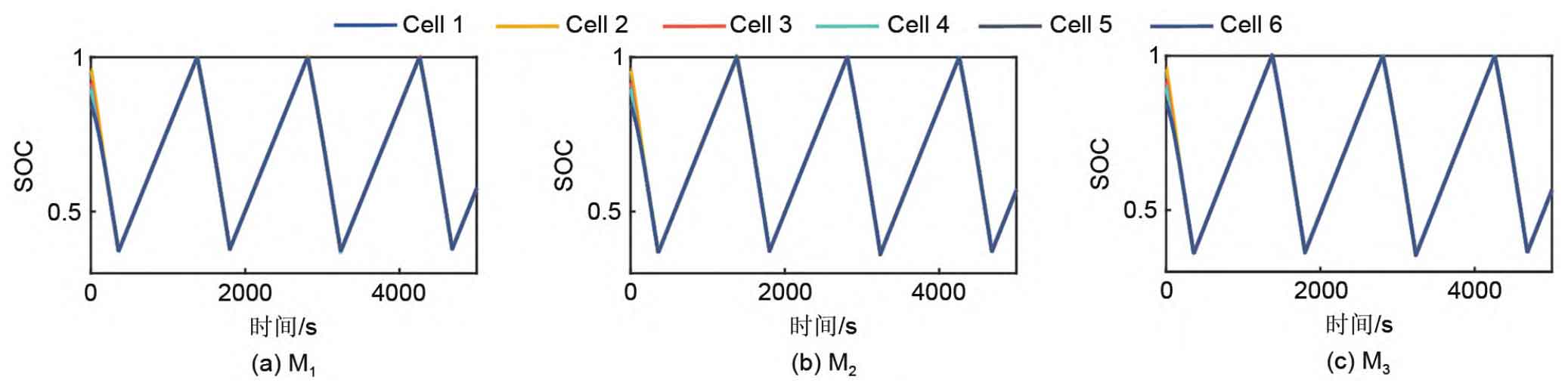
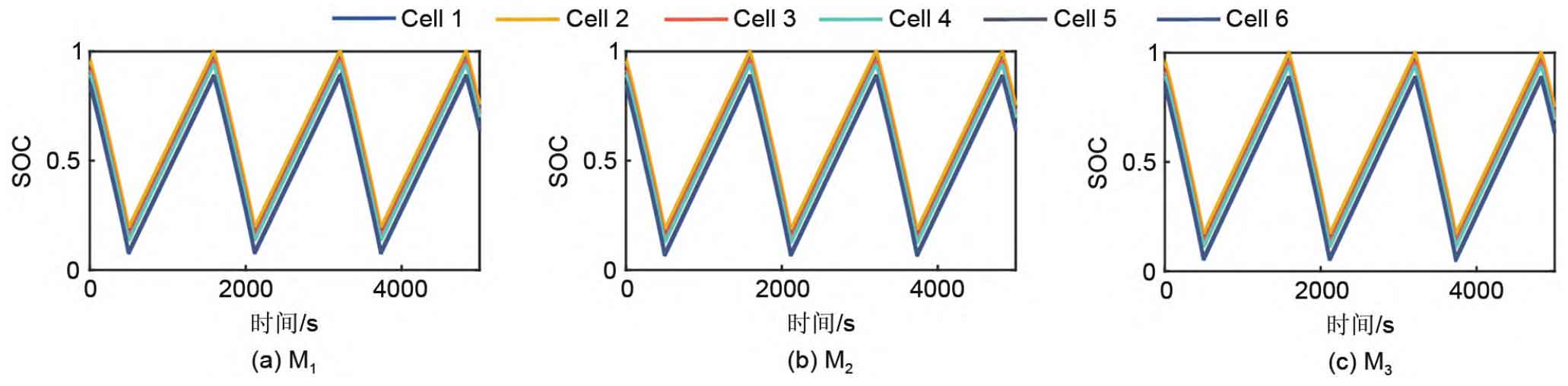
As shown in Figure 8, after using the equalization algorithm proposed in this article, the SOC within each battery module can remain consistent during operation. But the discharge depth is different, that is, the battery module M1 with the best health state has the deepest discharge depth, and the battery module M3 with the most aging degree has the shallowest discharge depth. This is the key to maintaining a balanced lifespan of the battery module over a long period of time, and also indicates the effectiveness of the proposed multi time scale balance strategy in balancing the long and short time scales. Although it can be seen from Figure 9 that under the condition of using SOC equalization only within the battery module group, the individual SOC of each parallel battery module group can be balanced. However, the depth of discharge does not vary depending on the degree of aging of the parallel modules. So the equalization process achieved in Experiment 2 has no positive significance for achieving the life balance of battery modules on a long-term time scale. However, Figure 10 shows that when the equalization algorithm is not used within or between battery modules, the single SOC of batteries in parallel modules cannot maintain equilibrium, and the discharge depth of each battery module reaches almost 100%. According to Figure 11, the lifespans of M1 to M3 in Experiment 1 were 693298 s, 693083 s, and 693084 s, respectively; The lifespans of M1 to M3 in Experiment 2 were 684051 s, 660828 s, and 634667 s, respectively; The lifespans of M1 to M3 in Experiment 3 were 711607 s, 687305 s, and 660229 s, respectively. In addition, in Experiment 1, the average lifespan difference of each module was 143 seconds, with a maximum lifespan difference of 215 seconds. In Experiment 2, the average lifespan difference of each module was 32923 seconds, with a maximum lifespan difference of 49384 seconds. In Experiment 3, the average lifespan difference of each module was 34252 seconds, with a maximum lifespan difference of 51378 seconds. Therefore, from the experimental data of three sets of experiments, it can be seen that the lifespan of the three parallel modules in Experiment 1 is almost the same, while the lifespan difference between the three parallel modules in Experiment 2 and Experiment 3 is very large. For experiments 2 and 3, if M2 and M3 reach their end of life in advance, the parallel modules no longer have a backup relationship with each other, resulting in reduced system reliability and requiring timely replacement of battery modules by operation and maintenance personnel. The more parallel battery modules there are, the higher the cost of operation and maintenance. If the method proposed in this article is applied to actual stations, the high reliability of the backup power supply system can be guaranteed throughout the entire operation process, and only one operation and maintenance of the backup power supply is required when each module reaches its end of life. In addition, in Figure 11, the average lifespan of each battery module in Experiment 1 is 693155 seconds, while in Experiment 2, the average lifespan of each battery module is 659849 seconds. Therefore, by comparing Experiment 1 and Experiment 2, it can be seen that using the multi time scale equalization algorithm proposed in this article can extend the average lifespan of the system while keeping the SOC of the battery cells within the battery module consistent. This indirectly indicates that only considering the equilibrium of the battery at the short time scale and not considering the equilibrium of the battery at the long time scale cannot maximize the utilization of battery energy at the long time scale.
Based on the comprehensive comparison of three sets of experimental data, it can be seen that the equalization algorithm proposed in the article has the following advantages: ① The battery module can maintain SOC balance throughout the operation of the battery, avoiding overcharging or discharging of battery cells. ② Parallel battery modules can simultaneously reach the end of life, avoiding multiple replacement of battery modules and reducing operation and maintenance costs.
4 Conclusion
A multi time scale balancing method for parallel lithium-ion battery energy storage systems is proposed to address the “cask effect” of traditional series technology solutions for backup power sources and the inconsistency of SOC and inter group lifespan within battery modules in parallel solutions. The core idea of this method is to perform bypass balancing within the battery module group to achieve SOC balancing in a short time scale, and to perform life balancing between parallel battery modules to achieve a unified cut-off life for each battery module group in a long time scale.
In order to design the balancing method reasonably, a multi time scale balancing algorithm was designed based on the working characteristics of the battery, including the SOC bypass balancing algorithm within the battery module group and the power weighted life balancing control algorithm. In order to verify the feasibility and effectiveness of the proposed equalization algorithm, HPPC and accelerated aging tests were conducted on lithium batteries. Based on the experimental data, a lithium battery aging model was established. Finally, three sets of comparative experiments were designed. The experimental results show that the multi time scale equalization algorithm proposed in the article can not only maintain SOC balance within the battery module, but also enable all battery modules to reach the end of their lifespan simultaneously over a long time scale, taking into account the consistency of individual SOC and battery module lifespan. This not only solves the wooden barrel effect of series battery packs, but also reduces the number of battery replacements and reduces the operation and maintenance costs of the system.