
As of the end of November 2022, China’s wind and photovoltaic installed capacity accounted for 28.8% of the country’s total installed capacity. The installed capacity of wind and solar power increased by 15.1% and 29.4% year-on-year, respectively, and is currently in a rapid development stage. The high proportion of new energy grids has adapted to the development trend of the future world. However, new energy sources such as wind power and photovoltaic have the characteristics of volatility and uncertainty, and their large number of grid connections will increase the difficulty of system frequency regulation. Regarding the control characteristics of new energy, on the one hand, due to the fact that new energy generation units are usually in maximum power point tracking mode, they do not have the ability to adjust the output power of new energy units to compensate for the imbalance of system active power; On the other hand, wind turbines achieve grid connection regulation through power electronic control, which decouples the rotor speed and system frequency, and basically does not have inertia response ability, thus reducing the inertia response ability of the system. Therefore, the large-scale integration of new energy into the grid will pose challenges to the frequency stability of the power grid, and even lead to a series of problems such as frequency instability in the power system.
Energy storage, as one of the effective means to solve the above problems, has the following effects on regional power grids containing a high proportion of new energy:
(1) Reduce system frequency fluctuations;
(2) Improving the economy of energy storage assisted power grid frequency regulation;
(3) Improve the power quality and risk resistance of the system.
The type, placement, energy capacity, and charging and discharging power of energy storage jointly determine the quality of the optimized configuration of energy storage. At present, the main types of megawatt level frequency modulation energy storage at home and abroad, except for pumped storage, are electrochemical energy storage. The frequency modulation operation modes mainly include assisting traditional power frequency modulation, relying on large-scale new energy to participate in frequency modulation, and independent grid connected frequency modulation in the transmission and distribution process. Compared to energy storage, assisting traditional power frequency modulation and relying on large-scale new energy to participate in frequency modulation do not involve site selection, and the complexity is relatively low, The flexibility of independent grid connected frequency regulation in the energy storage transmission and distribution process is higher, and its auxiliary regional power grid frequency regulation effect is better.
In order to achieve optimal configuration of energy storage systems with frequency modulation control under a high proportion of new energy, it is first necessary to study a control method for energy storage to participate in the primary frequency modulation of the system. The research direction of control strategies for energy storage providing frequency support can be as follows: firstly, for energy storage converters, virtual synchronous machine control can be used to establish a prediction model for energy storage converters, and real-time correction of their input active power can be achieved to achieve frequency modulation. The second is to study the control strategy of battery energy storage participating in frequency modulation, efficiently utilizing the precise and fast output characteristics of battery energy storage to achieve the best frequency modulation effect. The control methods for battery energy storage participating in frequency modulation mainly include virtual droop control and virtual inertial control. The battery energy storage adopts virtual droop control and proposes a comprehensive control strategy for energy storage primary frequency modulation based on energy storage frequency modulation coefficient and state of charge (SOC). However, the above literature did not consider the relationship between the primary frequency modulation capability of energy storage and its configuration capacity. Therefore, the energy storage capacity configuration method that considers the participation of energy storage in the primary frequency modulation effect has received attention. On this basis, some scholars analyzed the technical and economic model of energy storage batteries participating in primary frequency regulation in high proportion new energy systems, and proposed a configuration method for the rated power and capacity of energy storage. According to the frequency requirements of the power grid, the maximum power fluctuation that the system can withstand decreases with the increase of the proportion of renewable energy. Some scholars have proposed a method to quantitatively compensate for the inertia of the power grid and the reserve capacity of primary frequency regulation. This method aims to improve the system’s primary frequency regulation capability and maintain the system’s inertia unchanged, and configures the capacity and rated power of energy storage. In summary, currently, research on the optimization configuration of energy storage for frequency modulation functions mostly focuses on energy storage control strategies or capacity configuration, while there is relatively little research on multi-objective optimization that considers both location selection and capacity allocation for energy storage.
To address the above issues, this article first proposes a nonlinear variable K-coefficient energy storage control strategy, in which the frequency modulation effect of energy storage depends on its configured capacity and control parameters. Therefore, optimization of its control parameters is carried out, and on this basis, a configuration method for energy storage capacity selection suitable for frequency modulation function in high proportion new energy regional power grids is proposed. A model for energy storage capacity selection is established with the configuration goal of minimizing frequency fluctuation index, grid vulnerability index, and energy storage cost index. By calculating the weights of each objective using the information entropy method, the optimal solution is determined to achieve optimal configuration of energy storage capacity selection. Finally, based on actual simulation analysis, the effectiveness and superiority of the proposed energy storage fixed capacity location configuration method and control strategy were verified.
1.Control strategy for energy storage participating in frequency modulation under high proportion of new energy
1.1 Dynamic model of energy storage participating in primary frequency regulation
When studying the participation of energy storage in primary frequency regulation of power systems, based on the principle of regional equivalence, generator units of the same type and nature in the system are equivalent to one unit, and their capacity is the sum of all unit capacities. It can be seen that the unit regulated power of equivalent synchronous units in the regional power grid is:
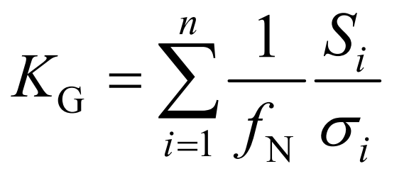
In the formula: n is the number of synchronous units in the region; Nf is the rated frequency of the system; σ I and i S are the adjustment coefficients and rated power of synchronous unit i.
Ignoring the differences in the adjustment coefficients of different generator units, let the proportion of new energy in the regional power grid be ζ, The maximum power support that the system can provide through primary frequency modulation Δ PGs are shown in equation (2).
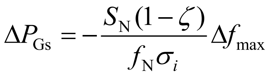
In the formula: N S is the total power generation capacity of the regional power grid; Max Δ F is the maximum frequency deviation allowed by the system.
Similarly, the maximum allowable power deviation of the system can be obtained Δ The relationship between Psysh and inertia constant is shown in equation (3). In summary, when the total power generation capacity of the system remains unchanged, with the proportion of new energy ζ As the power grid increases, both the primary frequency regulation capability and system inertia will decrease. The dynamic model of energy storage participating in primary frequency regulation in a high proportion new energy system is shown in Figure A1 of Appendix A.
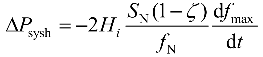
In the formula, dfmax/dt is the maximum allowable frequency change rate of the system; Hi is the inertia constant of synchronous unit i. In this article, the energy storage adopts both virtual droop control and inertia control for frequency modulation.
1.2 Energy Storage Primary Frequency Modulation Control Strategy Based on Nonlinear Variable K-Coefficient
Under virtual droop control, energy storage will simulate the droop characteristics of synchronous generator sets, that is, when the system load disturbance causes frequency deviation, energy storage can quickly respond, reduce the active power imbalance of the system, and thus reduce the steady-state frequency deviation of the system. During this process, the relationship between the energy storage output and the system frequency deviation is:
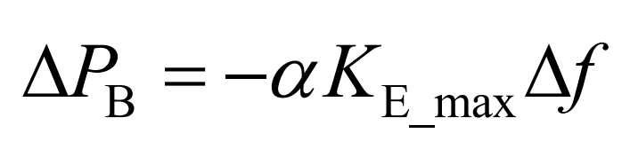
In the equation: Δ PB is the energy storage output; KE_ Max is the maximum unit regulated power for energy storage; α Is the variable K coefficient; Δ F is the system frequency deviation.
To avoid frequency fluctuations caused by sudden stop of output after energy storage SOC depletion or saturation, variable K-coefficient control is usually used. However, the frequency modulation capability of energy storage using conventional linear variable K droop control will not be sufficient to meet the requirements. Therefore, nonlinear variable K-coefficient control is adopted to make the energy storage droop control coefficient exhibit an S-shaped change with respect to SOC, and different S-shaped changes are set inside and outside the frequency regulation dead zone of traditional thermal power units. Outside the frequency modulation dead band, the energy storage is in the frequency modulation stage, and its coefficient α It can be expressed as:
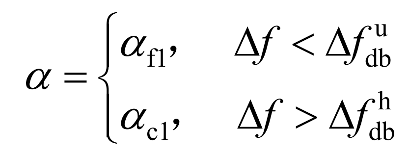
In the equation: Δ Fudb Δ Fhdb represents the lower and upper limits of the frequency modulation dead band, respectively; α F1 α C1 is the variable K coefficient for energy storage discharge and charging, respectively, and α F1 α The variation of c1 with SOC is shown in equations (6) and (7).
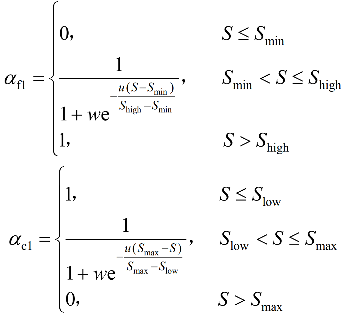
In the formula, Smin, Slow, Shigh, and Smax are the lower limit, smaller value, higher value, and upper limit of energy storage SOC, respectively; S is the state of charge for energy storage; w. U is the adaptive parameter of the curve.
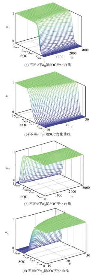
In the frequency modulation stage, the function curve of the variable K coefficient with respect to SOC is shown in Figure 1. From Figure 1, it can be seen that using nonlinear variable K-coefficient control can reduce the frequency disturbance and the possibility of overcharging and discharging caused by energy storage due to stopping output. When w and u take different values, the unit regulated power of energy storage will also be different. Therefore, by optimizing w and u as decision variables, energy storage can participate in primary frequency regulation better, while avoiding rapid depletion or saturation of SOC.
In the frequency regulation dead zone of traditional thermal power units, an additional energy storage droop control coefficient is set to enable energy storage to recover to the ideal SOC state. This not only fully utilizes the advantage of fast battery energy storage response speed, but also improves the effect of energy storage participating in primary frequency modulation. During the SOC recovery phase, the frequency modulation coefficient of energy storage is changed to K coefficient α Represented as:
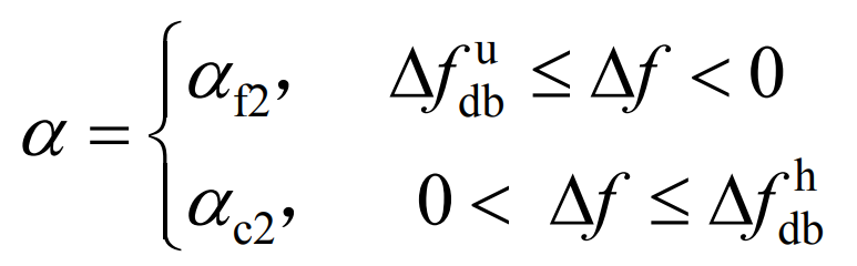
In the equation: α F2 α C2 is the variable K coefficient for energy storage discharge and charging, respectively, and α F2 α The variation of c2 with SOC is shown in equaztions (9) and (10).
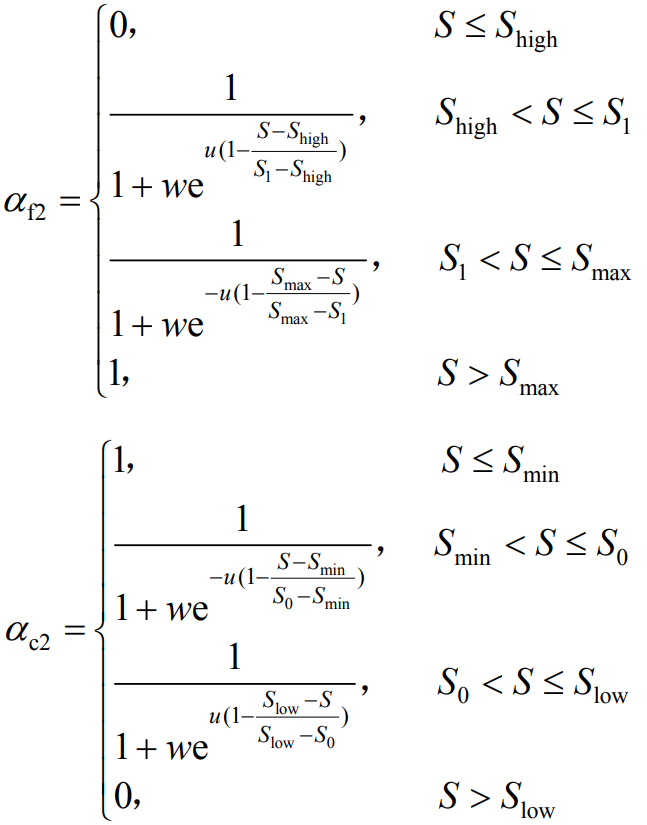
In the equation, S0 and S1 are the lower and upper intermediate values of SOC, respectively. During the SOC recovery phase, when energy storage participates in frequency modulation, its SOC will approach towards the middle, restoring the energy storage SOC to an ideal state. The coefficient of the energy storage recovery phase α The function curve of SOC is shown in Figure 2.
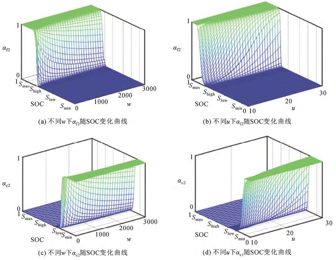
According to equations (9) and (10), whether the energy storage is operating in the frequency modulation stage or the SOC recovery stage, its droop control coefficient will vary with the difference in Slow and Shigh. That is to say, if different Slow and Shigh settings are set, it will affect the frequency modulation effect of energy storage. Therefore, optimizing the energy storage control parameters Low, Shigh, w, and u is very necessary. This section will be discussed in the following chapters.
3.Parameter optimization of energy storage system participation in primary frequency regulation
Due to its obvious optimization results, fast convergence speed, and easy parameter setting, particle swarm optimization (PSO) algorithm is widely used in optimization problem solving. The speed and position update formula for standard PSO is:
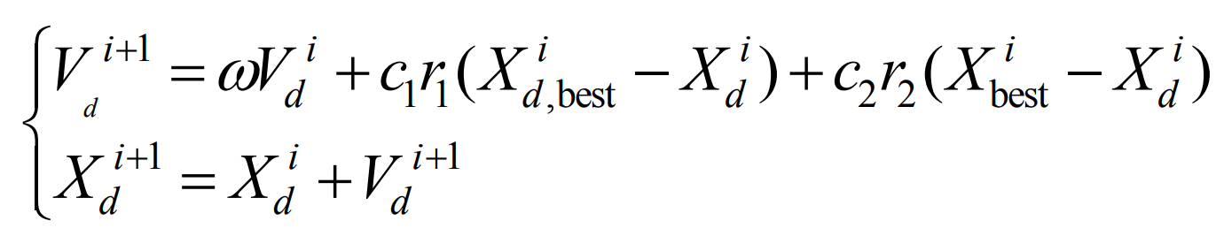
In the formula: i represents the number of iterations that have been made; D represents the particle number; Vid and Xid are the velocity and position of particle d before updating; Vi+1d and Xi+1d respectively represent the updated speed and position; Xid, besr, and Xibet are the optimal positions for particle d and population, respectively; ω Is the inertia weight; C1 and c2 represent learning factors; R1 and r2 represent random numbers between 0 and 1.
Although standard PSO is more widely used than other intelligent algorithms, it is prone to low convergence accuracy, difficulty in convergence, or falling into local optima when solving multi-objective energy storage planning problems due to the lack of dynamic adjustment of speed. To solve these problems, it is necessary to adjust the inertia weight ω Make improvements to link it with the position of the particle swarm and the real-time operation process, as shown in equations (12) and (13). Firstly, as the number of iterations increases, ω Decreasing, enhancing the search ability of particle swarm in the early stage and the convergence ability in the later stage; Secondly, when the particle swarm is relatively discrete, that is, when the current optimal particle position is far from the position of other particles ω Set to a smaller value to improve individual search ability; On the contrary, when the distance is small, set ω Larger to improve global search ability and reduce the possibility of premature puberty.
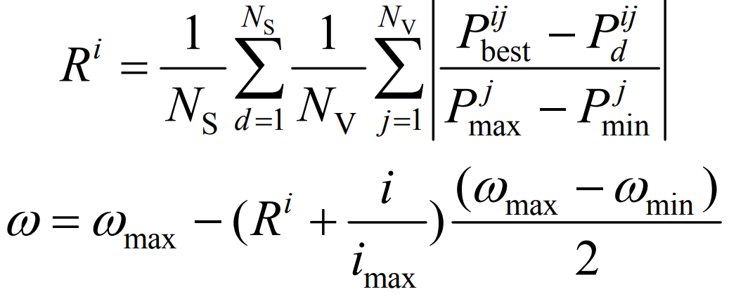
In the formula, Ri represents the dispersion of the particle swarm during the iteration process; Imax is the maximum number of iterations; NS and Nv are the total number of particles and decision variables, respectively; Pjmin, Pjmax, Pijbest, and Pijd are the minimum and maximum values of the jth decision variable, the minimum value of the iteration process, and the value of the d-th particle, respectively; ω Min ω Max is the minimum and maximum values of the inertia weight, respectively.
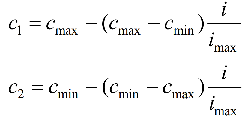
From the speed update formula, it can be seen that increasing c1 and c2 is beneficial for individual optimal search and group optimal search, respectively. In the early stage of the operation, a larger c1 and a smaller c2 are set, while in the later stage of the operation, the opposite is set, as shown in equations (14) and (15), to increase the diversity of the algorithm and avoid falling into local optima, where cmin and cmax are the minimum and maximum values of the learning factor, respectively.
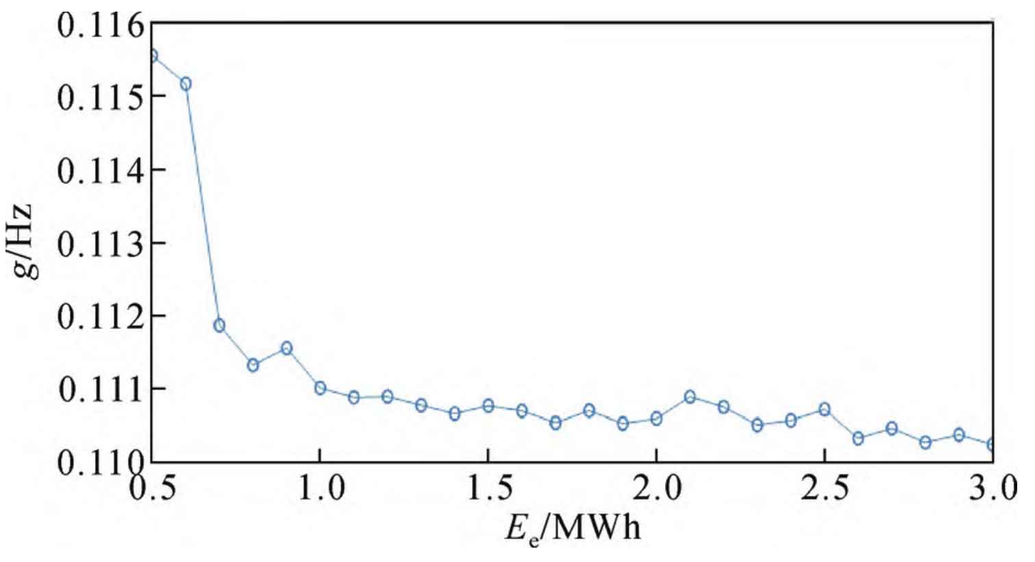
Establish the dynamic model shown in Figure A1 of Appendix A in MATLAB/Simulink, and incorporate step perturbations. The improved PSO algorithm was used to optimize the objective function g shown in equation (16), resulting in the results shown in Table A1 in Appendix A. After parameter optimization, the value of the objective function changes with the energy storage capacity as shown in Figure 3. Due to differences in energy storage capacity, the optimization time period may vary slightly, which may result in larger capacity and higher objective function values in some cases. However, overall, as the energy storage capacity increases, the ability to assist in frequency modulation also becomes stronger.
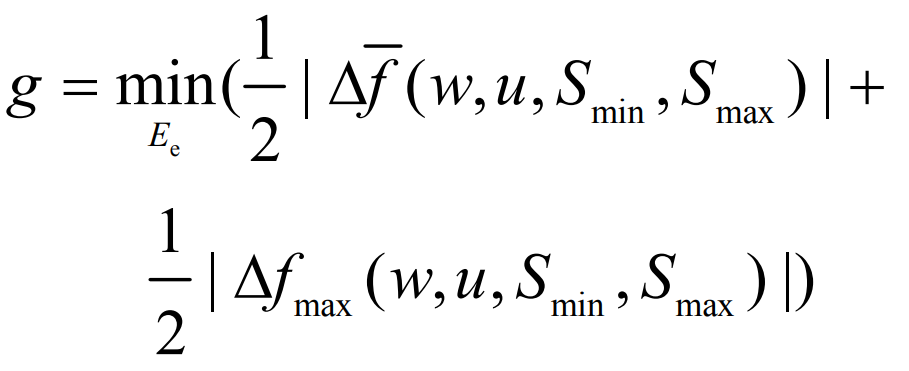
In the equation: Δ F Δ Fmax is the average frequency deviation and maximum frequency deviation of the response process, respectively; Ee is the energy capacity of the energy storage configuration.
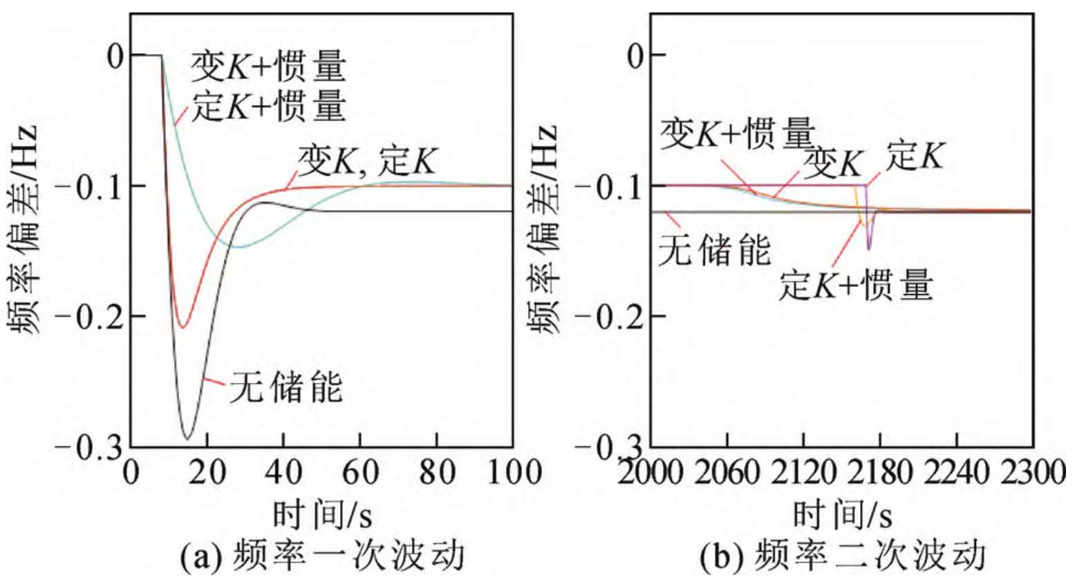
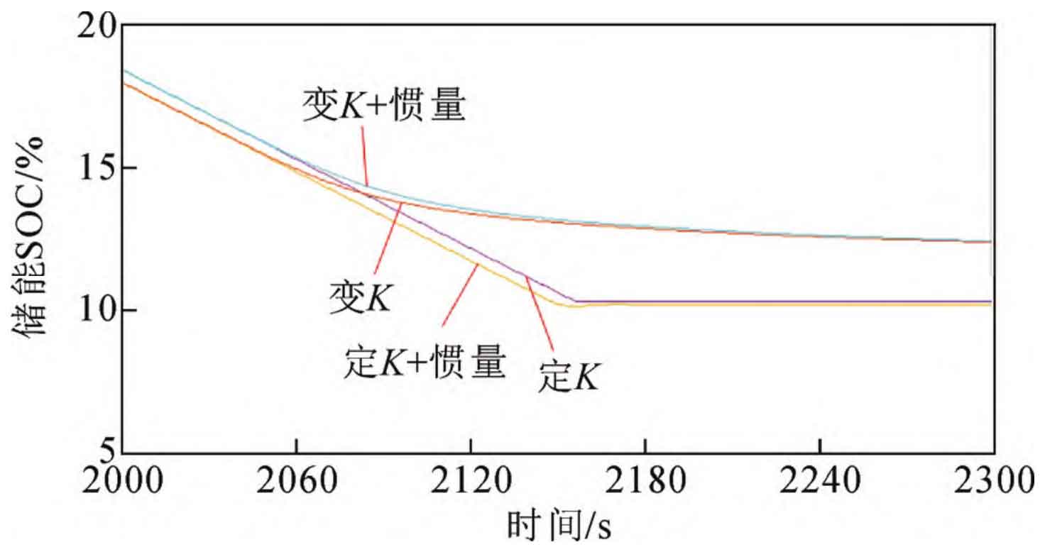
Taking Ee=3 MWh as an example, the optimization results for w, u, Slow, and Shigh are 816, 220, 45, and 55, respectively. Taking a reference value of 200 MW and adding a step disturbance of 0.05 (p.u.) at t=8 s, the system frequency deviation and energy storage SOC changes are shown in Figures 4 and 5, respectively. From the figure, it can be seen that compared to other control methods, the energy storage adopts variable K coefficient+inertia control, which can reduce the frequency fluctuation caused by load disturbance. In addition, the frequency secondary fluctuation caused by the sudden cessation of output after the depletion or saturation of the energy storage SOC is also small, while ensuring that the energy storage SOC does not exceed the limit.
3.Multi-objective Optimization Configuration Model for Energy Storage under High Proportion
3.1 Objective function
1) Frequency fluctuation index
In response to continuous load disturbances within the regional power grid, the average of the maximum frequency deviation and frequency deviation can reflect the degree of system frequency fluctuations. This objective function can be expressed as:
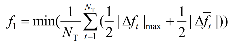
In the formula: NT is the total number of sampling cycles| Δ Ft | max is the maximum frequency deviation within period t| Δ Ft | is the average frequency deviation within period t.
2) Grid vulnerability indicators
In order to quantitatively represent the improvement degree of energy quality by adding energy storage to the grid side, this paper proposes a grid vulnerability index. Starting from the safety of grid operation, it measures the power quality and risk resistance ability of the grid by analyzing the degree of voltage deviation standards at each node and the balance of node voltage distribution. The higher the vulnerability, the more unstable the power grid in the region, the lower the power quality, and the poorer the risk resistance ability. The goal of minimizing the average vulnerability index of the system can be expressed as:
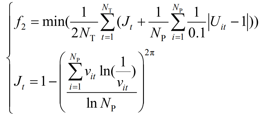
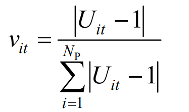
In the formula: Np is the total number of nodes; Uit is the voltage per unit value of node i at time t; Vit is the ratio of node i voltage offset to the sum of current grid voltage offset, as shown in equation (19); TJ is the equilibrium degree of the grid voltage offset, with a larger value representing greater imbalance, and its value range is 0-1.
3) Energy storage cost indicators
The participation of energy storage in frequency regulation can improve the stability of power system operation and the quality of power grid energy, and its investment cost should be considered as an important factor in configuring energy storage. The annual cost value of energy storage investment can be calculated based on the full life cycle theory, and its cost composition mainly consists of two parts: initial investment cost and operation and maintenance cost. Therefore, with the objective function of minimizing the annual value of the full life cycle investment cost of energy storage, it can be expressed as:
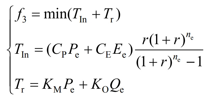
In the formula: TIn is the annual value of initial investment cost; Tr is the cost of operation and maintenance; CP and CE are the unit costs of energy storage power capacity and energy capacity, respectively; Pe and Qe respectively represent the power capacity of energy storage and the annual power generation; KM is the annual operating and maintenance cost coefficient per unit power of energy storage; KO is the annual operation and maintenance cost coefficient per unit of energy storage; R is the benchmark discount rate; Ne is the operating life of energy storage.
3.2 Constraints and Solution Methods
1) Energy storage constraints
Due to the fast response dynamic process of energy storage charging and discharging, in order to ensure the safe operation of energy storage, it is necessary to consider not only the rated power constraint but also the capacity constraint when constraining its charging and discharging power, namely:
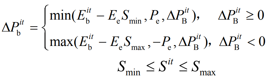
In the formula: ∀ i ∈ NB; NB is the total number of configured energy storage; Δ PBit Δ Pbit, Ebit, and Sit are the theoretical output, actual output, residual energy capacity, and SOC of energy storage i during cycle t.
2) Solution method
After using the improved multi-objective particle swarm optimization algorithm in Chapter 2 to obtain the Pareto solution set, the optimal solution is obtained using the technology for order preference by similarity to ideal solution (TOPSIS) method based on entropy weight. TOPSIS can fully utilize the information of the original data and use information entropy to obtain the weights of various indicators. Finally, the closeness of each scheme to the ideal scheme can be calculated as a criterion for evaluating the quality of the scheme.
By using equations (23) and (24) to calculate the information entropy and weight of each objective function, the subjectivity of the data can be effectively avoided. This method not only does not require specifying an objective function, but also does not require verification, making the operation relatively convenient and flexible.
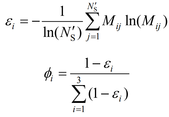
In the equation: ε I φ I is the information entropy and weight of the objective function i, respectively; Mij is the contribution of particle j to the objective function i, 0<Mij<1; NS’ represents the size of the final Pareto solution set for the population.
After calculating the distance between the particle and the negative ideal scheme and the positive ideal scheme, the comprehensive distance of the normalized particle j is finally determined, as shown below.
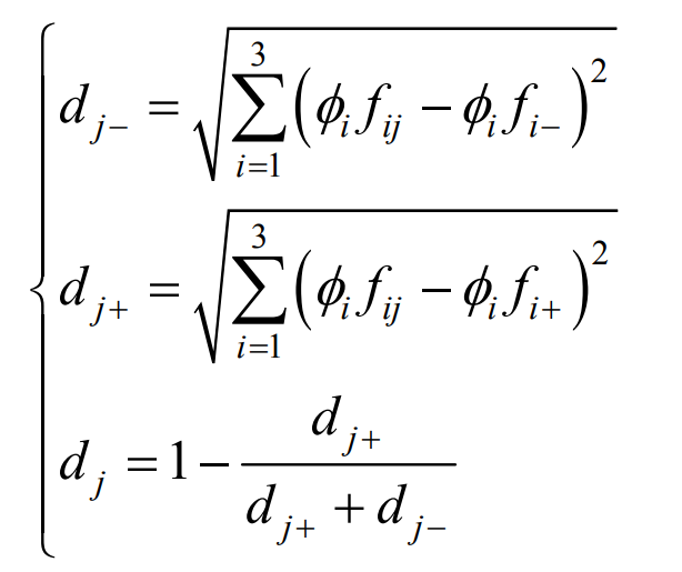
In the formula, dj is the comprehensive distance of particle j; Dj − and dj+are the distances from particle j to the negative ideal scheme and the positive ideal scheme, respectively; Fij is the normalized value of the objective function i of particle j; Fi − and fi+are the negative ideal values and positive ideal values of the normalized objective function i.
Each particle represents a solution, and the larger the overall distance, the smaller the distance between the solution and the positive ideal solution, resulting in a higher overall score for the solution. In order to improve the optimization efficiency of the multi-objective PSO algorithm, the comprehensive distance obtained by the TOPSIS method based on entropy weight is used as the standard method to determine the optimal position of individual particles and populations. In summary, the multi-objective solution process for energy storage capacity and location planning. Among them, various unit output models can be solved using equations (26) and (27), using YALMIP software on the MATLAB platform, and using the CPLEX solver for calculation and solution.
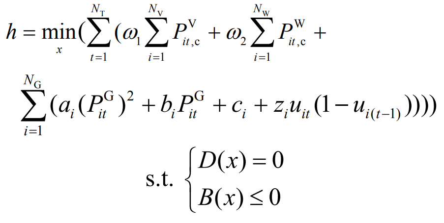
In the formula, PVit, c, PWit, c, and PGit respectively represent the amount of photovoltaic waste, wind power waste, and thermal power output; ω 1 ω 2 are punishment for abandoning light and abandoning wind; Ai, bi, and ci are fuel cost coefficients, respectively; Zi is the start-up cost; UIT is in the on/off state; NV, NW, and NG respectively refer to the number of photovoltaic power stations, wind farms, and thermal power units; D (x) contains power balance constraints in day ahead scheduling scheme x; B (x) includes constraints on the upper and lower limits of unit output, climbing rate, positive and negative rotating reserve capacity, startup and shutdown time, etc. in the day ahead scheduling scheme.
4.Analysis of multi-objective optimization examples for energy storage systems under high proportion of new energy
4.1 Basic data of calculation examples
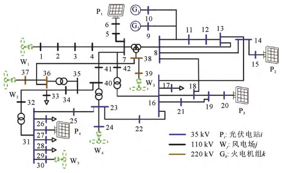
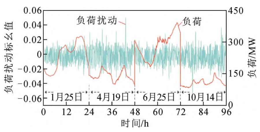
Conduct research based on the operation of a regional power grid in Anyang City in 2020. The power generation capacity of the region is 741 MW, with a maximum load of 410 MW, including 43 nodes, 2 thermal power units, 5 wind farms, and 4 photovoltaic power stations, making it a typical renewable energy center. This study used MATLAB to establish an actual simulation example of the regional power grid, and established a dynamic model shown in Figure A1 of Appendix A in MATLAB/Simulink. Table A2 in Appendix A shows the simulation parameters of energy storage in the regional power grid, including the technical and economic parameters of energy storage and the basic parameters of the dynamic model. The wiring diagram, typical daily load curve, and load disturbance of the example system are shown in Figures 6 and 7, respectively. Set the frequency modulation period to 24 hours × 4. The sampling interval is 60 seconds.
4.2 Analysis of simulation results
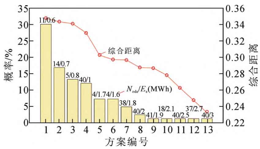
The proposed improved multi-objective PSO algorithm is used to solve experimental examples, obtain the probability distribution of energy storage configuration schemes in the decision space, and calculate the corresponding comprehensive distance of these schemes, as shown in Figure 8. As shown in Figure 9, in the energy storage configuration scheme, the smaller the capacity, the larger the corresponding comprehensive distance. This is because the variation amplitude of the energy storage cost index is greater than that of the grid vulnerability index and frequency fluctuation index, so it has a higher entropy weight. The energy storage cost is greatly affected by the energy storage capacity, and the optimal solution obtained is to configure the energy storage capacity Ee and node node as 0.6 MWh and 11, respectively. In addition, due to the use of the TOPSIS method based on entropy weight as the criterion for determining the optimal position of individual particles and populations, the larger the comprehensive distance of the scheme, the more times it appears in the optimization process.
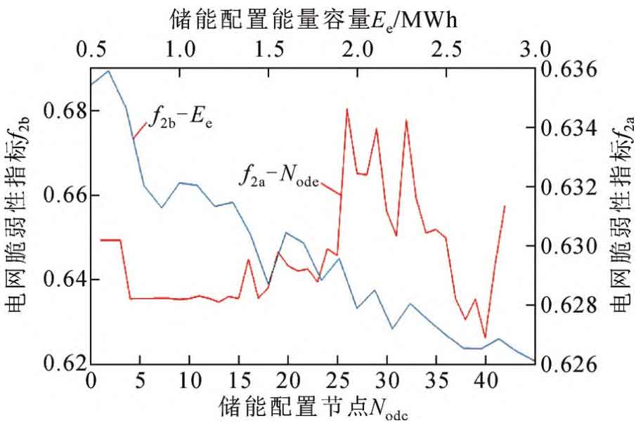
Considering the complex and even contradictory relationship between the objective functions proposed in this article, three boundary schemes have been retained as reference schemes for energy storage optimization configuration to meet practical engineering needs, as shown in Table 1. Among them, the negative ideal scheme represents the system parameters and budget before energy storage configuration, while the positive ideal scheme represents the most ideal value of various indicators. From Table 1, it can be seen that the boundary scheme 1 and 2 for energy storage are the same, with a capacity of 3 MWh and a node configuration of 40, respectively. By configuring the energy storage capacity to 3MWh and calculating the vulnerability indicators of the power grid at different energy storage configuration positions (as shown in Figure 9), the optimal node can be obtained as 40; By configuring the energy storage location as node 40 and calculating the vulnerability indicators of the power grid under different energy storage capacities (as shown in Figure 10), the optimal capacity can be obtained as 3 MWh. These results demonstrate the effectiveness of the method proposed in this paper. It is worth mentioning that the location selection of energy storage mainly considers its ability to improve voltage quality. As shown in Figure 10, the ability of energy storage to improve voltage quality is roughly positively correlated with the size of its configuration capacity.
| Programme | Node | Ee /MWh | Pe /MW | f1/Hz | f2 | f3/Ten thousand yuan |
| Negative ideal scheme | 0.0557 | 0.689 | 100 | |||
| Positive ideal solution | 0 | 0 | 0 | |||
| Optimal solution 1 | 11 | 0.6 | 1.12 | 0.0507 | 0.635 | 25.6 |
| Boundary Scheme 1 | 40 | 3 | 1.28 | 0.0491 | 0.626 | 56.5 |
| Boundary Scheme 2 | 40 | 3 | 1.28 | 0.0491 | 0.626 | 56.5 |
| Boundary Scheme 3 | 11 | 0.6 | 1.12 | 0.0507 | 0.635 | 25.6 |
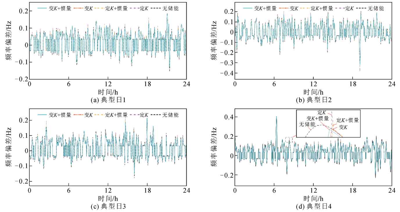
The effect of energy storage participating in frequency modulation using the optimal energy storage configuration and typical daily load disturbance is shown in Figure 10. Figure 10 shows the variation of frequency deviation under different control methods. It can be seen from the figure that the energy storage with variable K and inertia control has the best effect in frequency modulation. Due to the capacity limitation of energy storage, the constant K control may cause a secondary disturbance in frequency when the energy storage output suddenly stops. However, since the energy storage output changes in an S-shape with SOC, the variable K control is not affected by this issue. Finally, using the frequency fluctuation index shown in equation (17), the results obtained by using different control methods for energy storage are shown in Table 2. From Table 2, it can be seen that after parameter optimization, the non-linear variable K and inertia energy storage participate in the optimal performance of frequency modulation control.
| Control method | Nonlinear variable K+inertia | Nonlinear variable K | Fixed K+inertia | Fixed K | No energy storage |
| Frequency fluctuation index/Hz | 0.0507 | 0.0511 | 0.0513 | 0.0517 | 0.0557 |
5.Conclusion
The multi-objective optimization problem of energy storage systems with frequency modulation control under high proportion of new energy was studied. Research analysis shows that as the proportion of new energy continues to increase, the primary frequency regulation capability and system inertia of the power grid are becoming increasingly insufficient. Based on the analysis of actual examples, the following conclusions are drawn:
1) The energy storage control strategy based on nonlinear variable K coefficient can effectively enhance the primary frequency regulation control ability of energy storage participating in high proportion new energy systems. After parameter optimization, this method has better frequency modulation effect compared to other control methods.
2) The improved multi-objective PSO algorithm is used to solve the multi-objective optimization model for energy storage capacity and location selection, which can achieve comprehensive optimization of improving energy storage auxiliary frequency regulation ability, power grid operation safety, and energy storage configuration economy.
3) The TOPSIS method based on entropy weight is used to sort the obtained Pareto solution set to obtain a relatively compromise optimization plan, which can effectively balance the optimization configuration of energy storage system capacity and location, and achieve the solution of the optimal plan.