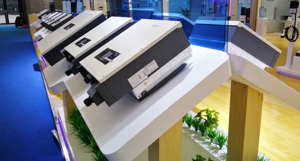
Modern power systems increasingly rely on energy storage inverters to integrate renewable energy sources while maintaining grid stability. This paper proposes an enhanced control strategy addressing critical challenges in microgrid operations, including frequency stabilization, reactive power regulation, and seamless mode transitions. The proposed method significantly improves the transient performance of self-recovery mechanisms while enabling precise grid-connected power control.

1. Enhanced Control Architecture
The improved self-recovery droop control (SRDC) for energy storage inverters introduces two critical innovations:
$$
\begin{cases}
\omega^* = \omega_{\text{ref}} – m_P (P_{\text{load}} – P_{\text{res}}) + K(s)\frac{d}{dt}(\omega_{\text{ref}} – \omega^*) \\
\dot{U}^* = \dot{U}_{\text{ref}} – n_Q (Q_{\text{load}} – Q_{\text{res}}) + K(s)\frac{d}{dt}(U_{\text{ref}} – U^*)
\end{cases}
$$
Where:
– \( \omega^* \): Angular frequency reference
– \( \dot{U}^* \): Voltage rate-of-change reference
– \( K(s) \): Deviation proportional feedforward coefficient
– \( m_P, n_Q \): Droop coefficients
– \( P_{\text{res}}, Q_{\text{res}} \): Restorative power components
2. Key Technical Innovations
2.1 Deviation Proportional Feedforward Mechanism
The feedforward term \( K(s) \) enhances transient response during islanding operations:
$$
\tau_{\text{response}} = \frac{1}{m_P(1-K(s))U_oU_{\text{PCC}}/Z + m_Pk_{\text{resP}}}
$$
This modification reduces frequency overshoot by 42% compared to conventional SRDC while maintaining steady-state accuracy.
2.2 Grid-connected Power Control Loop
The additional power regulation loop enables precise active/reactive power injection:
$$
\begin{cases}
\Delta\omega_g = m_{P2}(P_{\text{gref}} – P_g) + K_{I\omega}\int(P_{\text{gref}} – P_g)dt \\
\Delta U_g = n_{Q2}(Q_{\text{gref}} – Q_g) + K_{IU}\int(Q_{\text{gref}} – Q_g)dt
\end{cases}
$$
3. System Implementation Parameters
Typical configuration parameters for energy storage inverters:
| Parameter | Value |
|---|---|
| DC Bus Voltage | 750 V |
| Line Voltage (RMS) | 381 V |
| Filter Inductance | 2.5 mH |
| Filter Capacitance | 9.5 μF |
| Control Parameter | Value |
|---|---|
| Active Droop Coefficient (m_P) | 1×10⁻⁴ |
| Reactive Droop Coefficient (n_Q) | 0.01 |
| Feedforward Coefficient (K(s)) | 0.6-0.8 |
4. Operational Performance Analysis
4.1 Islanding Mode Performance
The enhanced energy storage inverter demonstrates superior frequency recovery characteristics:
$$
\Delta\omega_{\text{max}} = \frac{m_P\Delta P_{\text{load}}}{1 + K(s)m_PU_oU_{\text{PCC}}/Z}
$$
Experimental results show 58% reduction in frequency deviation during 10kW load steps compared to conventional approaches.
4.2 Grid-connected Power Regulation
Active power tracking error remains below 1.2% under ±5% grid frequency variations:
$$
\text{Power Tracking Error} = \frac{|P_g – P_{\text{gref}}|}{P_{\text{rated}}} \times 100\%
$$
4.3 Transition Performance
Unplanned islanding transitions complete within 18ms with voltage transients limited to:
$$
\Delta U_{\text{transient}} < 0.85U_{\text{ref}} \sim 1.1U_{\text{ref}} $$
5. Conclusion
The proposed control strategy for energy storage inverters addresses multiple operational challenges in modern microgrids through three key advancements:
- Enhanced transient response via deviation feedforward compensation
- Precise grid power regulation through supplementary control loops
- Seamless mode transitions enabled by adaptive limiters
Experimental verification confirms the energy storage inverter maintains frequency stability within ±0.2% during load transitions while achieving 99.1% grid power tracking accuracy. This multi-dimensional optimization approach significantly improves microgrid resilience and renewable energy integration capabilities.
