
With the continuous development of photovoltaic grid connected power generation, its location has gradually expanded from the northwest desert to the interior of cities. Due to the complex structure of urban buildings, the environmental temperature and light intensity of photovoltaic modules are also different. Therefore, traditional solar grid connected inverters cannot meet the needs of urban photovoltaic grid connected power generation systems. Therefore, a multi branch solar grid connected inverter structure is adopted to solve the problem of independent maximum power point tracking Power mismatch and other issues.
The isolated multi branch solar grid connected inverter integrates a multi branch photovoltaic structure, consisting of a high-frequency solar inverter, a high-frequency isolation transformer, a rectifier, a DC bus, a power frequency solar inverter, and an output filter. The front stage adopts a high-frequency chain structure multi branch design, while the solar grid connected inverter is arranged in a centralized manner. Its circuit structure is shown in Figure 1.
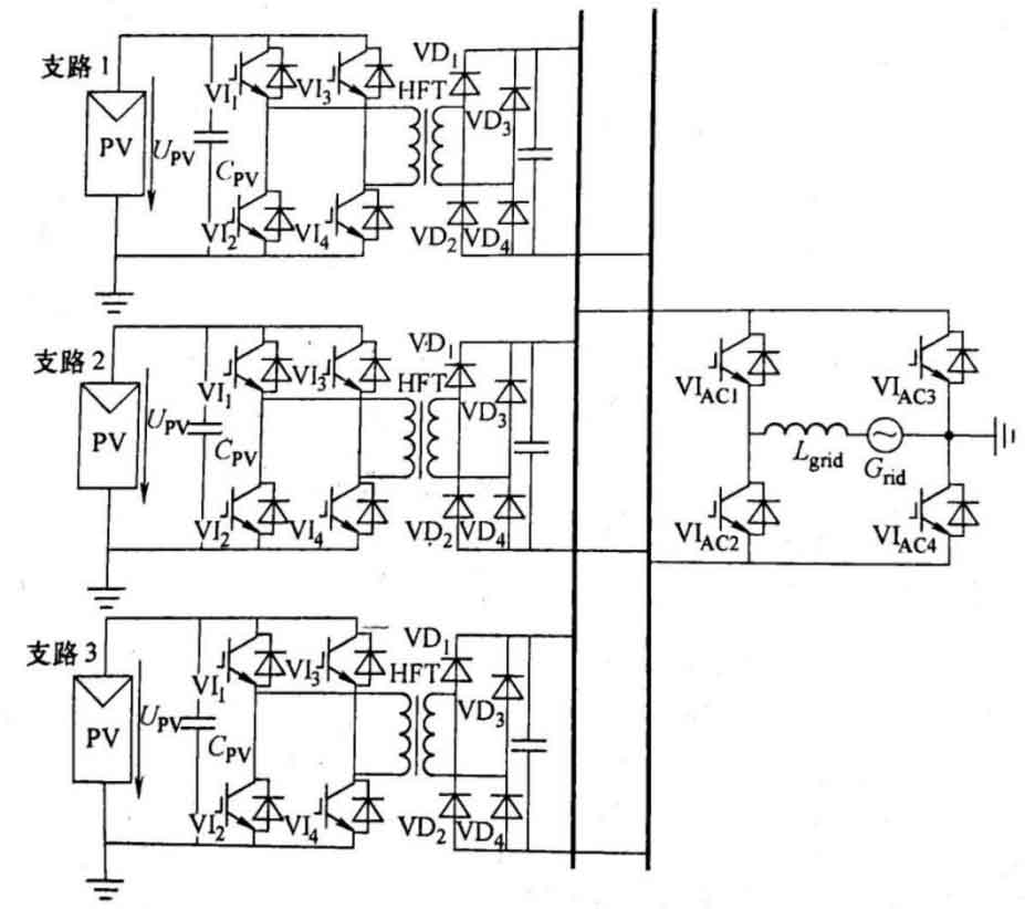
For each branch, the maximum power point tracking and DC voltage output control are achieved by the high-frequency solar inverter of that branch. The subsequent stage of the power frequency solar grid connected inverter achieves energy transmission through the control strategy of AC current inner loop and DC voltage outer loop. The solar energy inverter has the following advantages:
(1) Each branch independently tracks the maximum power point without any current mismatch issues.
(2) To achieve electrical isolation, the transformer is lightweight due to the use of high-frequency solar inverters.
(3) The circuit flexibility is extremely high, and changes in the number of photovoltaic array groups connected to the DC bus will not affect other arrays.
(4) Suitable for integrated photovoltaic building methods.
Of course, it also has the following drawbacks:
(1) After three levels of power conversion, the system has low power generation efficiency and high power generation costs.
(2) The operating frequency of the system is high frequency, and switch losses cannot be ignored.
(3) The system has poor impact resistance performance.
To improve system efficiency, further reduce system volume and power generation costs, non isolated multi branch solar grid connected inverters can be used. Each branch of the non isolated solar grid connected inverter is equipped with a set of DC/DC converters to complete voltage conversion and maximum power point tracking function. The solar grid connected inverter is also in a centralized configuration, and its circuit structure is shown in Figure 2.
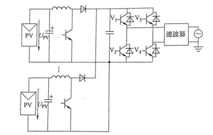
Due to the removal of high-frequency solar inverters, high-frequency transformers, and rectifier circuits, non isolated multi branch solar grid connected inverters have the advantages of high maximum power point tracking efficiency, good scalability, and high flexibility.
With the development of power technology, the requirements for voltage change rate, harmonic content, switching loss and other issues of solar inverters are also increasing. To reduce the existence of such problems, multi-level solar inverters are often used for grid connected inversion. However, traditional multi-level solar inverters require significantly more components as the number of levels increases, and the complexity of control strategies also greatly increases, The cascaded multi-level solar grid connected inverter can reduce electrical components and control strategy complexity. Its typical structure is a two unit cascaded five level solar inverter, and its circuit structure is shown in Figure 3.
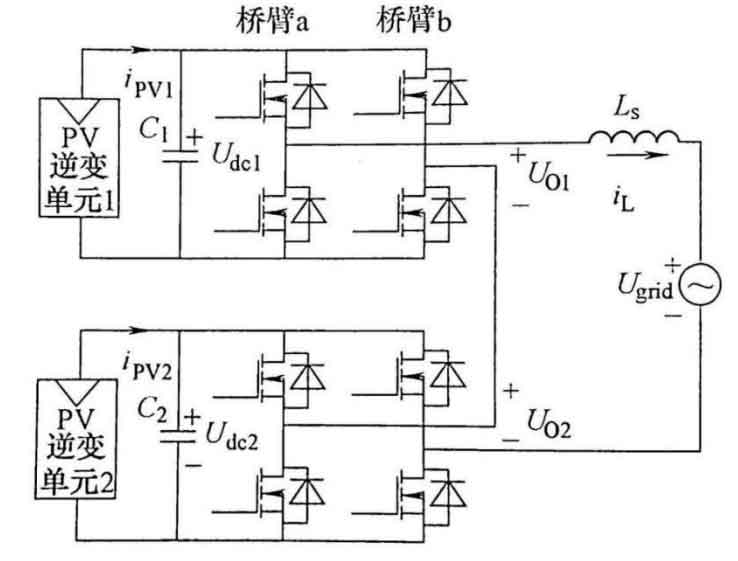
The cascaded solar grid connected inverter combines the DC voltage generated by each set of DC/AC converters to form a multi-level voltage waveform to meet the requirements of voltage change rate and harmonic content.
The modulation methods of cascaded multi-level solar grid connected inverters are mainly divided into three categories:
(1) The stepped wave modulation method and the specific harmonic elimination pulse width modulation method (SHEPWN), but their inverter waveform is related to the number of cascades, and only when there are more cascades, the inverter waveform is better.
(2) Space vector modulation method is mainly used for three-phase solar inverters below five levels, which is not conducive to expanding the number of cascades.
(3) The SPWM method can be divided into carrier stacking method and carrier phase shifting method. The carrier stacking method has certain difficulties in achieving independent maximum power point tracking, while the carrier phase shifting method can obtain the corresponding number of cascaded carrier signals through carrier phase shifting, which can solve the problem of maximum power point tracking for each group of photovoltaic modules.