
In the context of global carbon neutrality and peak carbon emissions initiatives, the transition towards green, environmentally friendly, and low-carbon lifestyles has become a paramount direction across industries. Energy conservation and consumption reduction are central to this shift. Within this framework, energy storage technology is recognized as a critical component of the power grid’s operational chain, encompassing generation, transmission, distribution, consumption, and storage. It serves as a fundamental pillar for the development of new energy sources and is essential for constructing a modern energy industry system characterized by cleanliness, low carbon emissions, safety, and high efficiency. The battery energy storage system, as a core device in renewable energy storage, has seen demand surge to a point of supply shortage. To enhance production output, there is an urgent need to upgrade discrete production modes and improve the automation level of manufacturing equipment.
Currently, in the production process of battery energy storage systems, several challenges persist. These include performance degradation or failure of battery modules due to collisions or self-discharge during transportation and storage of individual cells, welding defects such as blowholes and cold welds caused by unstable welding quality, and inefficiencies in discrete production modes, such as high labor intensity, process disorder, and low productivity. To address these shortcomings, we have designed a modular assembly and testing production line for battery energy storage systems. This production line enables fully automated assembly-line operations from cell to finished module testing, resolving pain points like manual handling, process confusion, and quality instability. It enhances production efficiency, reduces costs, and is adaptable to large-scale automated production.
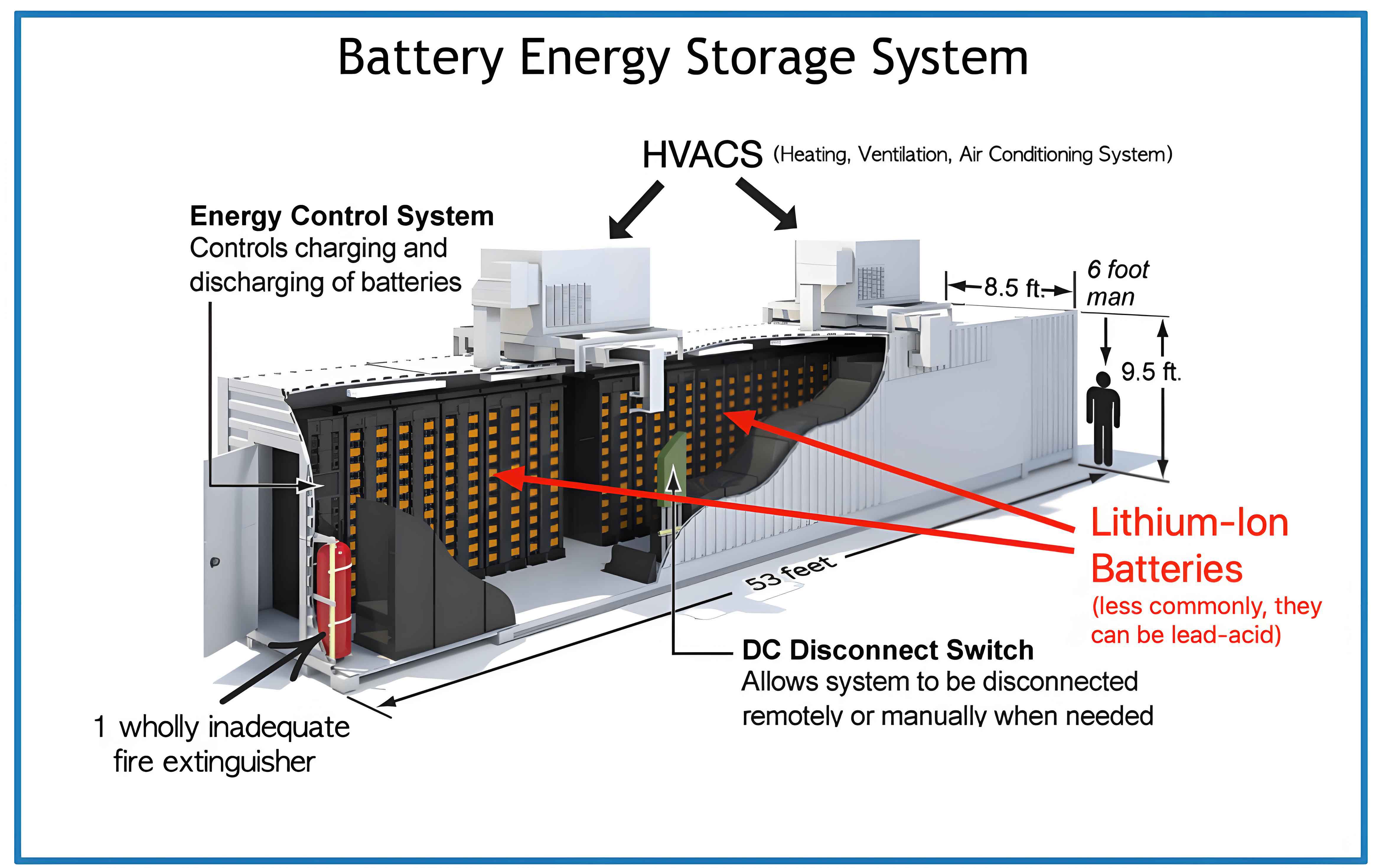
The battery energy storage system module primarily consists of a housing, cover plate, front end plate, battery cells, fin separators, a CCS (Cell Contact System) harness assembly, and a Battery Management Unit (BMU). The assembly process involves alternately stacking cells and fin separators within the housing, installing the CCS harness assembly onto the cells, and then welding the busbars of the CCS harness to the cell poles to form electrical circuits. Subsequently, components such as the BMU and terminal blocks are assembled. After assembly, electrical performance tests, including voltage, internal resistance, insulation impedance, and withstand voltage tests, are conducted on the module.
The main production工艺流程 and key processes include automated cell feeding, cell performance testing and screening, cell stacking into the housing, module pressing and monitoring, pole positioning, polarity detection, pole cleaning, busbar welding, post-weld inspection, insulation testing, voltage and internal resistance testing, communication testing, and final inspection and下线. Key process controls are implemented as follows:
- Cell Testing: This involves detecting and screening individual cells for voltage, internal resistance, and voltage differential to prevent non-conforming products from entering the production flow.
- Pole Cleaning: Removing oxide layers and contaminants from the cell poles to prevent hydrogen generation under high temperatures during welding, thereby reducing welding blowholes.
- Busbar Welding and Inspection: Utilizing composite laser welding technology, where an outer ring laser provides low-temperature preheating and an inner ring laser performs deep penetration welding, to minimize defects like spatter, blowholes, and cold welds.
- Performance Testing: Conducting comprehensive electrical performance tests on the module, including voltage, internal resistance, insulation impedance, and withstand voltage, to ensure product reliability.
The production line for battery energy storage systems employs a modular design, primarily comprising four units: the Cell Detection Unit, Module Pressing Unit, Module Welding Unit, and Module Testing Unit. These units are integrated via a double-speed chain conveyor system, connecting workstations for cell detection, module pressing, module welding, and electrical performance testing into a continuous flow line. All workstations operate at the same cycle time, enabling single-piece flow and achieving fully automated production from cells to finished module testing.
Cell Detection Unit Design: This unit includes a cell feeding station, an OCV (Open Circuit Voltage) detection station, and a module stacking station. The cell feeding station uses a robotic arm to pick cells from storage racks and place them into slots on the conveyor belt of the OCV detection station. The OCV tester, mounted on a three-axis gantry, lowers probes onto the positive and negative poles of each cell to form a circuit, measuring voltage, internal resistance, and voltage differential. The data is uploaded and compared with原始 data in the central control server to assess cell stability. Qualified cells proceed via conveyor to the module stacking station, where operators perform visual inspections and manually stack cells into modules on a stacking trolley. Safety measures, such as protective fencing and infrared sensors, ensure human-machine separation during operation.
Module Pressing Unit Design: This unit consists of a module loading station, polarity detection station, and module pressing station. A gantry crane transfers the module from a transport cart to a pallet on the conveyor, which then moves it to the polarity detection station. A three-axis CCD camera system identifies the positive and negative poles of each cell, uploading polarity data to the central server for verification of correct stacking orientation. The module pressing station compresses the module to its design dimensions and installs end plates for fixation, controlling cell expansion during operation. Pressure sensors monitor the force applied during pressing, with alarms set for极限 values to prevent cell damage.
Module Welding Unit Design: This unit includes a pole positioning station, pole cleaning station, CCS harness installation station, busbar laser welding station, post-weld inspection station, and NG (Non-Good) offloading station. The pole positioning station uses a three-axis CCD ranging system to map the coordinates of the module and cell poles, sharing this data with subsequent stations for precise cleaning and welding. The pole cleaning station employs laser ablation to remove oxide layers and contaminants from the poles based on the shared coordinates. The CCS harness installation station involves manual placement and fixation of the harness assembly. The laser welding station then welds the busbars to the cell poles using composite laser technology. A high-power negative pressure dust removal system extracts smoke and spatter during welding to prevent debris from entering the module. Post-weld inspection checks each weld for defects like cold welds, fractures, blowholes, or misses, with non-conforming modules diverted to the NG offloading station for rework.
Module Testing Unit Design: This unit comprises a BMU installation station, EOL (End of Line) testing station, communication testing station, and final inspection and offloading station. At the BMU installation station, components like the BMU and terminal busbars are installed, with torque monitoring for fasteners. The EOL testing station conducts electrical performance tests, including voltage, internal resistance, insulation impedance, and withstand voltage. The communication testing station measures individual cell voltages and temperatures, analyzing differentials for abnormalities. The final inspection station performs last checks, applies合格 labels, and offloads finished modules.
MES Information System Design: The system includes a monitoring host, terminals at each workstation, and display screens. Operators scan codes to input production data at terminals, which is processed by the host and displayed for real-time tracking and coordination. Functions include process management, data acquisition and retrieval, and electronic dashboards. Process management involves calling up assembly instructions and monitoring equipment status based on production configurations. Data acquisition collects test data, key工艺 parameters, personnel information, equipment status, and fault records. Electronic dashboards display metrics such as planned vs. actual production, yield rates, and equipment status, enabling transparent production management.
To validate the production line, we conducted comprehensive performance tests. The integration of units via the double-speed chain enables continuous flow, with a modular design allowing each unit to operate independently in case of faults, preventing全线 downtime. In practical production tests, the line can weld 8 cells per minute, achieving a cycle time of approximately 3 minutes for a 24-cell module. This represents a threefold increase in production efficiency compared to single-station modes and reduces the required operators by 9. Below, we summarize key performance metrics in a table:
| Metric | Before Implementation | After Implementation | Improvement |
|---|---|---|---|
| Production Cycle Time (per module) | ~9 minutes | ~3 minutes | 66.7% reduction |
| Number of Operators | 12 | 3 | 75% reduction |
| Product合格 Rate | ~98.5% | ≥99.88% | ≥1.38% increase |
| Line Availability | Low due to discrete stops | High due to modular independence | Significant enhancement |
Key process性能 tests focused on pole laser cleaning and module laser welding. For pole cleaning, laser ablation removes contaminants and oxide layers, reducing hydrogen sources during welding. We evaluated this via cross-sectional metallographic analysis and tensile testing. The cleaning effectiveness can be quantified by the reduction in porosity and improvement in weld strength. The tensile strength after cleaning increased by approximately 8.7%, as shown in the table below:
| Sample Condition | Tensile Strength Sample 1 (kN) | Tensile Strength Sample 2 (kN) | Tensile Strength Sample 3 (kN) | Average Tensile Strength (kN) |
|---|---|---|---|---|
| Uncleaned | 2.996 | 2.895 | 2.766 | 2.885 |
| Laser Cleaned | 3.108 | 3.127 | 3.146 | 3.137 |
The improvement is attributed to minimized porosity, as hydrogen entrapment is reduced. The porosity percentage can be modeled using the equation:
$$ P = \frac{V_{\text{pores}}}{V_{\text{weld}}} \times 100\% $$
where \( P \) is the porosity percentage, \( V_{\text{pores}} \) is the volume of pores, and \( V_{\text{weld}} \) is the total weld volume. Laser cleaning reduces \( V_{\text{pores}} \), leading to lower \( P \).
For module laser welding, composite laser technology is employed. The welding quality depends on parameters such as effective熔 depth, effective熔 width, and central trajectory. The welding area, which determines current-carrying capacity, is calculated using the formula for an annular ring:
$$ S = \frac{\pi (D^2 – d^2)}{4} $$
where \( S \) is the welding area, \( D \) is the outer diameter of the weld trajectory, and \( d \) is the inner diameter. Given a cell pole diameter of 15 mm, we set \( D = 12 \, \text{mm} \) and \( d = 10 \, \text{mm} \), yielding:
$$ S = \frac{\pi (12^2 – 10^2)}{4} = \frac{\pi (144 – 100)}{4} = \frac{\pi \times 44}{4} = 11\pi \approx 34.56 \, \text{mm}^2 $$
This exceeds the minimum required area of 32 mm² for a discharge current of 164 A, ensuring sufficient载流 capacity. The effective熔 width is \( D – d = 2 \, \text{mm} \), and the central trajectory is \( \frac{D + d}{2} = 11 \, \text{mm} \).
Tensile tests indicate that with an effective熔 depth of ≥1.1 mm, the weld strength surpasses the base material’s tensile strength, as failure occurs in the pole rather than the weld. This demonstrates reliable welding performance. The relationship between weld strength and熔 depth can be expressed as:
$$ F_{\text{tensile}} = k \cdot A_{\text{bond}} \cdot \sigma_{\text{weld}} $$
where \( F_{\text{tensile}} \) is the tensile force, \( k \) is a geometric factor, \( A_{\text{bond}} \) is the bonded area, and \( \sigma_{\text{weld}} \) is the weld material strength. For our parameters, \( A_{\text{bond}} \) is proportional to the熔 depth and width.
Over three months of operation, the product合格 rate has consistently exceeded 99.88%, addressing issues like blowholes and cold welds. The automation of the production line for battery energy storage systems has resolved pain points such as manual handling, material waiting, space占用, and process disorder, reducing labor intensity and enhancing efficiency. The modular design allows flexibility and fault tolerance, while key technologies like laser cleaning and composite welding ensure high-quality outputs. This approach offers significant economic benefits and provides a scalable solution for automated production of battery energy storage systems, with broad application prospects in the renewable energy sector.
In conclusion, our modular production line for battery energy storage systems integrates advanced automation and process control, achieving substantial improvements in productivity and quality. The use of formulas and tables herein summarizes critical parameters and outcomes, underscoring the technical rigor behind the design. As demand for battery energy storage systems continues to grow, such innovative manufacturing solutions will play a pivotal role in meeting global energy sustainability goals.