
In many remote mountainous regions and off-grid areas worldwide, ensuring reliable electricity access for residents remains a critical challenge. The development of renewable energy technologies, particularly solar power, combined with advancements in energy storage systems, has enabled the creation of small-scale, modular microgrids. These systems offer single-point connectivity, multi-mode operation, and embody the principles of smart grids. This study focuses on designing and testing a modular off-grid solar system to address energy shortages in areas like isolated islands and underserved communities. By leveraging abundant solar resources and integrating battery storage, this off-grid solar system provides a sustainable solution for electricity needs, supporting economic development and environmental sustainability.
The core of this research involves a comprehensive design and experimental validation of a modular off-grid solar system. The system is composed of photovoltaic (PV) modules, lightning protection combiner boxes, off-grid energy storage inverters, battery banks, an upper-level monitoring system, and an optional diesel generator. The diesel generator serves as a backup power source, while solar energy is the primary contributor. This configuration ensures reliability and adaptability to varying energy demands, making it ideal for decentralized applications.
To determine the system’s capacity, we analyzed the energy consumption of a typical island living pod, as summarized in Table 1. By staggering the use of high-power appliances and operating desalination systems during peak sunlight hours, the daily energy consumption was estimated at 23 kWh. Assuming an effective daily sunlight duration of 4 hours and an overall system efficiency of 0.6, the required PV module capacity can be calculated using the formula:
$$ P_{pv} = \frac{E_{daily}}{H_{sun} \times \eta} $$
where \( P_{pv} \) is the PV capacity in kW, \( E_{daily} \) is the daily energy consumption in kWh, \( H_{sun} \) is the daily sunlight hours, and \( \eta \) is the system efficiency. Substituting the values:
$$ P_{pv} = \frac{23}{4 \times 0.6} = 9.58 \, \text{kW} $$
For the battery storage, considering a depth of discharge (DOD) of 50% and one day of autonomy during cloudy weather, the energy storage capacity is estimated as:
$$ E_{bat} = \frac{E_{daily}}{DOD} $$
where \( E_{bat} \) is the battery energy capacity in kWh. Thus:
$$ E_{bat} = \frac{23}{0.5} = 46 \, \text{kWh} $$
This calculation ensures that the off-grid solar system can sustain power supply during intermittent solar availability.
| Appliance | Power Rating (W) | Daily Usage (h) | Energy Consumption (kWh) |
|---|---|---|---|
| Lighting | 200 | 6 | 1.2 |
| Refrigeration | 150 | 24 | 3.6 |
| Water Pump | 500 | 2 | 1.0 |
| Desalination Unit | 3000 | 5 | 15.0 |
| Communication Devices | 100 | 4 | 0.4 |
| Miscellaneous | 200 | 2 | 0.4 |
| Total | – | – | 21.6 (approx. 23 kWh) |
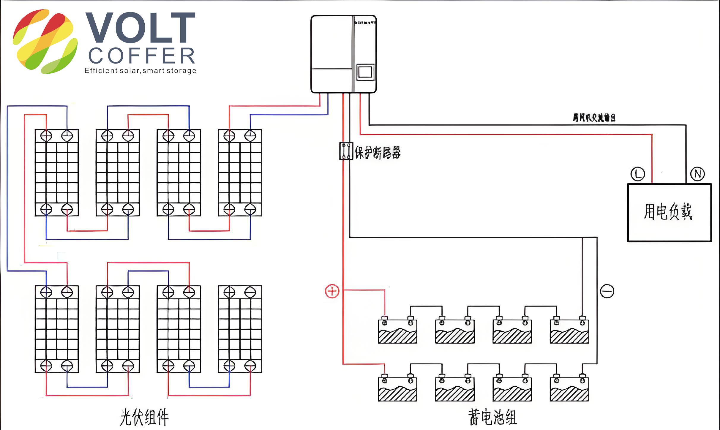
The system architecture, illustrated in Figure 1, incorporates three parallel off-grid energy storage inverters connected to a common AC bus. An automatic transfer switch (ATS) controls the diesel generator’s operation, enabling seamless power switching. This modular design allows for scalability and redundancy, enhancing the system’s robustness for various off-grid solar system applications.
System Components and Configuration
The off-grid solar system’s performance hinges on the careful selection of components. The heart of the system is the off-grid energy storage inverter, which manages power flow between the PV modules, batteries, and loads. We selected a model with maximum power point tracking (MPPT) capabilities, battery charge/discharge management, and adaptive energy utilization based on solar irradiance. Key parameters are listed in Table 2.
| Parameter | Value |
|---|---|
| Model | GMDE-105K48P |
| Rated Power | 10 kW |
| PV Input Voltage Range | 100-500 V DC |
| Battery Voltage | 48 V DC |
| AC Output Voltage | 230 V ±5% |
| Frequency | 50 Hz ±0.5% |
| Efficiency | >95% |
| MPPT Efficiency |
For the PV modules, we opted for polycrystalline silicon panels due to their cost-effectiveness and adequate efficiency. For instance, a 260Wp polycrystalline module was chosen, with specifications in Table 3. The array configuration consisted of 3 strings in series and 4 in parallel, connected via a 4-in-1-out lightning protection combiner box to optimize input to the inverters.
| Parameter | Value |
|---|---|
| Model | Yingli 260Wp |
| Rated Power | 260 W |
| Open Circuit Voltage | 38.2 V |
| Short Circuit Current | 8.9 A |
| Maximum Power Voltage | 30.8 V |
| Maximum Power Current | 8.4 A |
| Efficiency | 15.8% |
The battery bank utilized maintenance-free gel batteries, selected for their longevity and suitability for energy storage applications. To minimize imbalance issues, we limited parallel connections to three groups, with a total capacity of 14.4 kWh (48V system with 100Ah batteries). The battery sizing considered economic constraints, though ideally, autonomy could be extended to 3-5 days with higher budgets. The general formula for battery capacity in an off-grid solar system is:
$$ C_{bat} = \frac{E_{daily} \times D_{autonomy}}{DOD \times V_{sys}} $$
where \( C_{bat} \) is the battery capacity in Ah, \( D_{autonomy} \) is the days of autonomy, \( DOD \) is the depth of discharge, and \( V_{sys} \) is the system voltage. For our case with one day autonomy:
$$ C_{bat} = \frac{23 \times 1}{0.5 \times 48} \approx 96 \, \text{Ah} $$
Thus, a 100Ah battery bank was appropriate, but modular expansion is feasible for larger needs.
Experimental Validation and Results
To validate the off-grid solar system’s reliability, we conducted single-unit and parallel operation tests. The single-unit test involved a setup with 12 PV modules (3 series × 4 parallel), a combiner box, one inverter, and a battery bank. Loads of approximately 1900W and 2100W were applied over 7-8 hours, with solar irradiance measured using a light meter and inverter data logged via RS485 communication.
For the 1900W load test, results showed that the system maintained stable operation. The average solar irradiance curve indicated about 4 hours of effective sunlight (≥700 W/m²), aligning with theoretical assumptions. The PV input voltage and current varied with load and irradiance, while the battery voltage fluctuated between 48V and 49V, with state of charge (SOC) around 75-80% post-test. The AC output remained steady at 230V and 50Hz. The battery charge/discharge current profile demonstrated the inverter’s operational modes: discharging during low solar input and charging during excess generation. The power balance can be expressed as:
$$ P_{pv} + P_{bat} = P_{load} + P_{loss} $$
where \( P_{pv} \) is PV power, \( P_{bat} \) is battery power (positive for discharge, negative for charge), \( P_{load} \) is load power, and \( P_{loss} \) represents system losses. During testing, this balance was maintained effectively.
In the 2100W load test, irradiance was more sustained, with 5.5 hours of effective sunlight. The MPPT functionality ensured optimal PV utilization, reducing battery dependency. The output voltage and frequency were stable, confirming the system’s robustness for continuous operation.
For parallel testing, three inverters were connected in parallel with a shared battery bank and PV array (9 modules in 3 series × 3 parallel). A 1400W load was applied for nearly 7 hours. Data from the master (#014) and slave inverters (#007, #008) showed balanced power sharing and minimal voltage deviations. The PV input currents were slightly higher for the master inverter, indicating efficient MPPT tracking. The total output power and battery charging currents affirmed the system’s scalability and stability in modular configurations. The parallel operation efficiency can be modeled as:
$$ \eta_{parallel} = \frac{\sum P_{out}}{\sum P_{in}} $$
where \( \eta_{parallel} \) is the overall efficiency, \( P_{out} \) is output power per inverter, and \( P_{in} \) is input power. In our tests, this efficiency exceeded 90%, with even power distribution among units.
| Parameter | 1900W Load Test | 2100W Load Test |
|---|---|---|
| Effective Sunlight Hours | 4 h | 5.5 h |
| Battery SOC Change | ~5% decrease | Minimal change |
| PV Voltage Range | 90-120 V | 95-125 V |
| AC Output Stability | 230V ±2%, 50Hz ±0.5% | 230V ±1%, 50Hz ±0.5% |
These experiments demonstrate that the modular off-grid solar system can reliably meet energy demands in off-grid scenarios. The system’s flexibility allows for incremental expansion by adding more modules, making it cost-effective for varying power requirements. Moreover, the integration of smart inverters with ATS controls enhances resilience, particularly in regions with unreliable grid access.
Conclusion and Future Implications
The development and testing of this modular off-grid solar system highlight its potential to revolutionize energy access in remote areas. By combining solar generation with battery storage, the system offers a sustainable and scalable solution. The single-unit and parallel tests confirm its stability, efficiency, and adaptability under different load conditions. Key advantages include low installation costs, ease of assembly, and the ability to customize capacity based on user needs.
Future work could focus on optimizing battery technologies for longer autonomy, integrating hybrid renewable sources like wind, and implementing advanced energy management algorithms. As off-grid solar systems evolve, they will play a crucial role in achieving global energy equity and supporting sustainable development in underserved communities. This research underscores the importance of modular designs in making clean energy accessible worldwide.