After the battery energy storage system is connected to MMC, its SOC balance and sub module capacitor voltage balance are mutually constrained and influenced. Therefore, this chapter first defines the concept of sub module power imbalance, evaluates the balancing ability of sub modules using the allowable range of imbalance in the system, and serves as the design basis for SOC balancing controller parameters. Then, the submodule equalization ability of two commonly used control strategies, capacitor voltage closed-loop equalization control and sorting equalization control, was evaluated. On this basis, an optimized balancing control strategy based on capacitor voltage closed-loop is proposed to improve the balancing ability of sub modules. Finally, the analysis results and the effectiveness of the control strategy in this chapter were verified through simulation and experiments.
1. Evaluation method for balancing ability of sub modules
After integrating the battery energy storage system in MMC, the power transmission of sub modules within the same bridge arm is shown in Figure 1. The power of each submodule consists of two parts, one is the MMC side power Pji, which is determined by the output voltage uji of the submodule and the bridge arm current ij; The other part is the battery side power Pbji, which is determined by the balance control between the bridge arm battery power Pbj and SOC. According to the SOC control structure, the battery power of each submodule (with discharge as positive) is:

In the formula, SOCji is the sub module SOC, and SOCj is the average SOC of the bridge arm; K3 is the parameter of the submodule SOC equalization controller. The larger K3, the faster the SOC equalization speed, and the greater the power difference between submodules. The degree to which the power of the submodule battery deviates from the average battery power of the bridge arm can be defined as the unevenness of the submodule power λ Ji, to describe the power difference between submodules:
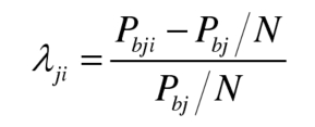
When using this definition, regardless of whether the battery is in a charging or discharging state, λ Ji>0 indicates that the sub module battery power is greater than the average battery power of the bridge arm, λ Ji<0 indicates that the battery power is less than the average battery power of the bridge arm; Specially, λ When ji=-1, the battery power of the submodule is 0, which can also indicate that there is no battery energy storage unit in the submodule, or that the battery energy storage unit is cut off due to a fault in these special working conditions; When λ When ji<-1, the power of the submodule battery is opposite to the average power direction of the bridge arm battery, and there are charging and discharging battery units inside the bridge arm. To avoid this situation, the power imbalance of the submodule can be limited to λ Ji ≥ -1.
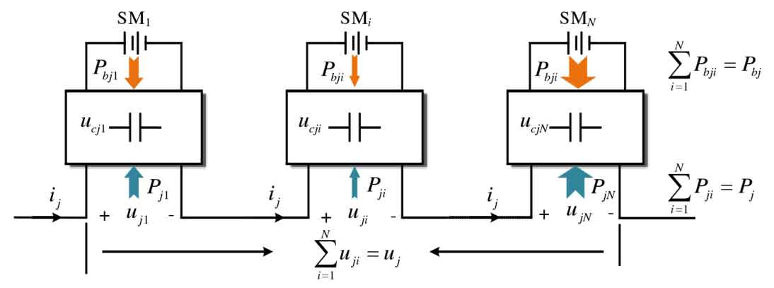
During steady state, the capacitor voltage remains stable, and the average power absorbed by the submodule from the MMC side and battery side is the same. There is a relationship between the port voltage uji and the bridge arm current ij:

Then, the power imbalance of the submodule meets the following requirements:

The sub modules within the same bridge arm are connected in series, and the current flowing through each sub module is equal to the bridge arm current ij. The formula can only be established by adjusting the sub module port voltage uji. For the half bridge submodule, its output voltage uji is limited to between 0 and the capacitor voltage ucji, and the average power Pji absorbed by the submodule from the MMC side is limited to a certain range. Therefore, the power imbalance of the submodule needs to be also limited to a certain range to maintain capacitor voltage balance.
The theoretical imbalance range that the submodules can achieve without considering factors such as modulation strategy is shown in Figure 2. When the bridge arm current ij>0, cut off the submodule to make its output voltage uji=0. When the bridge arm current ij ≤ 0, put the submodule into operation to make its output voltage uji=ucji, as shown in Figure 2 (a). If the integration of the submodule voltage uji and current ij is always negative, the power imbalance of the submodule reaches its maximum value λ Max (when the battery is discharged). Similarly, when the bridge arm current ij ≤ 0, the submodule is cut off, and when the bridge arm current ij>0, the submodule is put into operation, as shown in Figure 2 (b), then the power imbalance of the submodule reaches the minimum value λ Min (when the battery is discharged).
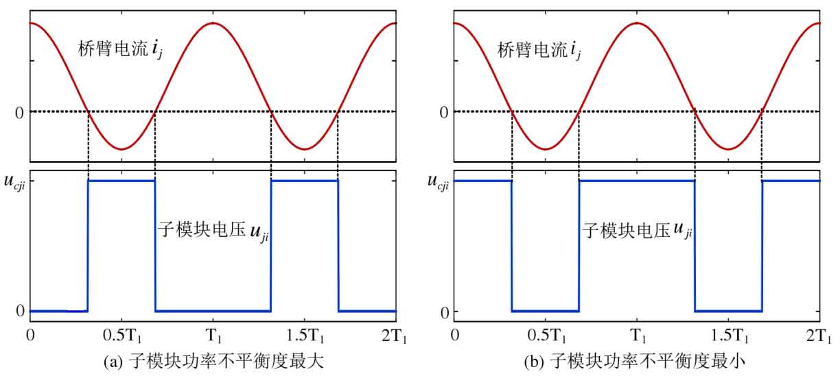
When the power imbalance of all sub modules within the same bridge arm is limited to λ Min~ λ When the maximum is between, the capacitor voltage of the submodule must be balanced, so this power imbalance range can reflect the balancing ability of the submodule. But in general, λ Min and λ Max is not asymmetric, and directly evaluating the balancing ability of submodules within this range is more complex, making it difficult to compare the balancing abilities of different control strategies and guiding the parameter design of SOC balancing controllers. For this reason, a more conservative approach to evaluating the balancing ability of submodules is adopted here, using only λ Min and λ The side closer to zero in max is used to evaluate the sub module balancing ability:

In the equation, ρ J is the evaluation of the balancing ability of the submodules in this chapter, as long as the power imbalance of the submodules inside the bridge arm is limited to – ρ J and ρ Between j, the capacitor voltage can inevitably maintain equilibrium. The greater the balancing ability of the submodule, the faster the allowed SOC balancing speed.
After evaluating the balancing ability of the submodules, according to the formula, the SOC balancing controller K3 needs to meet the following conditions:

However, it should be noted that in the actual system, the input and removal of each sub module inside the bridge arm are not arbitrary, and the constraint condition that the output voltage of the bridge arm is uj must be met, and it is also affected by the modulation strategy and capacitor voltage balance control strategy. Therefore, the range of sub module power imbalance allowed by the actual system λ Min~ λ Max is inevitably different from the ideal situation in Figure 2. Below, we will evaluate the balancing ability of the commonly used sub modules of capacitor voltage closed-loop balancing control and capacitor voltage sorting balancing control.
2. Evaluation of sub module balancing ability for capacitor voltage closed-loop balancing control
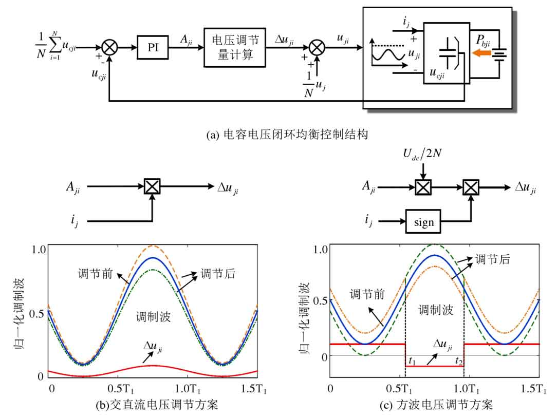
The capacitor voltage closed-loop equalization control is used for MMC systems using carrier phase shift modulation. The specific control structure is shown in Figure 3, which superimposes the adjustment amount on the voltage modulation waves of each submodule through the capacitor voltage closed-loop Δ Uji then adjusts the port voltage of the submodule to meet the power balance requirements in equations (4-3). The bridge arm current contains both the DC component and the fundamental frequency component. In theory, the port voltage regulation amount Δ As long as the direct current component or fundamental frequency component is included in uji, the adjustment of sub module power can be achieved. Figures 3 (b) and (c) show the two most commonly used adjustment methods currently. Figure 3 (b) takes the product of the output Aji of the capacitor voltage closed-loop controller and the bridge arm current ij as the sub module port voltage regulator ji Δ u. This method can simultaneously adjust the DC and AC components of the sub module port voltage, which is referred to as the AC/DC voltage regulation scheme. In Figure 3 (c), “sign” represents the symbol of the bridge arm current. When the bridge arm current is greater than 0, its value is 1, but when the bridge arm current is less than 0, its value is -1. The voltage regulation of the submodule port is in square wave form, which is referred to as the square wave voltage regulation scheme here. Below is an analysis of the balancing ability of these two commonly used submodule port voltage regulation methods. Prior to this, the following reasonable assumptions and related definitions are provided.
Ignoring the voltage drop on the filtering inductance and equivalent resistance, as well as the second or higher harmonic components in the bridge arm current, the output voltage and current of the bridge arm can be expressed as:
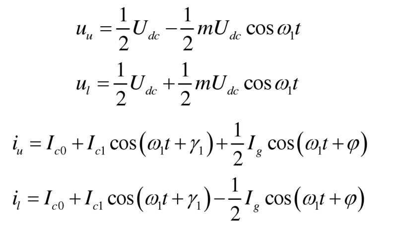
Among them, Ic1 and γ 1 is the amplitude and phase of the fundamental frequency component in the circulation, used to transfer power between the upper and lower bridge arms. There is a relationship between it and the battery power Pbu of the upper bridge arm and Pbl of the lower bridge arm, as follows:

When the power of the battery injected into the upper and lower bridge arms is unequal, there is a fundamental frequency component in the circulation, and the current in the upper and lower bridge arms is no longer symmetrical. To facilitate subsequent analysis, the bridge arm current is rewritten as follows:

In the equation, Iacu and φ U represents the amplitude and phase of the fundamental frequency component in the upper bridge arm current, Iacl and φ L represents the amplitude and phase of the fundamental frequency component in the lower bridge arm current.
According to the analysis of modular multilevel converter with integrated battery energy storage system power transmission, it can be seen that there is a relationship between the power Pacu and Pacl transmitted by the fundamental frequency current in the upper and lower bridge arms, battery power, and DC power Pdc as follows:

2.1 Sub module balancing ability of AC/DC voltage regulation scheme
Taking the above bridge arm as an example, according to the formula, when using the AC/DC voltage regulation scheme in Figure 3 (b), the sub module port voltage is:

Simultaneously define as follows:
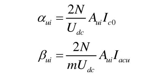
Among them, α UI is used to regulate the DC component in the output voltage of the submodule, which is referred to as the DC regulation factor here; β UI is used to regulate the AC component in the output voltage of the submodule, which is referred to as the AC regulation factor here. By substituting the formula, there is a relationship between the AC/DC regulation factor and the power imbalance of the submodule as follows:

In the equation, ξ U is the ratio of the DC component transmission power to the fundamental frequency component transmission power in the bridge arm:

ξ U represents the power transmission of the bridge arm, ξ U=1 indicates that the battery power in the bridge arm Pbu=0, ξ U<1 and ξ U>1 can represent different charging and discharging states of the battery; Taking Pdc>0 as an example, ξ When u<1, the battery is in a discharged state, ξ The smaller the u, the greater the discharge power of the battery, ξ When u=0, the battery power Pbu=Pacu, Pdc=0; ξ When u>1, the battery is in a charging state, ξ The larger the u, the greater the charging power of the battery. When the battery power Pbu=- Pdc/2, the fundamental frequency component of the bridge arm current transmits power Pacu=0, ξ U tends to infinity.
To avoid submodule overmodulation, according to the formula, the AC and DC regulation factors also need to meet the following constraint relationships:

The phase of the fundamental frequency component of the bridge arm current ξ When u=0, the formula can be simplified as:

According to the formula, the AC/DC regulation factor should be limited to the shaded area in Figure 4. In Figure 4 (a) φ U ≠ 0, the AC/DC regulation factor is limited to the area surrounded by two hyperbolas; In Figure 4 (b) φ U=0, the AC/DC regulation factor is limited to the area surrounded by four straight lines.
According to the formula, there is also a relationship between the AC and DC regulation factors:

In the equation, η U is the ratio of AC to DC regulation factors. The straight line in Figure 3 β Ui= η U α The intersection line segment EF between ui and the shaded area is the range of values for the AC/DC regulation factor under this operating condition. According to the formula, it is evident that when the AC/DC regulation factor is located at points E and F at the boundary, the power imbalance of the submodule will reach its maximum value λ Max and min λ Min.
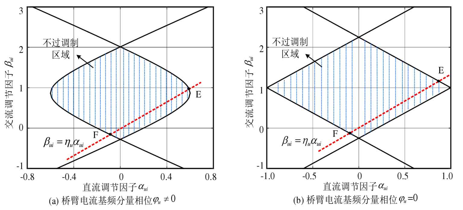
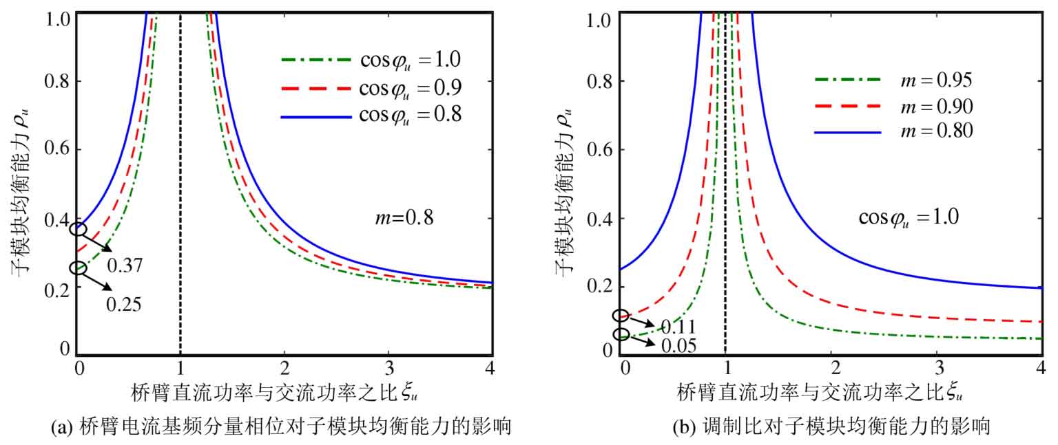
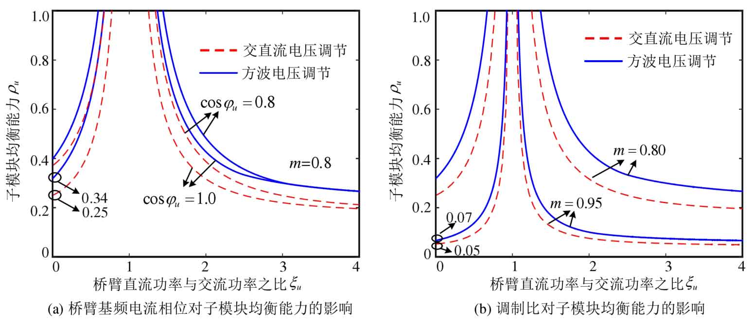
According to the formula, calculate the AC/DC regulation factors at points E and F( α E, β E) and( α F, β F), substituted into the formula to obtain λ Max and λ After min, the sub module balancing ability can be obtained based on the formula, as shown in Figure 5. When 0 ≤ ξ When u<1, with ξ The balance ability of sub modules gradually increases with the increase of u; ξ When u ≥ 1, with ξ As u increases, the balancing ability of the submodules gradually decreases ξ When u=1 is around, the balancing ability of the submodule is greater because the battery power is smaller at this time. In Figure 5 (a), with the increase of the fundamental frequency component phase angle u Å in the bridge arm current, the equalization ability of the submodule increases, with m=0.8, ξ Taking u=0 as an example, cos φ When u=1.0, the submodule balancing ability is 0.25, and when cos φ When u=0.8, the balancing ability of the submodule increases to 0.37. In Figure 5 (b), as the modulation ratio m increases, the equalization ability of the submodule rapidly decreases. This is because the amplitude of the allowed voltage regulation of the submodule port in the system also decreases as the modulation ratio increases. At modulation ratio m=0.95, cos φ U=1.0 ξ When u=0, the sub module’s balancing ability is only 0.05.
2.2 The sub module balancing ability of square wave voltage regulation scheme
Taking the above bridge arm as an example, when using the square wave voltage regulation scheme in Figure 3 (c), the output voltage of the submodule is:

By substituting the formula, there is a relationship between the power imbalance of the submodule and the amplitude of the square wave voltage as follows:

When | Ic0 | ≥ | Iacu |, there is no zero crossing point for the bridge arm current, and the formula can be simplified as follows:
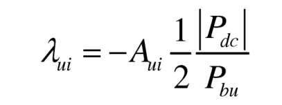
When | Ic0 |<| Iacu |, as shown in Figure 3 (c), there are two zero crossing points t1 and t2 for the bridge arm current:
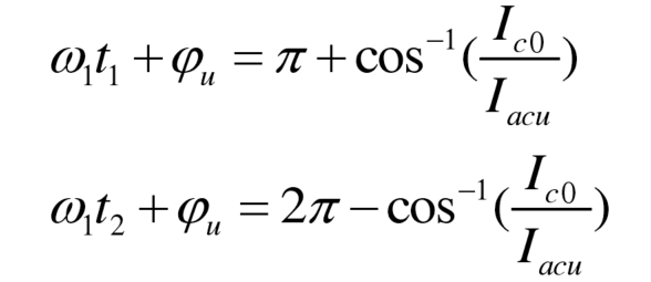
The formula can be simplified as:

To avoid the constraint conditions of submodule over modulation, the square wave voltage amplitude satisfies the relationship:

So, when using the square wave voltage regulation scheme, the balancing ability of the submodule is:

According to the formula ξ The definition of u transforms the variables in the formula into ξ u. The sub module equalization ability when using the square wave voltage regulation scheme is shown in Figure 6, and compared with the AC/DC voltage regulation scheme. When using a square wave voltage regulation scheme, the equalization ability of the submodule varies with ξ u. Modulation ratio m, bridge arm fundamental frequency current phase ξ The change trend of u is the same as that of the AC/DC voltage regulation scheme. Under the same operating conditions, the sub module balancing ability of the square wave voltage regulation scheme is always greater than that of the AC and DC voltage regulation scheme, with m=0.8 ξ U=0, cos φ Taking u=1.0 as an example, as shown in Figure 6 (a), the sub module equalization ability of the square wave voltage regulation scheme is 0.34, and the sub module equalization ability of the AC/DC voltage regulation scheme is 0.25. Under high modulation ratio, the difference between square wave voltage regulation scheme and AC/DC voltage regulation scheme rapidly decreases, as shown in Figure 6 (b), with modulation ratio m=0.95 and cos φ When u=1.0, the sub module balancing ability of the square wave voltage regulation scheme is 0.07, slightly higher than 0.05 of the AC/DC voltage regulation scheme.
3. Evaluation of sub module balancing ability for capacitor voltage sorting and balancing control
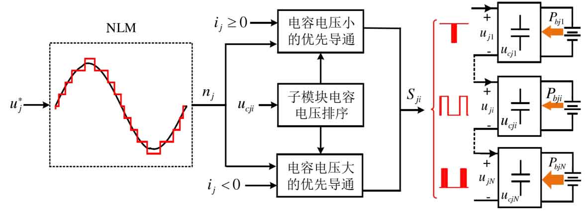
The capacitor voltage balancing control based on sorting algorithm is often combined with PD-PWM and NLM modulation, and the specific control structure is shown in Figure 9. Taking NLM as an example, the number of sub modules nj required to conduct the bridge arm is determined based on the amplitude of the modulation wave in each switching cycle, so that the output voltage approaches the modulation wave. Then, based on the sorting of capacitor voltage, select the submodules for conduction. The basic principle is: when the bridge arm current ij ≥ 0, prioritize the submodules with smaller capacitor voltage, and when the bridge arm current ij<0, prioritize the submodules with larger capacitor voltage.
3.1 Power imbalance range of submodules
Similar to Figure 2, taking battery discharge as an example. When the bridge arm current iu ≥ 0, the submodule is cut off, and when the bridge arm current iu<0, the submodule is put into operation. The power imbalance of the submodule will reach its maximum value λ Max. Similarly, when the bridge arm current iu<0, the submodule is cut off, and when the bridge arm current iu ≥ 0, the submodule is put into operation, and the power imbalance of the submodule will reach the minimum value λ Min. Combining the specific constraints of bridge arm current and bridge arm output voltage, the power imbalance degree is λ Max and λ The sub module port voltage at min is shown in Figures 8.
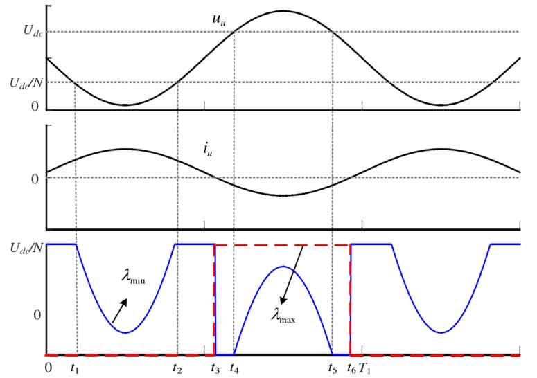
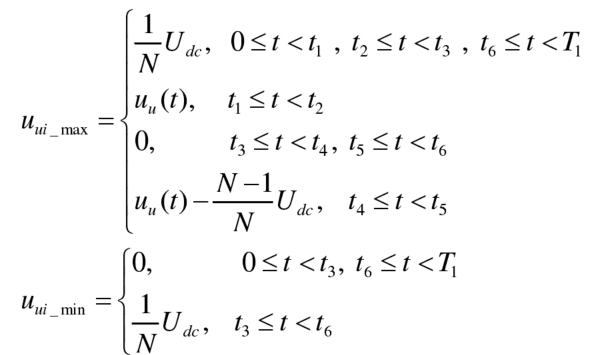
When the bridge arm current iu ≥ 0, if the bridge arm voltage uu<Udc/N, λ The output voltage of the sub module corresponding to min is uu. If uu ≥ Udc/N, λ The sub module corresponding to min will always be on, with an output voltage of Udc/N. When the bridge arm current iu<0, if the bridge arm voltage uu<(1-1/N) Udc, λ The sub module corresponding to min can always be in the cut off state, otherwise it will bear a portion of the output voltage uu – (1-1/N) Udc of the bridge arm. And λ The sub module corresponding to max can always be in the cut off state when the bridge arm current iu ≥ 0, and can always be in the conduction state when the bridge arm current iu<0. Finally, the power is λ Min and λ Equivalent output voltage ui of sub modules of max_ Mini and UI_ Maxu is:
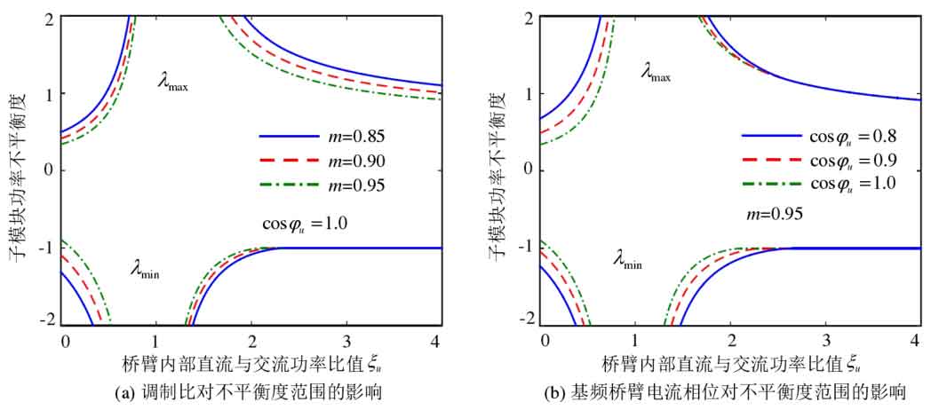
Substituting the formula into the system can obtain the allowable range of sub module power imbalance when using sorting algorithms λ Min~ λ Max, as shown in Figures 9. Obviously, even at high modulation ratios, sorting algorithms still allow for significant sub module power imbalance. However, when using capacitor voltage sorting and balancing control, the opening and closing of each submodule are not independent of each other, and not all submodules in the same bridge arm can reach the imbalance range shown in Figure 4-9. Therefore, when using capacitor voltage sorting and balancing, it is not possible to directly analyze the balancing ability of a single submodule. The proposed submodule balancing ability evaluation method is no longer applicable and needs to be improved appropriately.
3.2 Sum of sub module balancing capabilities
Since it is not possible to evaluate the balancing ability of a single submodule, the submodules within the bridge arm are directly considered as a whole, and the sum of the balancing abilities of the submodules is evaluated. At this point, submodules can be divided into two categories based on power imbalance: one is the power imbalance of submodules λ If ui ≥ 0, the number is n, denoted as G1, and its maximum output voltage is n/NUdc. Power imbalance of another type of submodule λ If ui<0, the number is N-n, denoted as G2, and its maximum output voltage is (1-n/N) Udc. Due to the transformation of the evaluation object into the sum of the balancing capabilities of sub modules, the differences between similar sub modules can be ignored in subsequent analysis, and it is considered that their power imbalance is the same.
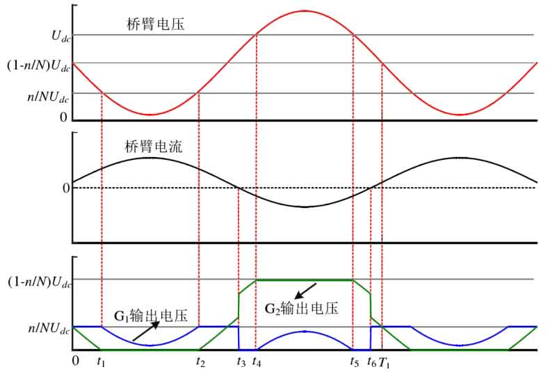
Taking battery discharge as an example, when the bridge arm current iu ≥ 0, prioritizing the conduction of sub modules in G1 can achieve the maximum sum of imbalances in that group of sub modules, denoted as λ∑ Max; When the bridge arm current iu ≥ 0, the submodules in G2 should be prioritized for conduction, which can minimize the sum of the imbalances of that group of submodules, denoted as λ∑ Min. According to this principle, ignoring the harmonic components in the output voltage of the submodule, the output voltage of the submodule within a fundamental frequency cycle is shown in Figure 4-10. Among them, t3 and t6 are the zero crossing points of the bridge arm current, t1 and t2 are the intersection points of the bridge arm output voltage and n/NUdc, and t4 and t5 are the intersection points of the bridge arm output voltage and (1-n/N) Udc.
During the 0-t1 stage, if the bridge arm current is greater than 0, the submodules in G1 are prioritized for conduction. However, due to the bridge arm output voltage being greater than the maximum output voltage n/NUdc of the submodules in G1, the additional bridge arm voltage is provided by the submodules in G2. The same situation applies to the t2-t3 stage and the t6-T1 stage. The voltage of the bridge arm in the t1-t2 stage can be completely provided by the submodules in G1. The bridge arm current in the t3-t4 stage is less than 0, and the output voltage of the bridge arm can be completely provided by the submodules in G2. The same situation exists in the t5-t6 stage; The bridge arm voltage in stage t4-t5 exceeds the maximum output voltage (1-n/N) Udc of the G2 neutron module, and the additional output voltage is provided by the G1 neutron module. The equivalent output voltages of the G1 and G2 submodules, uG1 and uG2, are:
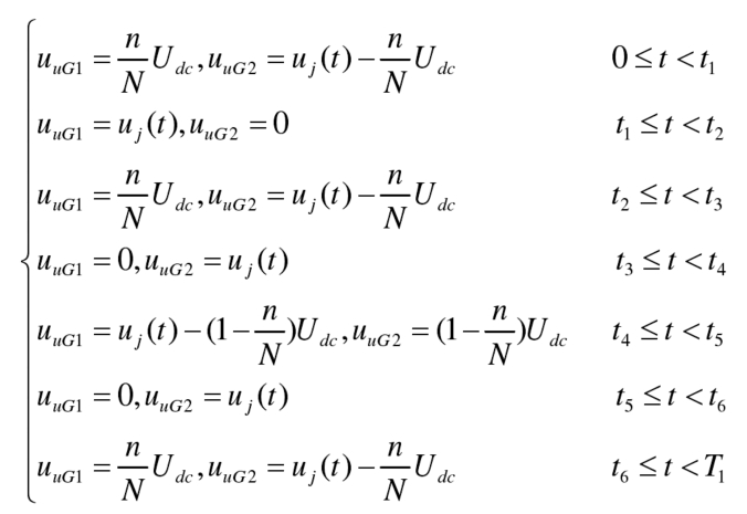
According to the formula, the maximum imbalance of the G1 neutron module λ∑ Minimum average imbalance between max and G2 neutron modules λ∑ Min can be calculated by the following method:
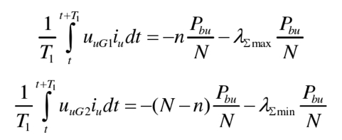
Add the formulas together, λ∑ Max and λ∑ There is a relationship between min:

According to the formula for defining the balancing ability of the sub modules, the total balancing ability of the bridge arm sub modules can be obtained when using capacitor voltage sorting balancing control ρ∑ U is:

Sum of sub module balancing capabilities ρ∑ U represents the sum of the imbalance degrees of the G1 submodule and the G2 submodule in the bridge arm- ρ∑ U- ρ∑ When u is between, the capacitor voltage of the sub modules inside the bridge arm must be balanced.
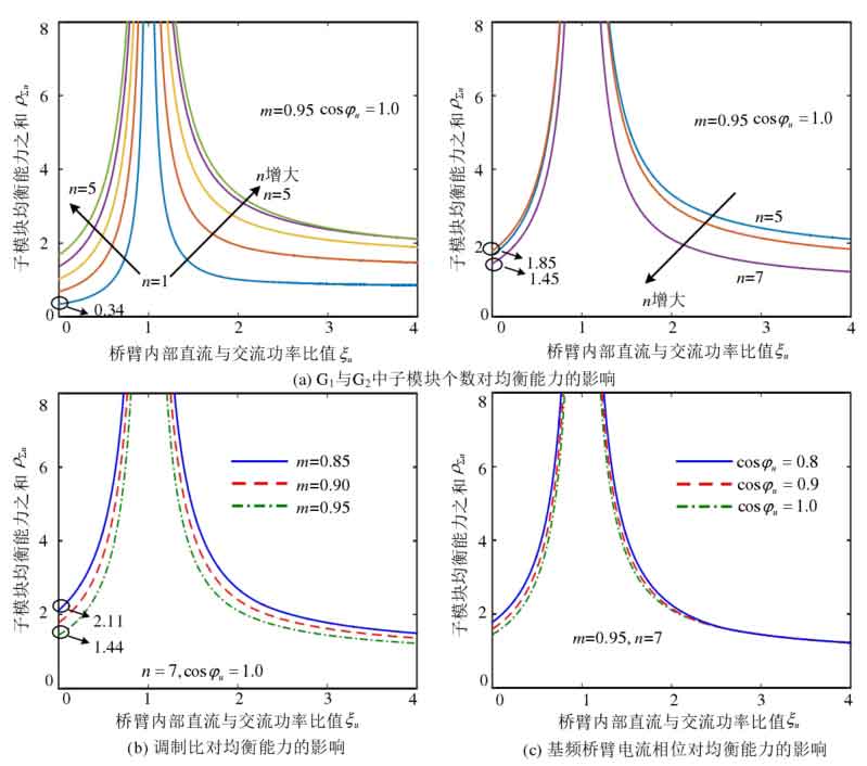
Substitute the formula into and obtain the total balancing capacity of the submodules based on the formula ρ∑ u. Taking the number of sub modules N=8 as an example, the results are shown in Figures 11. Sum of sub module balancing capabilities ρ∑ U with ξ The change trend of u is the same as that of capacitor voltage closed-loop equalization control, at 0 ≤ ξ When u<1, follow ξ The equilibrium ability gradually increases with the increase of u ξ u> 1 hour, with ξ The increase in u reduces the balance ability. In addition, the sum of sub module equalization capabilities is also influenced by the number of sub modules n, modulation ratio m, and fundamental frequency bridge arm current phase in G1 and G2 φ The impact of u. The balancing ability when the number of submodules in G1 and G2 changes is shown in Figure 11 (a). As the number of submodules in G1 increases, the sum of submodule balancing abilities first increases and then decreases. When n=1, the sum of submodule balancing abilities is the smallest, with m=0.95 ξ U=0, cos φ Taking u=1.0 as an example, the sum of submodule balancing capabilities ρ∑ U=0.34. As the modulation ratio m increases, the equalization ability gradually decreases, as shown in Figure 11 (b), with n=7 ξ U=0, cos φ Taking u=1.0 as an example, the sum of equalization capabilities when the modulation ratio m=0.85 ρ∑ U=2.11, but when m=0.95, the equilibrium ability decreases to ρ∑ U=1.44. Figure 11 (c) shows the equalization ability when the phase u Å of the fundamental frequency bridge arm current changes, as φ The decrease of u gradually increases the balance ability, but its impact on the balance ability is relatively small.
After obtaining the sum of sub module balancing capabilities ρ∑ After u, due to the inability to obtain the balancing ability of each internal sub module, the SOC balancing controller parameters are designed based on the average balancing ability of the sub modules. For sub modules in G1:

For sub modules in G2:

K3, which simultaneously satisfies the formula, is the selectable range of SOC equilibrium controller parameters.
4. Scheme for improving the balancing ability of sub modules in capacitor voltage closed-loop control
The closed-loop balancing control of capacitor voltage is constrained by submodule overmodulation, and the balancing ability of submodules rapidly decreases at high modulation ratios, making it difficult to meet the fast balancing requirements of SOC. To address this issue, based on the traditional capacitor voltage closed-loop equalization control in Figure 3, an improved adjustment scheme for the sub module port voltage is proposed to enhance the sub module equalization ability.
4.1 Optimized AC/DC voltage regulation scheme
In the AC/DC voltage regulation scheme of Figure 3 (b), the AC/DC regulation factor is limited to the shaded area and straight line in Figure 4 β Ui= η U α Intersection segment EF of ui. The slope of a straight line η There is a relationship between u and the power transmission of the bridge arm in the formula, which means that after the power transmission of the bridge arm is determined, the AC/DC adjustment factor can only be taken in the line segment EF. If the slope of a straight line η If u is not limited to a formula, the AC/DC adjustment factor can be freely taken within the shaded area, which is beneficial for improving the balancing ability of the submodules. Therefore, the key to the problem lies in how to determine the appropriate η U.
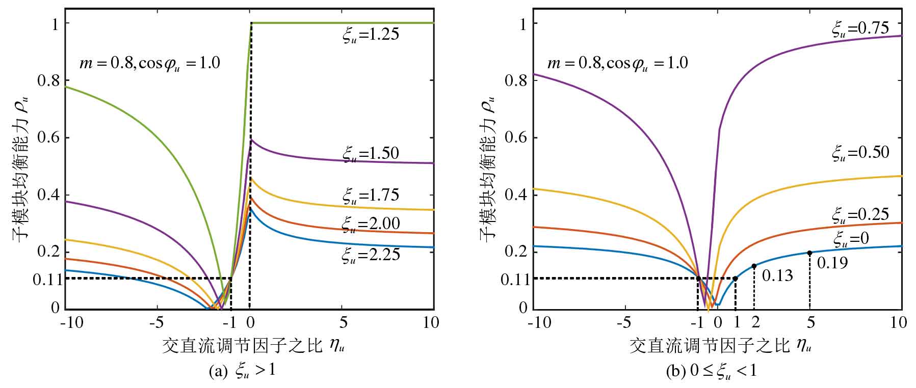
Calculate the ratio of different AC/DC regulation factors based on the calculation method of sub module balance ability η The sub module balancing ability under u is shown in Figure 13. In Figure 13 (a) ζ U1, with η The balance ability of the submodule gradually decreases to 0 and then gradually increases as u increases η When u=0, it reaches its maximum value and gradually decreases, eventually tending to remain unchanged. This indicates that when ζ u> At 1 hour, only adjusting the DC component of the sub module port voltage can maximize the sub module equalization ability. In Figure 13 (b), 0 ≤ ζ U<1, with η The balance ability of the submodule with an increase in u decreases first and then increases. From the trend of change, it can be seen that η When u approaches infinity, the balancing ability of the submodules reaches its maximum value. That is, at this point, the DC regulation factor α UI=0, only adjusting the AC component of the sub module port voltage can maximize the sub module equalization ability. All curves pass through fixed points (-1, 0.11), at which point the AC/DC regulation factor α Ui=- β The equalization ability of the sub module is independent of the power transmission of the bridge arm.
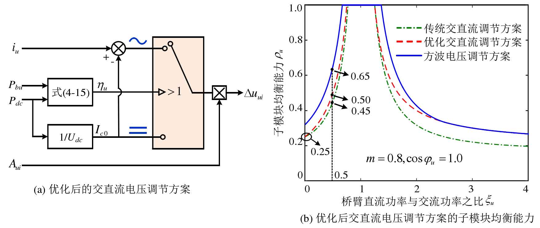
Based on the above analysis results, the optimized AC/DC voltage regulation scheme is shown in Figure 14 (a). Calculate the DC component Ic0 in the bridge arm current based on the DC side power, subtract the DC component from the bridge arm current to obtain the AC component, and then η U determines whether to adjust the DC or AC flow rate. At this point, the balancing ability of the submodule is shown in Figure 14 (b) ζ u> At 1 hour, the balancing ability of the submodule has significantly improved compared to traditional AC/DC regulation schemes, while at 0 ≤ ζ The effect of improving balance ability within the range of u<1 is relatively limited. The sub module balancing ability of the optimized AC/DC voltage regulation scheme before and after optimization is smaller than that of the square wave voltage regulation scheme ζ Taking u=0.5 as an example, the optimized AC/DC voltage regulation scheme increases the balancing ability of the submodule from 0.45 to 0.50, while the square wave voltage regulation scheme is 0.65.
4.2 Voltage regulation scheme suitable for high modulation ratio
Compared to the AC/DC voltage regulation scheme, the square wave voltage regulation scheme has greater sub module equalization ability, but it still faces the problem of low equalization ability under high modulation ratio. In Figure 6, at m=0.95 ζ U=0, cos φ When u=1.0, the sub module equalization ability of the square wave voltage is only 0.07, which obviously cannot meet the demand for fast SOC equalization.
In the current sub module output voltage regulation scheme, overmodulation only occurs at the maximum modulation wave, and is far from being overmodulated in other regions. The output voltage range of the sub module has not been fully utilized. Taking the square wave voltage regulation scheme as an example, as shown in Figure 15 (a), the shaded area represents the unused area of the output voltage of the submodule. Therefore, the output voltage regulation of the submodule Δ The amplitude of uji should not be fixed and unchanging, but should change with the modulation wave of the submodule. It can be appropriately increased when the modulation wave of the submodule is small Δ The amplitude of uji is used to fully utilize the output voltage range of the submodule, and is appropriately reduced when the modulation wave of the submodule is large Δ The amplitude of uji to avoid submodule overmodulation.
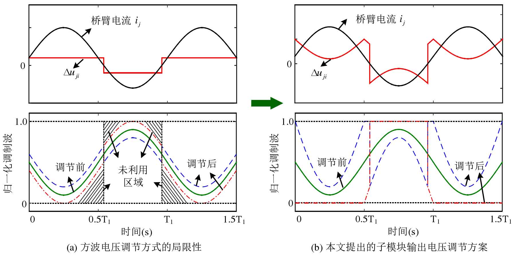
Based on the above analysis, taking the upper bridge arm as an example, the proposed method for adjusting the output voltage of the submodule with high modulation ratio is shown in Figure 15 (b). The expression for the voltage regulation amount of the submodule port is:

When the bridge arm voltage uu is closer to Udc, Δ Uui is determined based on the difference between uu and Udc, otherwise Δ Uui is determined based on uu. When Aui=1, Δ The amplitude of uui reaches its maximum, as shown by the dotted line in Figure 15 (b). At this point, the unused areas in Figure 15 (a) are fully utilized, and the equalization ability of the submodules will be greatly improved. When Aui=-1, Δ The amplitude of uui is the smallest, as shown by the dash in Figure 15 (b), and the submodule has not been overmodulated.
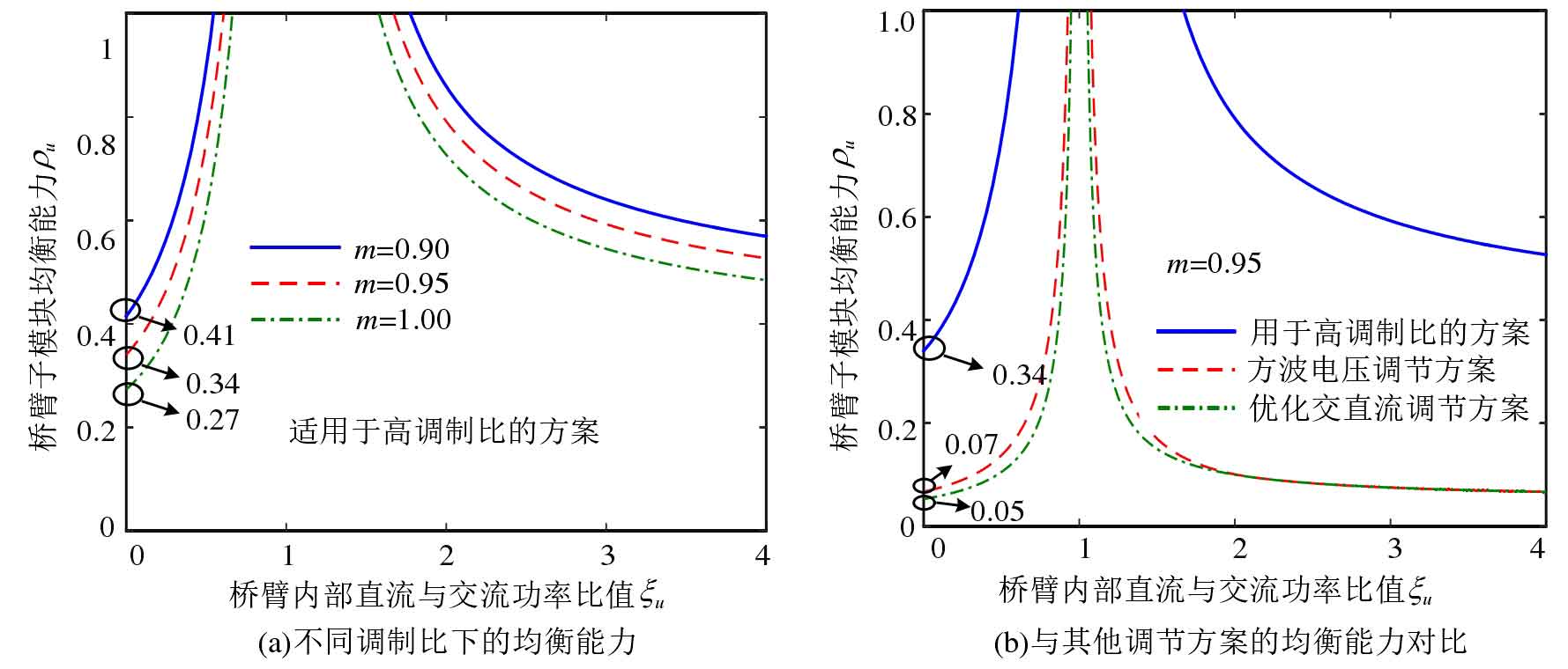
According to the formula, the sub module equalization ability of the voltage regulation scheme suitable for high modulation ratio can be obtained, as shown in Figure 16. Under high modulation ratio, the proposed sub module port voltage regulation scheme still has high sub module equalization ability, as shown in Figure 16 (a), ξ When u=0 and m=0.95, the equalization ability of the submodule is 0.34. Even if the modulation ratio increases to m=1.0, the equalization ability of the submodule is still as high as 0.27. The comparison of sub module equalization capabilities among different voltage regulation schemes is shown in Figure 16 (b). The square wave voltage regulation scheme has a sub module equalization capability of only 0.07 at m=0.95, while the AC/DC voltage regulation scheme has a lower equalization capability of only about 0.05. It can be seen that the proposed sub module output voltage regulation method has significant advantages in high modulation ratios.
5. Simulation and experimental verification
5.1 Simulation verification
In order to verify the analysis and control strategy, corresponding simulation platforms were built to verify the balance control strategies of two sub modules: capacitor voltage closed-loop balance control and capacitor voltage sorting balance control. The main circuit parameters on the MMC side are consistent with those in the table. The energy storage unit is a lead-acid battery, with a rated voltage of 1kV. It is connected to the MMC submodule through a half bridge buck/boost bidirectional DC/DC converter. In order to reduce the convergence time of battery SOC, the capacity of the battery cell is only set to 0.3Ah. In this section of simulation verification, the DC power Pdc=0, the AC side is the unit power factor, and the fundamental frequency circulating current phase is in phase with the output voltage of that phase, which is the ratio of bridge arm DC power to AC power ξ J=0, phase cos of the fundamental frequency component of the bridge arm current φ J=1.0.
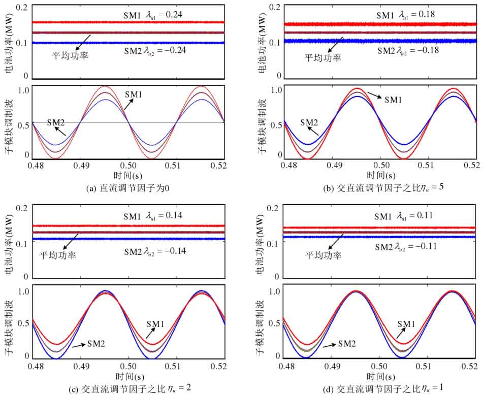
The closed-loop equalization control of capacitor voltage in Figure 17 adopts an AC/DC voltage regulation scheme. When the DC regulation factor is equal to 0, the equalization ability of the submodule can be maximized, theoretically reaching 0.25. In the simulation, the output of the capacitor voltage closed-loop controller is not limited, and the power imbalance of the submodules is gradually increased until overmodulation to obtain the submodule equalization ability. During this process, the capacitor voltage is always balanced, so the simulation results are no longer given. In Figure 17 (a), only the AC amount in the port voltage is adjusted. When the battery power imbalance is 0.24, the submodule is close to being modulated, which means that the submodule’s equalization ability is 0.24, which is consistent with the evaluation results. Then, in Figure 17 (b), (c), and (d), gradually increase the proportion of the DC regulation factor and select η U=5 η U=2 η Three adjustment schemes with u=1 were validated, and according to Figure 12, it can be seen that the sub module balancing abilities of these three schemes are 0.19, 0.13, and 0.11, respectively. The simulation results are also close to the evaluation results, with the battery power imbalance of 0.18, 0.14, and 0.11 when the submodule is overmodulated.
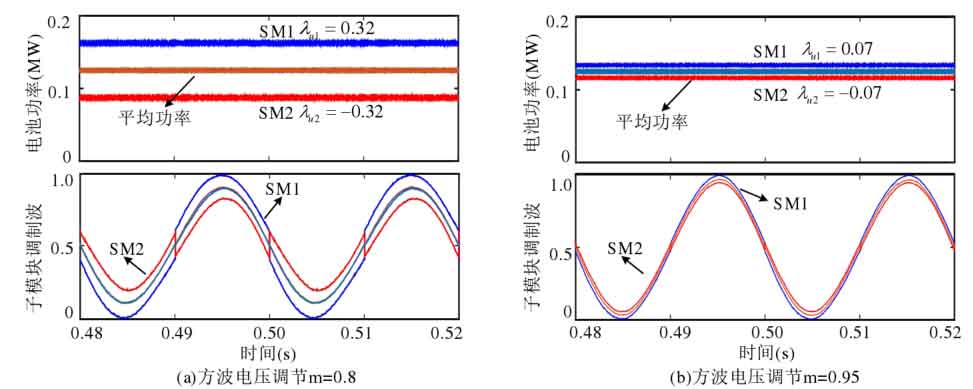
The closed-loop equalization control of capacitor voltage in Figure 18 adopts a square wave voltage regulation scheme, and two working conditions with modulation ratios m of 0.8 and 0.95 are selected for verification. According to the analysis in Figure 6, it can be seen that the equalization capabilities of sub modules in these two working conditions are 0.34 and 0.07, respectively. In Figure 18 (a), the modulation ratio is 0.8, and when the power imbalance of the sub module reaches 0.32, the sub module is close to overmodulation. In Figure 18 (b), the modulation ratio increases to 0.95, and when the power imbalance of the sub module is only 0.07, the sub module is close to overmodulation, which is consistent with the theoretical analysis results.
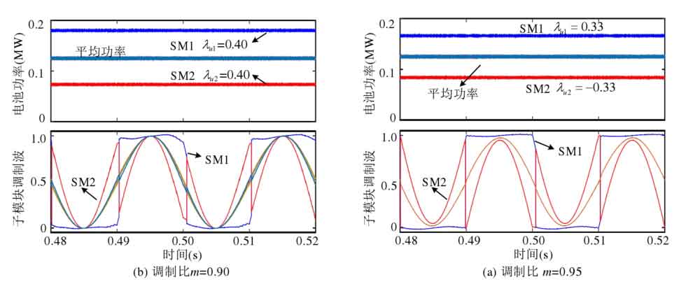
To verify the effectiveness of the sub module port voltage regulation scheme proposed in this article for high modulation ratio, two operating conditions with modulation ratio m of 0.90 and 0.95 were selected for simulation verification in Figure 19. According to Figure 16, it can be seen that the sub module’s equalization ability is 0.41 and 0.34, respectively. In Figure 19 (a), when the modulation ratio m=0.90 and the power imbalance of the sub module is 0.40, the sub module is still not over modulated. In Figure 19 (b), when the modulation ratio increases to m=0.95 and the power imbalance of the sub module is 0.33, the sub module is still not over modulated. Compared with the square wave voltage regulation scheme, the equalization capability of the sub module is significantly improved.
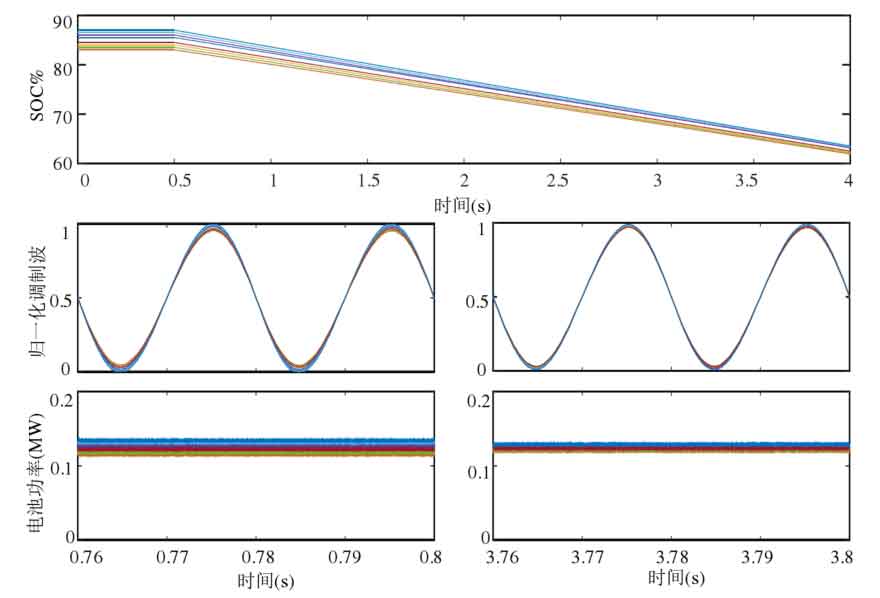
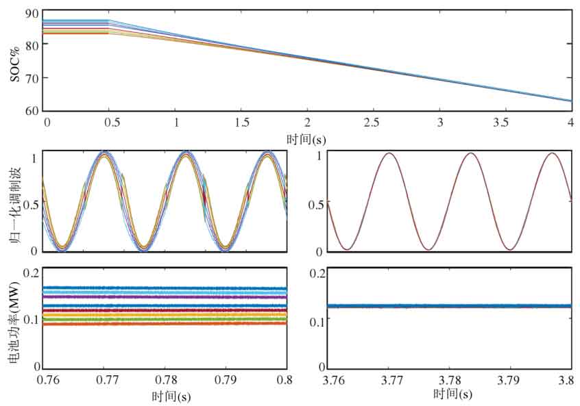
Figure 20 and Figure 21 show the SOC equalization process of a bridge arm, where the modulation ratio m=0.95. Figure 20 adopts an AC/DC voltage regulation scheme, and the parameter K3 of the SOC equalization controller is designed according to equations (4-6), with the maximum value taken. When SOC begins to equalize, the submodule approaches overmodulation, and the equalizing speed has reached the maximum value under this working condition, but the equalizing speed is very slow. When T=4.0s, SOC has not yet achieved equalization. The sub module port voltage regulation scheme proposed in this chapter for high modulation ratio is adopted in Figure 21, and the SOC achieves good equalization effect at T=3.0s.
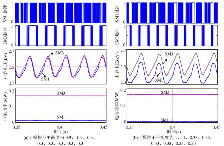
The simulation in Figure 22 adopts capacitor voltage sorting balance control, with a modulation strategy of PD-PWM and a modulation ratio of 0.95. In order to facilitate the verification of the balancing ability of the submodules, the power imbalance degree of each submodule is directly given. The power imbalance degrees of the 8 sub modules in Figure 22 (a) are -0.9, -0.9, 0.3, 0.3, 0.3, 0.3, 0.3, and 0.3, respectively. According to Figure 12, the total balancing capacity of the submodules at this time is 1.85, and the total power imbalance of the submodules is 1.8. If the balancing capacity of the submodules is not exceeded, the capacitor voltage will continue to maintain balance, and the simulation results show that the capacitor voltage remains stable. In Figure 22 (b), continue to increase the power imbalance of the submodules by -1.0, -1.0, 0.33, 0.33, 0.33, 0.33, 0.33, and 0.33. The sum of the power imbalance of the submodules is 2.0, which exceeds the balancing capacity of the submodules, so the capacitor voltage cannot be maintained stable. It can be seen that the analysis of sub module balancing ability for capacitor voltage sorting and balancing has high accuracy.
5.2 Experimental verification
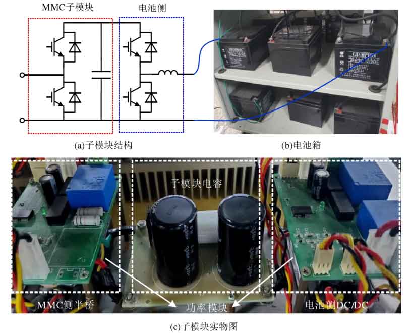
On the basis of the original MMC experimental platform, the modular multilevel converter with integrated battery energy storage system experimental platform was formed by integrating battery cells into submodules. The submodule structure is shown in Figure 23. The battery unit adopts lead-acid batteries, with a nominal voltage of 12V and a capacity of 20AH for a single battery. The battery pack of each submodule is composed of three battery units connected in series, and then connected to the submodule through a half bridge buck boost bidirectional DC/DC converter.
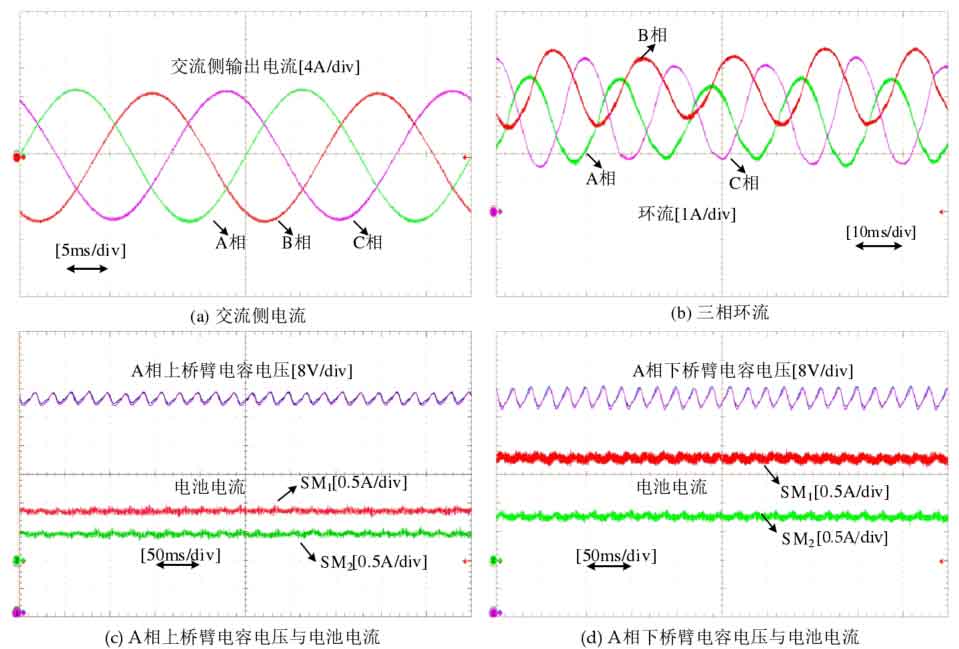
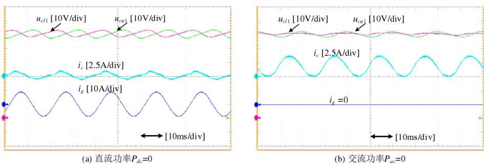
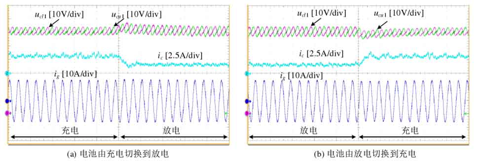
The steady-state operation waveform of modular multilevel converter with integrated battery energy storage system is shown in Figure 24. The three-phase AC output current is symmetrical and highly sinusoidal, with a peak phase current of approximately 10A. Due to the existence of SOC equalization control, the battery power injected into each phase, bridge arm, and submodule is uneven, resulting in the presence of fundamental frequency components in the circulation, and the DC components in each phase of the circulation are not equal. The battery power of each sub module inside the bridge arm is not equal, but the capacitor voltage can still maintain balance. Figure 25 shows two special operating conditions of modular multilevel converter with integrated battery energy storage system. In Figure 25 (a), the DC power Pdc=0, and the power is only transmitted on the AC side and battery side. The balancing ability of the submodules under this condition is relatively low, and subsequent verification in this chapter will be carried out under this condition. The AC port in Figure 25 (b) is not in operation, and power is only transmitted on the DC side and battery side. Figure 26 shows the battery charging and discharging switching experiment, with each controller still using the parameters designed in Chapter 3. During the process of battery charging and discharging state switching, the capacitor voltage between the bridge arms can still maintain equilibrium, and the capacitor voltage can quickly recover to the command value, exhibiting good dynamic characteristics.
In the experimental verification of the balancing ability of the submodule, the DC power Pdc is still set to 0, and the ratio of the bridge arm DC power to AC power is selected ξ Verify the working point of j=0. At the same time, the AC side is set as the unit power factor, and the issue of SOC balance control between phases and bridge arms is not considered temporarily, that is, the fundamental frequency component phase cos of each bridge arm φ J=1.0. In the closed-loop balancing control of capacitor voltage, the controller output is limited to avoid submodule overmodulation. When the power imbalance of the submodule exceeds the balancing capacity, the capacitor voltage will not be able to maintain balance.
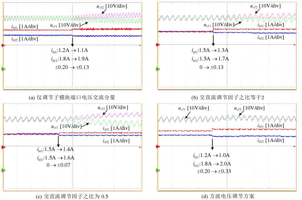
The verification of the sub module equalization ability of the AC/DC voltage regulation scheme and the square wave voltage regulation scheme is shown in Figure 27, with a modulation ratio of m=0.8. Figure 27 (a) only adjusts the AC component of the sub module port voltage. After increasing the battery power imbalance from 0.20 to 0.27, it exceeds the sub module equalization capacity by 0.25 (as shown in Figure 4-11), so the capacitor voltage cannot maintain balance. In Figures 27 (b) and (c), the DC component in the voltage regulation of the submodule port is gradually increased. When the power imbalance of the submodule is 0.13 and 0.07, respectively, the capacitor voltage is imbalanced, and the balancing ability of the submodule gradually decreases, which is basically consistent with the analysis results in Figure 13. Figure 27 (d) adopts a square wave voltage regulation scheme. After increasing the power imbalance of the battery from 0.20 to 0.33, it does not exceed its submodule equalization capacity of 0.34 (as shown in Figure 9), so the capacitor voltage remains balanced.
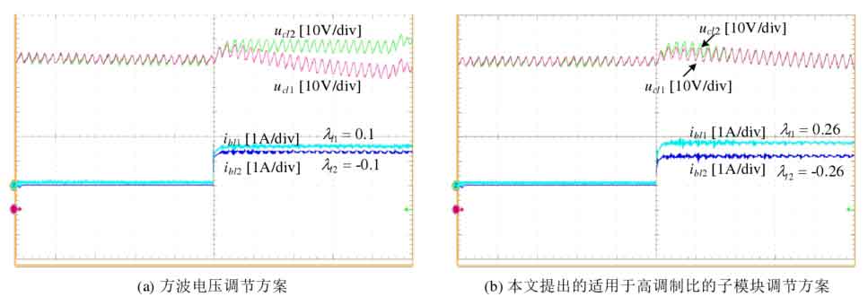
The sub module equalization ability of capacitor voltage closed-loop equalization control will rapidly decrease under high modulation ratio. Taking the square wave voltage regulation scheme as an example, its modulation ratio m=0.95 ξ When j=0, the balancing ability of the submodule is only 0.07, and the test results are shown in Figure 28 (a). When the power imbalance of the submodule is ± 0.1, the capacitor voltage can no longer be balanced. Figure 28 (b) adopts the sub module port voltage regulation scheme proposed in this article, which is suitable for high modulation ratio. When the sub module power imbalance is ± 0.26, the capacitor voltage can still maintain balance, indicating that it has good sub module balancing ability under high modulation ratio.
6. Summary
After integrating the battery energy storage system, the SOC equalization speed and the sub module capacitor voltage equalization interact and constrain each other. This chapter first defines the concept of sub module power imbalance, evaluates the sub module balancing ability using the allowable range of imbalance in the system, and serves as the design basis for SOC balancing controller parameters. Analyzed the sub module equalization ability of different port voltage regulation methods in capacitor voltage closed-loop equalization control, and the results showed that the square wave voltage regulation scheme had a greater equalization ability than the sub module of the AC/DC voltage regulation scheme. However, the closed-loop equalization control of capacitor voltage is constrained by modulation, and the equalization ability of submodules rapidly decreases at high modulation ratios. Therefore, this chapter proposes a submodule port voltage regulation scheme to improve the equalization ability of submodules at high modulation ratios. Unlike capacitor voltage closed-loop equalization control, when using capacitor voltage sorting equalization, each submodule is not independent of each other and the equalization ability of the submodules cannot be analyzed separately. To this end, the bridge arm submodules are considered as a whole, and the sum of their equalization capabilities is evaluated, and the SOC equalization controller parameters are designed using their average values. Finally, the accuracy of the evaluation method for sub module balancing capability and the effectiveness of the proposed improved control strategy were verified through detailed simulation and experimental results.
