
Achieving carbon peaking and carbon neutrality is a widespread and profound systemic transformation, and building a clean and low-carbon energy system is crucial. The integrated energy system (IES) can reduce energy consumption and carbon emissions, and promote the utilization of new energy through multi energy synergy. Battery energy storage has advantages such as high energy density, fast response speed, and modularity, which can suppress fluctuations in new energy output and is widely used in IES. However, battery energy storage poses thermal safety risks and life decay issues, which pose challenges in terms of thermal safety and economy.
In battery energy storage, individual batteries are combined in series and parallel to ensure that the capacity, output power, and other parameters meet the operational requirements of the system. The power output capacity of battery energy storage is affected by the temperature of the battery. When the temperature is too high or too low, the energy storage output capacity of the battery weakens and the life decay intensifies. It was found that low-temperature charging and discharging of the battery resulted in lithium evolution, leading to a decrease in recyclable lithium ions and a sharp decrease in battery life. At the same time, lithium dendrites grew, piercing the battery separator and causing internal short circuits, causing safety issues. It was found that excessive operating temperature of lithium-ion batteries can lead to side reactions such as thickening and decomposition of the solid electrolyte interface (SEI) film, as well as gas production, leading to excessive internal pressure and, in severe cases, fire and explosion. Cyclic aging experiments were conducted on lithium iron phosphate batteries at -10~60 ℃, and it was found that operating the battery at high or low temperatures would exacerbate capacity degradation. In the management of battery energy storage operation, it is necessary to consider the impact of temperature on the thermal safety and life decay of batteries, in order to ensure the continuous, safe and reliable operation of battery energy storage.
The temperature of battery energy storage is influenced by the coupling of self charging and discharging heat generation and environmental temperature. Currently, most battery energy storage management systems monitor battery temperature by collecting the surface temperature of the battery, which has low prediction accuracy. The battery parameters can be estimated through a combination of experiments and simulations to establish a battery temperature estimation model, which monitors the internal electrolyte reaction temperature of the battery and avoids excessively high or low reaction temperature inside the battery. A modeling method for lithium-ion batteries was proposed, which combines recursive least squares and extended Kalman filtering algorithm to estimate the average temperature of lithium-ion batteries. Establish a battery thermoelectric coupling model, design a bidirectional pulse operating condition experiment, use adaptive particle swarm optimization algorithm to identify model parameters, and estimate the surface temperature of the battery with an error of within 0.1 ℃. Reference [15] applied the state space method to transform partial differential equations into ordinary differential equations, and established a fast estimation method for voltage and temperature in the electrochemical thermal model of battery aggregation, which can reduce the calculation time of the model by more than 50%. The above article studied the estimation of battery temperature and heat generation rate. The current problem that needs to be solved is the complex expression for calculating battery temperature and heat generation rate, which cannot be embedded in the IES optimization model.
There has been extensive research on the optimization scheduling of IES with battery energy storage by scholars. Battery energy storage does not directly incur costs during operation, but there is a lifespan loss every time it is charged or discharged. Neglecting the lifespan loss of the battery in the IES planning process will underestimate the cost of energy storage, resulting in system economy not meeting expectations. Propose a method for estimating the lifespan of large-scale energy storage batteries based on deep neural networks and an economic dispatch method for power systems that accurately considers the lifespan of large-scale energy storage batteries. It was found that changes in energy storage lifespan can have a significant impact on economic dispatch results. A mixed integer linear programming model for battery life decay was proposed, which comprehensively considers the depth of discharge (DOD) and state of charge (SOC). Based on the consideration of battery life decay, a daily economic dispatch model was established and its effectiveness was verified. A service life model for a large capacity battery energy storage system in the power system has been established, reflecting the effects of charging and discharging rate, temperature, and charging and discharging frequency on battery aging. Considering the impact of battery life and simplifying the cost of battery life loss, a study on the optimization scheduling of microgrids based on dynamic programming method is conducted. Reference proposes a method for calculating the aging cost of batteries and an optimized operation scheme for microgrids with battery energy storage systems, taking into account the operational characteristics of battery energy storage. The current IES optimization scheduling research has included the cost of battery life loss under different temperatures in the total cost, ignoring the limited output capacity of batteries under extreme high and low temperatures, which leads to the inability of battery energy storage to meet the scheduling requirements and output, resulting in accelerated life decay and incomplete consumption of new energy output under high and low temperature conditions.
To address the issues of rapid decay of battery energy storage life and poor performance under extreme high and low temperatures, a convex battery electrothermal coupling model is constructed through experiments and simulations to reveal the cumulative thermal effect of the battery and estimate the battery temperature; Analyze the characteristics of battery energy storage temperature power output capacity, temperature life decay, etc., and construct a battery energy storage operation model with temperature control; Build an IES low-carbon economic operation model with the goal of minimizing daily operating costs, construct a mixed integer optimization model, and develop an IES low-carbon economic scheduling plan. By comparing the proposed scheme with the method that does not include battery energy storage temperature control through different seasonal operating scenarios, the results show that the proposed scheme can improve the battery energy storage service life, thermal safety, and utilization rate, and promote the low-carbon economic operation of IES.
There has been extensive research on the optimization scheduling of IES with battery energy storage by scholars. Battery energy storage does not directly incur costs during operation, but there is a lifespan loss every time it is charged or discharged. Neglecting the lifespan loss of the battery in the IES planning process will underestimate the cost of energy storage, resulting in system economy not meeting expectations. Propose a method for estimating the lifespan of large-scale energy storage batteries based on deep neural networks and an economic dispatch method for power systems that accurately considers the lifespan of large-scale energy storage batteries. It was found that changes in energy storage lifespan can have a significant impact on economic dispatch results. A mixed integer linear programming model for battery life decay was proposed, which comprehensively considers the depth of discharge (DOD) and state of charge (SOC). Based on the consideration of battery life decay, a daily economic dispatch model was established and its effectiveness was verified. A service life model for a large capacity battery energy storage system in the power system has been established, reflecting the effects of charging and discharging rate, temperature, and charging and discharging frequency on battery aging. Considering the impact of battery life and simplifying the cost of battery life loss, a study on the optimization scheduling of microgrids based on dynamic programming method is conducted. A method for calculating the aging cost of batteries and an optimized operation plan for microgrids with battery energy storage systems are proposed, taking into account the operational characteristics of battery energy storage. The current IES optimization scheduling research has included the cost of battery life loss under different temperatures in the total cost, ignoring the limited output capacity of batteries under extreme high and low temperatures, which leads to the inability of battery energy storage to meet the scheduling requirements and output, resulting in accelerated life decay and incomplete consumption of new energy output under high and low temperature conditions.
To address the issues of rapid decay of battery energy storage life and poor performance under extreme high and low temperatures, a convex battery electrothermal coupling model is constructed through experiments and simulations to reveal the cumulative thermal effect of the battery and estimate the battery temperature; Analyze the characteristics of battery energy storage temperature power output capacity, temperature life decay, etc., and construct a battery energy storage operation model with temperature control; Build an IES low-carbon economic operation model with the goal of minimizing daily operating costs, construct a mixed integer optimization model, and develop an IES low-carbon economic scheduling plan. By comparing the proposed scheme with the method that does not include battery energy storage temperature control through different seasonal operating scenarios, the results show that the proposed scheme can improve the battery energy storage service life, thermal safety, and utilization rate, and promote the low-carbon economic operation of IES.
1. Convex battery electrothermal coupling model
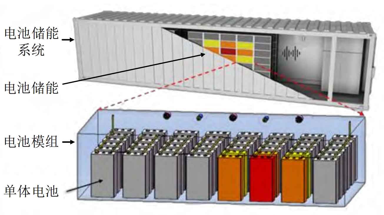
The structure of the battery energy storage system is shown in Figure 1, where a single battery is connected in series and parallel to form a battery module; The battery modules are tightly arranged to form battery energy storage; The battery energy storage system is composed of a battery energy storage bin, which is located together with a converter, battery management system, etc. This section constructs a convex battery electrothermal coupling model through individual battery characteristic experiments combined with finite element simulation, in order to estimate the battery temperature (internal average temperature) under the influence of battery charging and discharging coupling environmental temperature, and embed an optimized scheduling model.
Firstly, conduct battery characteristic experiments to identify battery parameters and construct an electrothermal coupling model based on the experiments; According to this model, the thermal power, electrical power, and battery temperature of the battery can be calculated at any time, but the expression of this model is complex and difficult to embed into the IES optimization model.
Based on the parameters obtained from experimental identification and the expressions of electrical and thermal power in the electrothermal coupling model, a battery simulation model is built in finite element simulation software to verify the accuracy of the simulation model in predicting battery temperature rise; Based on the simulation data and experimental identification parameters, a convex thermoelectric coupling model that can be embedded into the IES optimization model is constructed.
1.1 Battery Characteristics Experiment
Constant current discharge, pulse discharge, and battery temperature rise experiments were conducted at different environmental temperatures (-20~45 ℃). In the constant current discharge experiment, the battery is charged at a constant temperature of 25 ℃ and discharged to the cut-off voltage at different constant temperatures to obtain a temperature battery capacity curve. In the pulse discharge experiment, the battery is charged at a constant temperature of 25 ℃ and pulsed at different constant temperatures to identify the internal resistance of the battery at different temperatures and SOC, as well as the SOC open circuit voltage (OCV) curve of the battery at different temperatures. In the battery temperature rise experiment, the battery is charged at a constant temperature of 25 ℃ and discharged at different rates at a constant environmental temperature of 25 ℃. The battery temperature is recorded to obtain parameters such as the specific heat capacity and convective heat transfer coefficient of the battery.
1.2 Battery electrothermal coupling model
The battery electrothermal coupling model consists of a heat generation model and a heat transfer model. The heat generation model describes the heat generation during battery charging and discharging, while the heat transfer model describes the heat exchange between the battery and the external environment.
1) Battery heat generation model
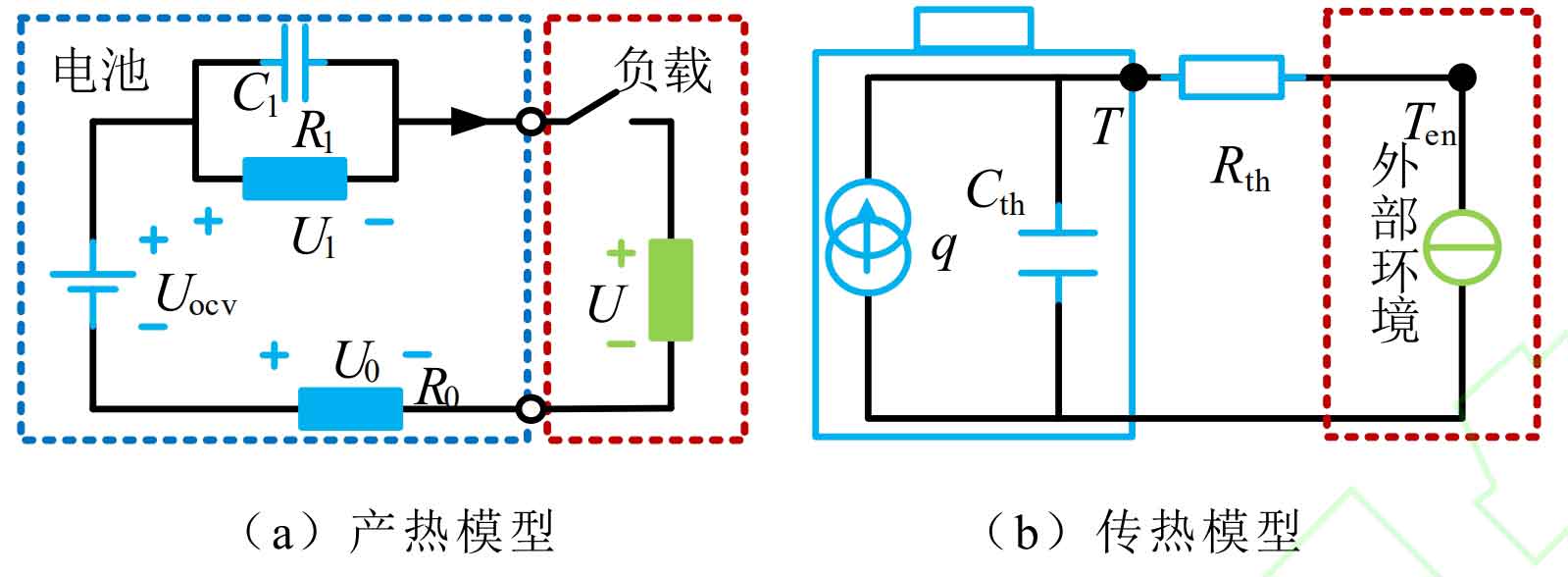
The heat production of a battery can be calculated using a heat generation model, as shown in Figure 2 (a). R0, R1, and C1 are the ohmic internal resistance, polarization internal resistance, and polarization capacitance of the battery, respectively. During charging and discharging, the current flows through the resistance to generate heat, which is composed of reversible heat, irreversible heat, and side reaction heat. The side reaction heat only occurs above 90 ℃, including SEI film decomposition heat, positive and negative pole decomposition heat, etc. This article considers that there is no side reaction heat when the battery operates normally. The specified discharge current is positive, and the thermal and electrical power of the battery can be expressed as:
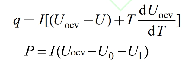
In the formula, q and P are the thermal power and electrical power of the battery, UOCV, U0, U1, and U are the OCV, ohmic voltage, polarization voltage, and load terminal voltage of the battery, I is the battery current, and T is the battery temperature.
2) Battery heat transfer model
The heat transfer model of the battery is shown in Figure 2 (b). The battery generates heat during charging and discharging, mainly through thermal convection with the surrounding environment to complete heat exchange. If the ambient temperature is higher than the battery temperature, the battery temperature will increase, and vice versa, the battery temperature will decrease. The heat exchange relationship is expressed as:
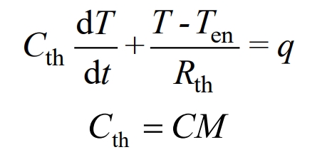
In the formula, Rth and Cth are the thermal resistance and heat capacity of the battery, C and h are the specific heat capacity and convective heat transfer coefficient of the battery, M is the weight of the battery, s is the surface area of the battery, and Ten is the ambient temperature.
1.3 Convex battery electrothermal coupling model
Firstly, based on the battery size and experimental identification of the battery specific heat capacity, convective heat transfer coefficient, temperature battery capacity curve, internal resistance curve of the battery at different temperatures and SOC, and SOC-OCV curve at different temperatures, a battery simulation model is built in finite element software to verify the accuracy of the simulation model in fitting the battery temperature rise.
Then, in the simulation model, the thermal power and electrical power expressions of the battery are set as formulas, and the electrical power and thermal power values of the battery under different currents are simulated. Based on the simulation data, the original electrothermal coupling model is convex, that is, the relationship between electrical power thermal power current is segmented and analyzed, expressed as:
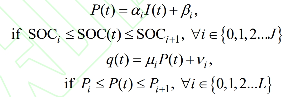
In the formula, P (t), q (t), and I (t) respectively represent the battery electrical power, thermal power, and current during time t, α I β I μ I ν I is the parameter, SOCi and SOCi+1 are the SOC segmentation points, Pi and Pi+1 are the electrical power segmentation points, J and L are the maximum number of SOC and electrical power segmentation points.
Due to factors such as battery materials and manufacturing processes, battery manufacturers limit the battery current at different temperatures, expressed as:
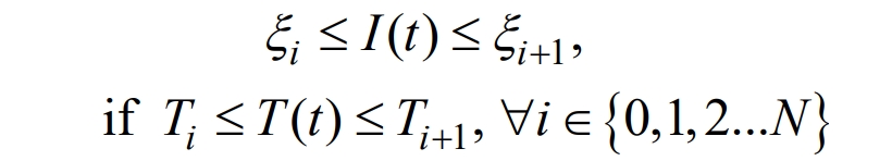
In the formula, T (t) is the battery temperature during time t, ξ I ξ I+1 is the parameter, Ti and Ti+1 are the temperature segmentation points of the battery, and N is the maximum number of segmentation points.
When the battery temperature is too high or too low, the output current of the battery is limited, resulting in limited output power. At the same time, different thermal power sizes lead to different rates of temperature changes in the battery. The comprehensive formula can fully reflect the limiting effect of temperature on the current, thermal power, and electrical power of a single battery.
For each sampling interval, discretize the temperature calculation of the battery according to the formula, and estimate the temperature of the battery for each time period. The battery temperature can be expressed as:
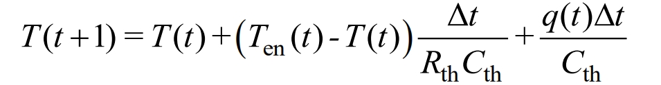
In the formula, T (t+1) and T (t) represent the battery temperature during time t+1 and time t, while Ten (t) represents the ambient temperature during time t, Δ T is the duration of the t period.
2. IES and battery energy storage operation model
2.1 Composition of IES system
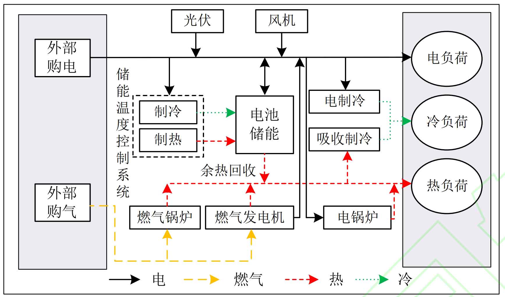
The structure configuration and energy flow of IES are shown in Figure 3. Mainly including photovoltaic cells (PV), wind turbines (WT), battery energy storage (including waste heat recovery) (BES), energy storage temperature control system (TC), gas boilers (GB), gas turbines (GT), electric chillers (EC) Absorption chiller (AC) and electric boiler (EB); Energy forms include electricity and gas; The types of loads include electrical, cooling, and heating loads.
2.2 IES device operation model
1) Gas generator
As a dispatchable power generation unit, gas generators have stable output power. Under the premise of meeting power generation requirements, the heat generated can be provided to IES, thereby improving energy utilization efficiency. The model is represented as:
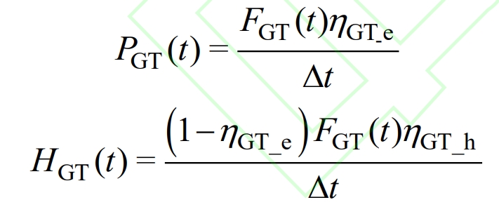
In the formula, PGT (t) and HGT (t) respectively represent the electromechanical power and thermal power of the gas generator during time t, while FGT (t) represents the gas consumption of the gas generator during time t, η GT_ E η GT_ H refers to the power generation and heating efficiency of gas generators.
2) Gas boilers and electric boilers
Gas boilers consume gas to generate heat, while electric boilers consume electrical energy to generate heat. The heat provided by both is related to their respective heating efficiency.
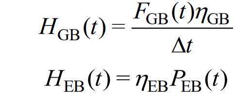
In the formula, HGB (t) is the thermal power of the gas boiler during period t, and FGB (t) is the gas consumption of the gas boiler during period t, η GB refers to the heating efficiency of gas boilers; PEB (t) and HEB (t) respectively represent the electrical power consumed and thermal power generated by the electric boiler during time t, η EB is the heating efficiency of the electric boiler.
3) Absorption refrigeration and electric refrigeration
Absorption refrigeration converts excess heat energy in the system into cold energy, while electric refrigeration consumes electrical energy for refrigeration. The cold energy provided by both is related to their respective refrigeration efficiency.
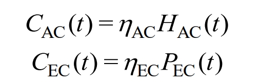
In the formula, HAC (t) and CAC (t) represent the thermal power consumed by the absorption chiller and the cold power generated during the t period, respectively, η AC is the refrigeration efficiency of absorption refrigeration; PEC (t) and CEC (t) represent the electrical power consumed and the cooling power generated by the electric refrigerator during the time period t, η EC is the refrigeration efficiency of the electric refrigerator.
2.3 Battery Energy Storage Operation Model and Its Control
The battery energy storage model is required by IES to reflect the energy storage, temperature control, temperature power output capacity, temperature life loss and other relationships of energy storage when conducting day ahead scheduling optimization.
1) Energy storage
SOC is a parameter that measures the remaining energy of battery energy storage. If the SOC between individual batteries is maintained through control algorithms, the SOC of battery energy storage is consistent with that of individual batteries, including:
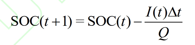
In the formula, SOC (t+1) and SOC (t) represent the battery energy storage SOC at the beginning of the t+1 and t periods, respectively, and Q represents the individual battery charge.
2) Temperature control
The cooling of battery energy storage is achieved through three channels: convective heat dissipation with the environment, partial heat removal by the waste heat recovery system, and cooling by the temperature control system; Heating is achieved through three channels: convective heating with environmental heat, heat generation from battery charging and discharging, and heating by temperature control systems. Among them, the waste heat recovery system circulates condensed water to remove some of the heat from the battery energy storage bin and merges it into the IES thermal power bus; The temperature control system consumes electrical energy, cools or heats the battery, and maintains a suitable operating temperature for battery energy storage. The model of waste heat recovery and temperature control system is represented as:
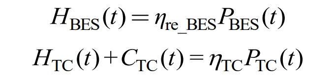
In the formula, HBES (t) is the thermal power of waste heat recovery, η Re_ BES is the efficiency of waste heat recovery; PTC (t), HTC (t), and CTC (t) represent the electrical power consumption, thermal power, and cold power generated by the temperature control system during time t, η TC is the efficiency of the temperature control system.
If the temperature of all individual batteries in the battery energy storage is consistent, then the battery energy storage temperature is consistent with the temperature of the individual batteries. Based on the formula, considering the control of battery energy storage temperature, the battery energy storage temperature is expressed as:
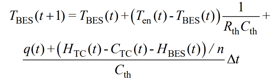
In the formula, TBES (t+1) and TBES (t) represent the battery energy storage temperature during time t+1 and time t, respectively. Ten (t) represents the ambient temperature during time t, and n represents the number of individual batteries in the battery energy storage bin.
3) Temperature power output capability
The output power of battery energy storage is the sum of the output power of all individual batteries, which can be expressed as:

In the formula, PBES (t) is the battery energy storage power during time t. A comprehensive formula can describe the impact of different temperatures on the energy storage power output capacity of batteries.
4) Temperature Life Loss
Research has shown that if the operation of lithium-ion batteries is limited within a certain DOD range to avoid overcharging and discharging, there is a fixed marginal cost of increasing battery DOD. The cost of battery energy storage life loss can be expressed as:
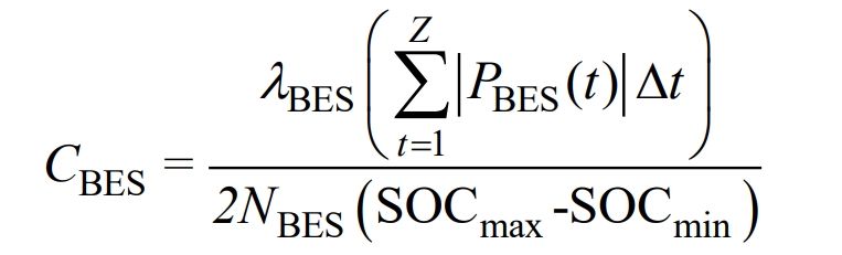
In the formula, CBES is the cost of battery energy storage life loss, λ BES is the battery energy storage price, SOCmax and SOCmin are the upper and lower limits of SOC allowed for battery energy storage charging and discharging, NBES is the number of times the battery energy storage can operate within the SOC range [SOCmin, SOCmax], and Z is the number of scheduling periods.
When the battery temperature is at extreme high or low temperatures, NBES significantly decreases. According to the research data in literature [9], the relationship between NBES and temperature can be segmented and analyzed as follows:
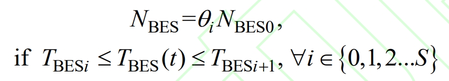
In the formula, NBES0 is the number of cycles of battery energy storage at room temperature (25 ℃), θ I is the parameter, TBESi, TBESi+1 are the temperature segmentation points for battery energy storage, and S is the maximum number of segmentation points.
A comprehensive formula can describe the impact of different temperatures on battery energy storage life loss.
3. IES optimization scheduling for temperature control of battery energy storage
3.1 Objective function
The goal is to minimize the daily operating cost of IES, which includes electricity purchase cost, gas purchase cost, carbon emission cost, battery energy storage life decay cost, and penalty cost for wind and light abandonment, without considering other equipment maintenance costs and depreciation rates. The objective function for optimizing scheduling problems is:
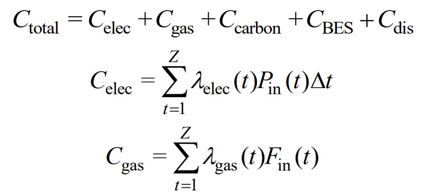
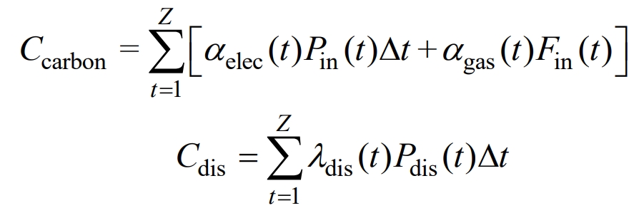
In the formula, Ctotal is the total cost, Celec is the electricity purchase cost, Cgas is the gas purchase cost, Ccarbon is the carbon emission cost, Cdis is the penalty cost for wind and light abandonment, Pin (t) and Fin (t) are the electricity and gas purchased during time t, respectively, and Pdis (t) is the wind and light abandonment during time t, λ Elec (t) λ Gas (t) λ Dis (t) refers to the penalty prices for electricity, gas, wind, and light consumption during period t, α Elec (t) α Gas (t) represents the carbon emission prices of electricity and gas during time t.
3.2 Constraints
During operation, IES mainly meets the constraints of power and energy balance, as well as the operational constraints of various equipment.
1) Power and energy balance constraints
During each period of IES operation, its electrical power, thermal power, cold power, and gas should maintain a supply-demand balance, expressed as:
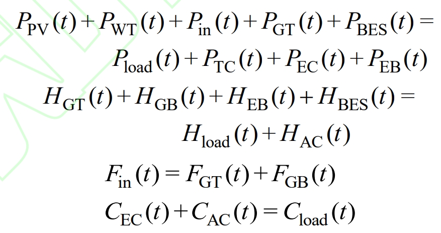
In the formula, PPV (t), PWT (t), Pload (t), Hload (t), and Cloud (t) represent the absorbed photovoltaic power, wind power, and IES power load, thermal load, and cooling load power during time t.
2) Constraints on photovoltaic and wind power equipment
The output of photovoltaic and wind power has volatility, which may result in the abandonment of light and wind. The power consumption of photovoltaic and wind power meets the following constraints:
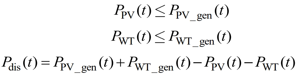
In the formula, PPV_ Gen (t), PWT_ Gen (t) refers to the electrical power generated by photovoltaic and wind power during period t.
3) Battery Energy Storage and Its Temperature Control Constraints
Overcharging or discharging can cause irreversible damage to battery energy storage, exacerbating life decay. It is necessary to limit the SOC range of battery energy storage, and the SOC must remain equal before and after a day of scheduling; The temperature control system needs to meet the maximum output constraint, which is expressed as:
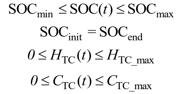
In the formula, SOCinit and SOCend respectively represent the SOC of battery energy storage at the beginning and end of a day’s scheduling; HTC_ Max, CTC_ Max refers to the maximum heating power and maximum cooling power of the temperature control system.
4) Other device constraints
Gas generators, gas boilers, electric boilers, absorption refrigeration, and electric refrigeration equipment must meet the maximum output constraint during operation, expressed as:
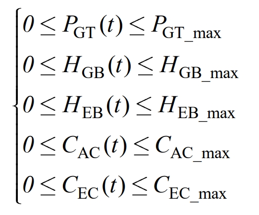
In the equation, PGT_ Max, HGB_ Max, HEB_ Max, CAC_ Max, CEC_ Max refers to the maximum output power of gas generators, gas boilers, electric boilers, absorption refrigerators, and electric refrigerators.
4. Example analysis
4.1 Example Setting
Taking a certain IES as the research object, model it in Matlab and call the Gurobi solver to solve. Number of dispatch segments Z=24, unit dispatch time Δ T=1 h, Δ The output of each equipment within t is constant, and the electricity price follows the time of use electricity price. Considering that the temperature in spring and autumn is suitable, which exacerbates the degradation of battery energy storage life and limits power output capacity, it is not obvious. However, the high temperature in summer and the cold temperature in winter have a significant impact on battery energy storage. Therefore, in the calculation example, the summer and winter seasons are used as examples for analysis. In summer, the gas boiler does not work, and the battery energy storage waste heat recovery works. In winter, the gas boiler operates at full load, and the battery energy storage waste heat recovery does not work.
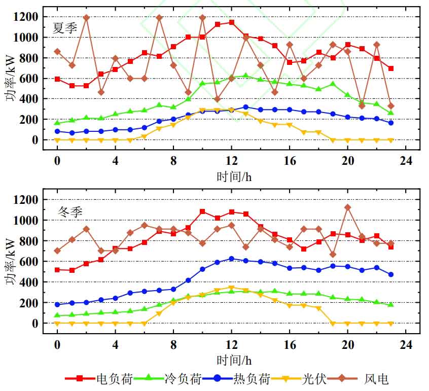
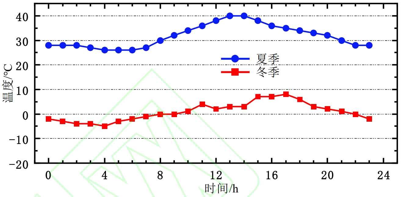
The parameters of the single battery used for battery energy storage are shown in Table 1; The equipment and parameters of IES are shown in Appendix Table 1; The predicted output values of summer and winter cooling, heating and power loads and photovoltaic wind power are shown in Figure 5; When the temperature control system is not used, the typical 24-hour temperature distribution of the battery energy storage bin in summer and winter is shown in Figure 6; The peak and valley prices of electricity prices are 0.144, 0.119, and 0.033 $/kW · h. The electricity prices are divided into peak periods from 9:00 to 11:00, 13:00 to 17:00, normal periods from 8:00 to 9:00, 17:00 to 22:00, and valley periods from 0:00 to 8:00, 11:00 to 13:00, and 22:00 to 24:00; The price of gas is 0.0277 $/(kW · h), the price of battery energy storage is 142.8 $/(kW · h), the carbon emission price is 35.7 $/t, and the carbon emission factors of electricity and gas are 40 and 200 g/(kW · h), respectively.
4.2 Example Results
1) Battery temperature experiment and simulation results
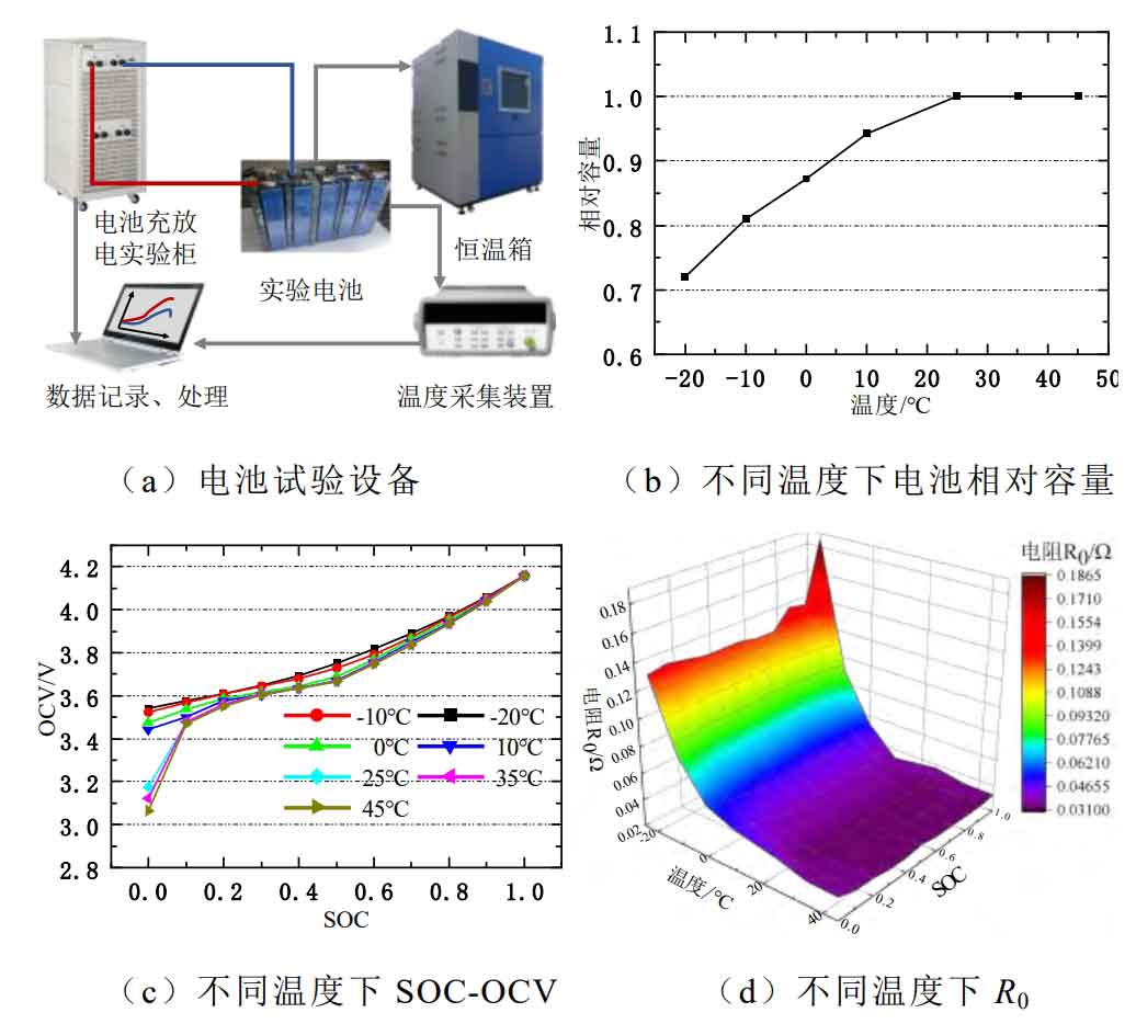
The equipment used for battery characteristic testing is shown in Figure 7 (a). The battery is placed in a constant temperature box and connected to the charging and discharging experimental cabinet through wires. The temperature, current, and voltage data of the battery are collected and summarized for processing. The relative capacity, SOC-OCV curve, and internal resistance R0 of the battery obtained from constant current discharge and pulse discharge experiments at different temperatures are shown in Figure 7 (b), (c), and (d), respectively. In low-temperature environments, the internal resistance of the battery significantly increases, and the battery capacity sharply decreases. Moreover, the SOC-OCV curve is smoother because the battery discharge is incomplete at low temperatures, resulting in a larger OCV at SOC of 0.
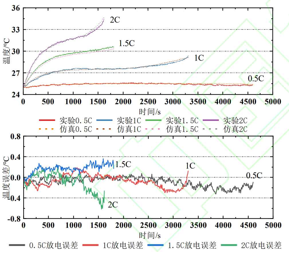
Establish a finite element simulation model in COMSOL based on the experimental parameters. Conduct temperature rise experiments on batteries at 0.5 C, 1 C, 1.5 C, and 2 C in a 25 ℃ incubator, and record the battery temperature using thermocouples; Set the battery charging and discharging rate and environmental temperature in COMSOL to be consistent with the experiment, and predict the temperature change of the battery. The absolute values of battery temperature and their errors obtained from temperature rise experiments and simulations as a function of discharge time are shown in Figure 8. From Figure 8, it can be seen that the error of fitting the battery temperature to the battery simulation model established based on the parameters obtained from the battery characteristics experiment and the electrothermal coupling model is within 0.6 ℃.
| Parameters | Value |
| Rated capacity | 4 Ah |
| Rated voltage | 3.65 V |
| Cut-off voltage | 4.2 V/2.65 V |
| Working temperature | Charging 0 ℃~45 ℃ Discharge -20 ℃~60 ℃ |
| Maximum charging current | 0 ℃ ≤ T ≤ 5 ℃ (0.4 A) 5 ℃ ≤ T ≤ 15 ℃ (0.8 A) 0 ℃ ≤ T ≤ 45 ℃ (2 A) |
| Maximum discharge current | -20 ℃ ≤ T ≤ 5 ℃ (4 A) 5 ℃ ≤ T ≤ 45 ℃ (12 A) 45 ℃ ≤ T ≤ 60 ℃ (6 A) |
| Battery thermal resistance Rth | 5.98 K/W |
| Battery heat capacity Cth | 96.6 J/K |
2) Analysis of IES Day ahead Scheduling Optimization Results
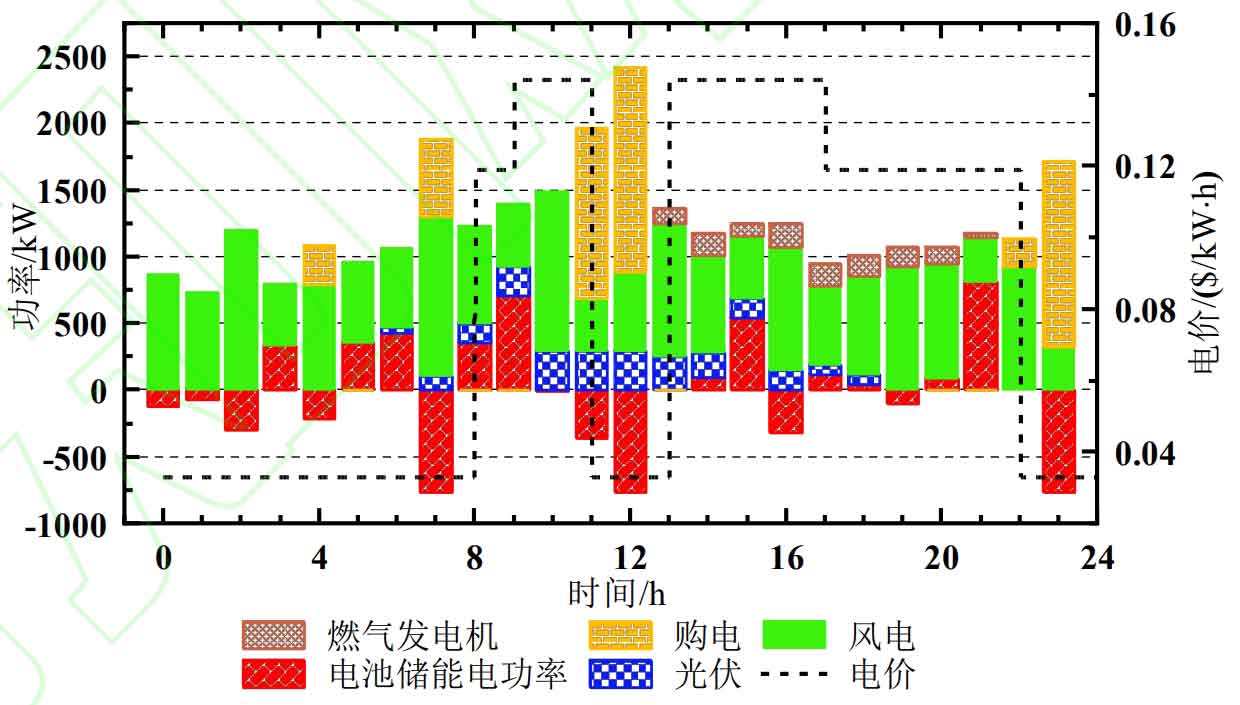
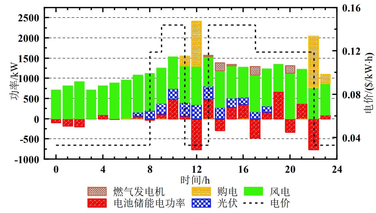
The optimization results of IES electrical load in summer are shown in Figure 9. In the early morning (0:00-3:00), the battery is charged for energy storage. This is because during this period, the electrical load is small and the wind power output is high. The excess wind power output is used to charge the battery for energy storage, thus avoiding wind abandonment; At noon (11:00-13:00), the increase in IES electricity purchase is due to the low electricity price period during which the battery can be stored and charged; Late at night (23:00-24:00), IES increased its electricity consumption by 1183 kW · h due to the need to charge the battery to the initial SOC, resulting in an increase in electricity demand.
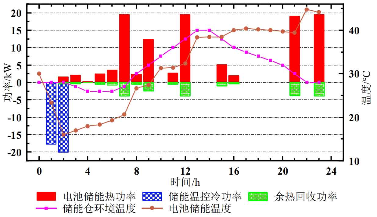
The optimization results of summer battery energy storage temperature are shown in Figure 10. The energy storage temperature control system operates in the early morning (1:00-3:00), reducing the battery temperature to below 20 ℃. As the heat generated during battery charging and discharging and the environmental temperature of the energy storage warehouse is affected, the battery energy storage temperature gradually increases; The temperature of battery energy storage has experienced several sharp increases (7:00-8:00, 11:00-12:00), because when the battery energy storage power is high, the heat generation power is correspondingly high, resulting in an increase in battery temperature; The waste heat recovery of battery energy storage takes away some of the battery heat, which is then fed into the system’s thermal power transmission bus to meet the IES thermal load requirements.
The optimization results of winter IES electrical load are shown in Figure 11. The reason for battery energy storage and charging in the early morning (0:00-3:00) is because during this period, the electrical load is small and the wind power output is high. The excess wind power output provides energy storage and charging for the battery, avoiding wind abandonment; At noon (12:00-13:00), IES purchased 868.12 kW · h more electricity due to the low electricity price period during which batteries are stored and charged.
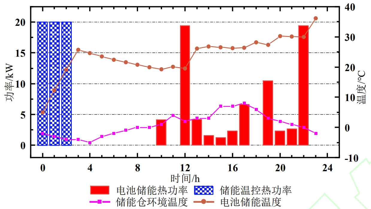
The optimization results of winter battery energy storage temperature are shown in Figure 12. The temperature control system operates in the early morning (0:00-3:00), heating the battery energy storage temperature to above 20 ℃; Due to the low ambient temperature of the battery energy storage bin, the temperature of the battery energy storage gradually decreases, and the temperature of the battery energy storage increases during the time period (12:00-13:00, 22:00-23:00); To maintain the temperature of battery energy storage, the waste heat recovery system is not working.
3) Comparative analysis of optimization results using different methods
Compare the method proposed in this article with the method without battery energy storage temperature control from three aspects: IES economy, battery energy storage thermal safety, and battery energy storage utilization rate.
Method 1: The method proposed in this article includes temperature control (temperature control system, waste heat recovery system)
Method 2: Traditional analysis method, excluding temperature control (temperature control system, waste heat recovery system)
In terms of IES economy, compare the daily operating costs of IES under two methods. The comparison of summer costs is shown in Table 2. Compared to Method 2, the total cost of Method 1 decreased by 6.72%. Specifically, Method 1 consumes electrical energy during the operation of the temperature control system, increasing the electricity cost by 0.46 $; The temperature control adjusts the battery energy storage temperature, reducing the battery loss cost by $22.81; Part of the battery energy storage waste heat recovery meets the system’s thermal load, reducing gas costs by $3.59 and carbon emission costs by $0.89.
| Method 1 | Method 2 | |
| Electricity cost/$ | 173.79 | 173.03 |
| Natural gas costs/$ | 108.16 | 111.75 |
| Carbon emission cost/$ | 35.41 | 36.30 |
| Battery loss cost/$ | 50.85 | 73.66 |
| Cost of abandoning wind and light/$ | 0 | 0 |
| Total cost/$ | 368.21 | 394.74 |
The comparison of winter costs is shown in Table 3. Compared to Method 2, the total cost of Method 1 decreased by 13.78%. Specifically, the temperature control system of Method 1 increased electricity consumption, and Method 1 used more electricity while Method 2 used more gas, resulting in an increase of 9.98 $in electricity costs for Method 1; Method 1: The temperature control system adjusts the battery energy storage temperature to reduce the battery loss cost, thereby reducing the battery loss cost by 45.93 $; Method 1: Battery energy storage operates at a suitable temperature, with higher charging and discharging power, which can absorb more solar and solar output. However, Method 2: Battery energy storage operates at a low temperature and cannot fully absorb solar and solar output, resulting in a cost of wind and solar abandonment. Therefore, Method 1 reduces the cost of wind and solar abandonment by $12.55 and the cost of carbon emissions by $2.41.
| Method 1 | Method 2 | |
| Electricity cost/$ | 93.94 | 83.96 |
| Natural gas costs/$ | 214.55 | 225.58 |
| Carbon emission cost/$ | 59.39 | 61.80 |
| Battery loss cost/$ | 20.02 | 65.95 |
| Cost of abandoning wind and light/$ | 0 | 12.55 |
| Total cost/$ | 387.90 | 449.84 |
In terms of thermal safety of battery energy storage, compare the duration of battery energy storage operating in an appropriate temperature range (10 ℃~40 ℃) throughout the day under two methods; In terms of battery energy storage utilization rate, compare the total energy of battery energy storage during full day charging and discharging under two methods. The comparison between the thermal safety and utilization of battery energy storage is summarized in Table 4. Compared to Method 2, the duration of Method 1 operating in the appropriate temperature range increased by 120% in summer and 450% in winter; The total energy of charging and discharging increased by 23.13% in summer and 30.71% in winter.
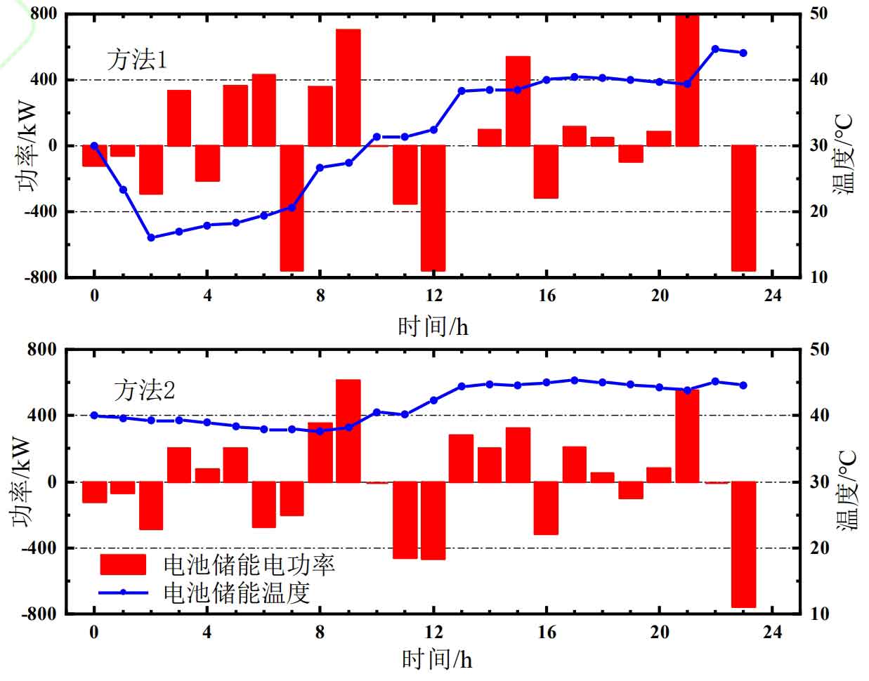
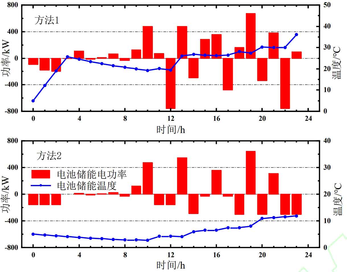
Analyzing the reasons, Method 1 maintains the appropriate operating temperature of the battery by controlling its energy storage temperature, resulting in a longer duration of battery energy storage in the appropriate temperature range throughout the day; The appropriate working temperature improves the battery’s energy storage power output capacity, so the total energy of charging and discharging throughout the day is more. The specific output and temperature of battery energy storage in summer and winter are shown in Figures 13 and 14. It can be seen that in Method 2, the battery energy storage temperature is higher than 40 ℃ from 12:00 to 24:00 in summer, and lower than 10 ℃ from 0:00 to 20:00 in winter.
| Summer suitable temperature time/h | Total energy of summer charging and discharging/kW · h | Winter suitable temperature time/h | Total energy of winter charging and discharging/kW · h | |
| Method 1 | 22 | 7 630.69 | 22 | 6 420.94 |
| Method 2 | 10 | 6 197.29 | 44 | 912.22 |
5. Conclusion
In response to the problem of rapid life decay and poor performance of battery energy storage under extreme high and low temperatures, this paper proposes a temperature power characteristic model for battery energy storage and an IES low-carbon economic scheduling method with temperature control. The proposed method is validated through numerical examples, and the conclusions are as follows:
1) Convex the battery electrothermal coupling model, estimate the battery temperature based on this model, and quantify the battery energy storage temperature power output capacity. By controlling the battery energy storage temperature and output power, avoid excessive charging and discharging damage to the battery under extreme high and low temperatures. After calculation, compared to not considering the temperature control of battery energy storage, the method proposed in this paper can reduce the cost of battery energy storage life loss by 30.97% and 69.64% on typical days in summer and winter.
2) Based on the characteristics of battery energy storage temperature power output capacity, a low-carbon economic scheduling strategy for IES with battery energy storage temperature control is proposed. By controlling the battery energy storage temperature, the power output capacity is improved, thereby improving new energy consumption and reducing IES operating costs. After calculation, compared to not considering battery energy storage temperature control, the method proposed in this paper can reduce the operating cost of IES by 6.72% and 13.78% on typical days in summer and winter.
Tab. Equipment and parameters of IES
| Device Name | Parameter | Numerical value |
| Gas generator | Number of units | 1 |
| Gas generator | Power generation efficiency η GT_ E | 0.3 |
| Gas generator | Heating efficiency η GT_ H | 0.73 |
| Gas generator | Rated electrical power PGT_ Max/kW | 200 |
| Gas boiler | Number of units | 1 |
| Gas boiler | Heating efficiency η GB | 0.85 |
| Gas boiler | Rated thermal power HGB_ Max/kW | 200 |
| Electric cooker | Number of units | 4 |
| Electric cooker | Heating efficiency η EB | 0.91 |
| Electric cooker | Rated power HEB_ Max/kW | 200 |
| Electric refrigerator | Number of units | 2 |
| Electric refrigerator | Refrigeration efficiency η EC | 3.00 |
| Electric refrigerator | Rated cooling power CEC_ Max/kW | 300 |
| Absorption refrigerator | Number of units | 2 |
| Absorption refrigerator | Refrigeration efficiency η AC | 0.80 |
| Absorption refrigerator | Rated cooling power CAC_ Max/kW | 400 |
| Battery energy storage and temperature control system | Number of modules connected in series with batteries | 10 |
| Battery energy storage and temperature control system | Number of modules connected in series with batteries | 10 |
| Battery energy storage and temperature control system | Number of modules | 1000 |
| Battery energy storage and temperature control system | Maximum State of Charge (SOC) max | 0.9 |
| Battery energy storage and temperature control system | Minimum State of Charge (SOC) min | 0.1 |
| Battery energy storage and temperature control system | Initial State of Charge SOCinit | 0.6 |
| Battery energy storage and temperature control system | Normal temperature cycling frequency NBES0 | 8000 |
| Battery energy storage and temperature control system | Temperature control system efficiency η TC | 3.00 |
| Battery energy storage and temperature control system | Temperature controlled rated thermal power HTC_ Max/kW | 20 |
| Battery energy storage and temperature control system | emperature controlled rated cooling power CTC_ Max/kW | 20 |
| Battery energy storage and temperature control system | Waste heat recovery efficiency η Re_ BES | 0.2 |
| wind power generation | Number of units | 8 |
| wind power generation | Maximum output power/kW | 180 |