
As the global energy landscape transitions toward sustainability, the role of advanced energy storage system technologies in modern power grids has become increasingly critical. In my recent research, I have focused on the electromagnetic transient (EMT) simulation of two prominent topological configurations for sodium-ion battery-based energy storage system: the centralized architecture and the string-configured architecture. This paper details my simulation methodology, model construction, and comparative analysis of dynamic responses under various grid disturbance scenarios. The objective is to provide a quantitative basis for topology selection in practical sodium-ion energy storage system deployments.
Sodium-ion batteries have emerged as a promising alternative to lithium-ion batteries due to the abundant availability of sodium resources, superior wide-temperature performance, and enhanced safety characteristics. While extensive research has been dedicated to material science and cell-level optimization, the system-level integration and performance evaluation of different topologies remain relatively underexplored. My work addresses this gap by developing comprehensive EMT models for both centralized and string configurations of a sodium-ion energy storage system.
System Topology and Architecture
The centralized topology in a sodium-ion energy storage system involves grouping a large number of battery cells into one or more high-capacity battery clusters via series-parallel connections. These clusters are then connected in parallel on the DC side to a single, large-capacity Power Conversion System (PCS). This architecture is characterized by its high energy density, simple electrical layout, and lower initial capital expenditure. However, it imposes stringent requirements on cell consistency. Any performance degradation or failure in a single cell can affect the entire cluster, and the parallel connection of clusters can lead to circulating currents, impacting both efficiency and safety.
In contrast, the string-configured topology adopts a more modular approach. Here, the battery cells are divided into smaller, independent modules or sub-units. Each sub-unit (battery cluster) is connected to its own dedicated, smaller-capacity PCS. The outputs of these multiple PCS units are then aggregated on the AC side, as shown in the conceptual overview below. This architecture offers high redundancy and scalability. A fault in one module has a minimal impact on the overall system operation. It also allows for flexible power distribution and optimized performance through individual module monitoring.
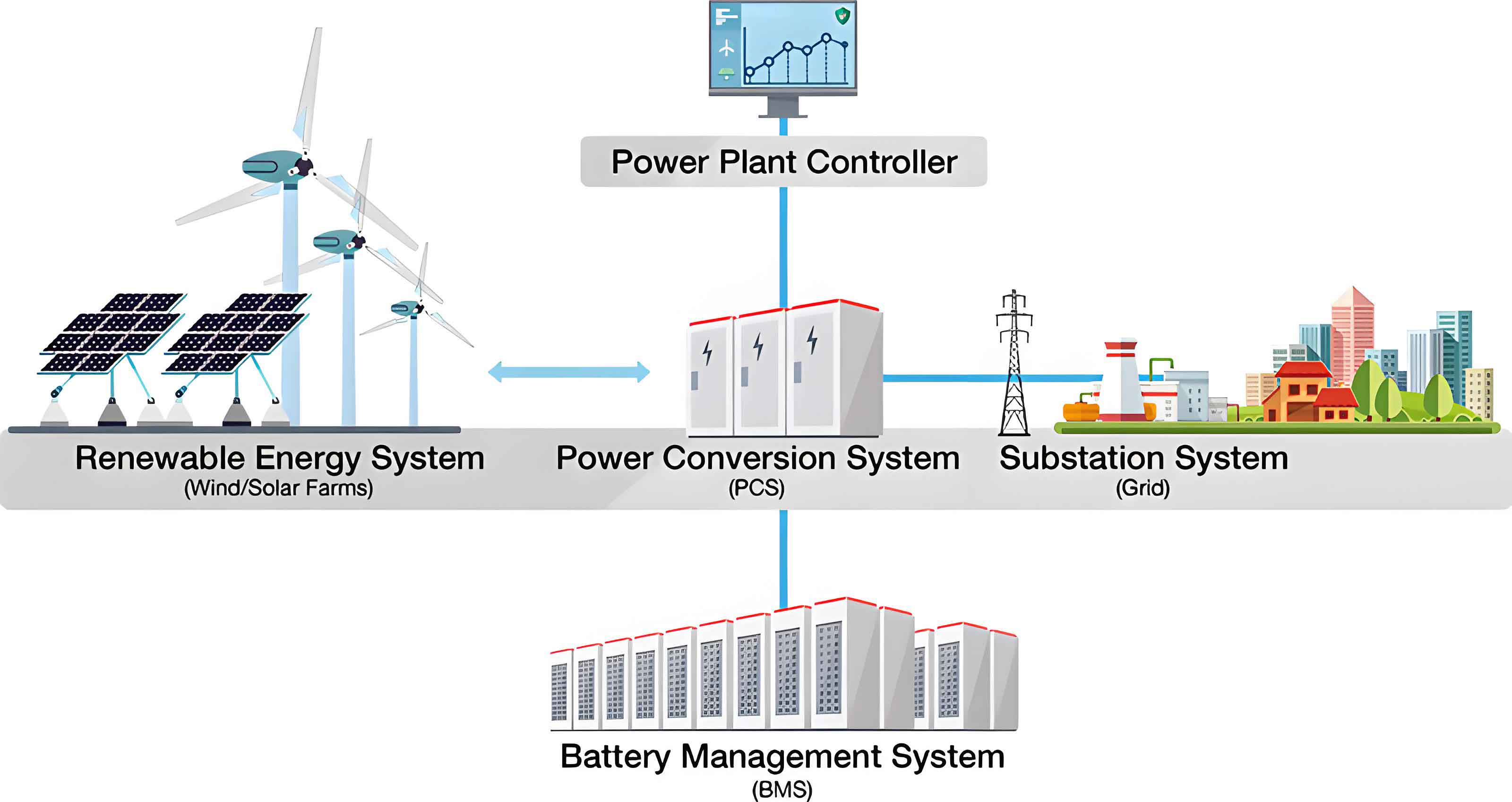
Based on my analysis, the following table summarizes the key architectural differences between the two topologies for a sodium-ion energy storage system.
| Feature | Centralized Topology | String Topology |
|---|---|---|
| DC Side Connection | Multiple battery clusters in parallel | Single cluster per PCS |
| PCS Configuration | Single, large-capacity PCS | Multiple, smaller-capacity PCS units |
| System Redundancy | Low; fault can affect large capacity | High; fault isolated to one module |
| Scalability | Lower; requires reconfiguration | High; plug-and-play modules |
| Circulating Current Risk | High | Low |
| Dynamic Control Flexibility | Moderate | High |
| Initial Cost | Lower | Higher |
| Maintenance Complexity | High (system-level shutdown) | Low (module-level replacement) |
Electromagnetic Transient Model Construction
To quantify the dynamic response characteristics of these two topologies, I constructed detailed EMT models using the PSCAD V5.0 simulation platform. The model is composed of two main parts: the battery equivalent circuit and the PCS model.
Sodium-Ion Battery Model
For the simulation of the energy storage system, I selected an improved Thevenin equivalent circuit model for the sodium-ion battery. This model balances accuracy and computational efficiency, making it suitable for power system studies. The model includes a voltage source representing the open-circuit potential (E), an internal resistance (R₀), and an RC parallel network (R, C) to simulate the polarization effects. The state equation for this model is crucial for accurate dynamic representation.
The terminal voltage of the battery cell can be expressed as:
$$ V_{cell} = E – I_{cell} \cdot R_0 – V_p $$
where \( V_p \) is the voltage across the polarization RC network. The dynamics of the polarization voltage are governed by:
$$ \frac{dV_p}{dt} = \frac{I_{cell}}{C} – \frac{V_p}{R \cdot C} $$
This model effectively captures the nonlinear transient behavior of sodium-ion cells during charge and discharge pulses.
Power Conversion System and Control Model
The PCS is the critical interface between the battery and the grid. For my simulation of the sodium-ion energy storage system, I modeled a three-level, neutral-point-clamped (NPC) topology. The main circuit includes DC-link capacitors, IGBT switches with detailed turn-on/turn-off losses, and an LCL filter for AC-side harmonic attenuation.
The control strategy is based on a dual-loop structure in the synchronous rotating dq reference frame. The outer loop is a power control loop that generates reference currents based on active and reactive power commands (\( P_r, Q_r \)) and grid support requirements. The inner loop is a current control loop employing PI controllers for fast tracking. For grid code compliance, the model includes fault ride-through (FRT) control logic that dynamically adjusts the current reference to support voltage recovery during low or high voltage events. A negative-sequence current suppression loop is also implemented to handle unbalanced grid faults.
The core voltage equations for the PCS in the dq-frame are:
$$ u_d = R \cdot i_d + L \frac{di_d}{dt} – \omega L i_q + u_{gd} $$
$$ u_q = R \cdot i_q + L \frac{di_q}{dt} + \omega L i_d + u_{gq} $$
Decoupling and feedforward terms are used to achieve independent control of \( i_d \) (active current) and \( i_q \) (reactive current). The modulation waves for the PWM generator are derived from the PI controller outputs.
Simulation Results and Comparative Analysis
I conducted three distinct simulation scenarios to compare the performance of the centralized and string topologies for the sodium-ion energy storage system. The base parameters used for the models are listed in the table below.
| Parameter | Value |
|---|---|
| Single Cell Capacity | 210 Ah |
| Cells per Cluster | 384 |
| Number of Clusters | 14 |
| Centralized PCS Rated Power | 1680 kW |
| String PCS Rated Power | 120 kW (per unit, 14 units total) |
| DC Link Voltage | 1.5 kV |
| AC Grid Voltage | 690 V |
Scenario 1: Low Voltage Ride-Through (LVRT)
In this test, the energy storage system was initially operating in discharge mode at 20% of rated power. A three-phase fault was applied, causing the grid voltage at the point of common coupling to drop to 20% of its nominal value. My simulation recorded the response of positive-sequence voltage, active power, reactive power, and currents. Both topologies successfully rode through the fault, injecting reactive current to support grid voltage recovery as required by grid codes. The transient waveforms showed nearly identical behavior for both configurations. This demonstrates that the control logic, rather than the topology, is the dominant factor during severe symmetrical faults.
Scenario 2: High Voltage Ride-Through (HVRT)
A similar test was performed for an overvoltage event. The energy storage system was again at 20% power discharge when the grid voltage swelled to 130% of the nominal value. Both the centralized and string topologies responded by rapidly reducing active power output and absorbing reactive power to limit the voltage rise. The response times and the transient overshoot were practically identical for both structures. This confirms the robustness of the control strategies implemented in the PCS models.
Scenario 3: Dynamic Power Response (Step Change)
To evaluate the dynamic performance during normal operation, I simulated a step change in the active power command. Starting from zero, the energy storage system was commanded to ramp up to its rated power in discharge mode. The results showed a clear distinction between the two topologies. The key performance indicators from this simulation are summarized in the table below.
| Performance Metric | Centralized Topology | String Topology |
|---|---|---|
| Rise Time (10% to 90%) | ~120 ms | ~45 ms |
| Settling Time (to within 2%) | ~250 ms | ~100 ms |
| Overshoot | ~8% | ~5% |
The string topology demonstrated a significantly faster rise time and settling time. This advantage stems from the modular nature of the architecture. When the total power command is dispatched, the aggregate output is the sum of the responses from 14 independent PCS units acting concurrently. This parallel processing allows for a much swifter aggregate power change compared to the single, larger PCS in the centralized topology. The faster response is a critical advantage for providing grid ancillary services like fast frequency response.
The mathematical representation of this aggregate response can be approximated. If each of the \( n \) string PCS units has a transfer function \( G_{string}(s) \), the overall response is \( n \times G_{string}(s) \) operating in parallel. The centralized system, with one large PCS, has a transfer function \( G_{central}(s) \). The time constant of \( G_{central}(s) \) is typically larger due to the larger DC-link capacitance and filtering components required to manage the high power. A simplified first-order approximation for the response time (\( \tau \)) shows:
$$ \tau_{central} \propto \frac{C_{DC,central}}{P_{rated}} $$
$$ \tau_{string} \propto \frac{C_{DC,string}}{P_{rated,string}} $$
Since \( C_{DC,central} \) is much larger than an individual \( C_{DC,string} \), and the power rating per unit is smaller, the string topology inherently has a lower time constant and faster dynamic response.
Discussion and Conclusions
My extensive EMT simulations of the sodium-ion energy storage system provide clear, quantitative insights into the behavior of centralized and string topologies. The results confirm that for standard grid code requirements like LVRT and HVRT, the performance is primarily determined by the PCS control algorithms. Both topologies exhibit comparable robustness and compliance capabilities under severe grid disturbances. The control logic for fault ride-through and voltage support, which I implemented in the models, functioned effectively regardless of the DC-side configuration.
However, the critical differentiator is the dynamic response during normal power commands. The string topology of the energy storage system offers a substantial advantage in speed. Its modular, multi-PCS architecture allows for rapid aggregate power changes. This makes it exceptionally well-suited for applications requiring fast ramping, such as frequency regulation and smoothing of intermittent renewable generation. The centralized topology, while simpler and potentially more cost-efficient upfront, lags in transient responsiveness.
In conclusion, the choice between a centralized and a string topology for a sodium-ion energy storage system should be carefully weighed based on the primary application. If the system is primarily designed for bulk energy shifting and slow grid support, the centralized topology’s lower initial cost may be favorable. For applications demanding high availability, easy scalability, and superior dynamic performance for ancillary services, the string topology, despite its higher initial investment, offers clear and quantifiable benefits. My future work will focus on integrating these simulation findings with an economic analysis, considering factors like lifecycle costs, maintenance, and revenue from fast-response grid services, to provide a holistic framework for topology selection in practical sodium-ion energy storage system projects.