
The evolution of modern power systems is increasingly characterized by complex, interconnected hybrid AC/DC grids. While Modular Multilevel Converter-based High-Voltage Direct Current (MMC-HVDC) transmission offers significant advantages over traditional Line-Commutated Converter (LCC) technology, such as eliminating commutation failure and providing independent control of active and reactive power, it does not fully decouple the interconnected AC systems. A critical challenge persists: strong active power coupling between the AC and DC sides. A fault or disturbance on one side inevitably propagates to the other, threatening the stability and security of the entire hybrid network. For instance, an AC fault at the sending end can disrupt power flow to the receiving end DC system, and conversely, a DC fault can cause significant power imbalances and instability on the connected AC grids. To realize the ideal “firewall” functionality of HVDC links and enable their truly independent and resilient operation, it is essential to break this inherent active power dependency.
Integrating energy storage directly into the converter topology presents a transformative solution. This article explores the application of a cell energy storage system integrated within the MMC structure (BESS-MMC) for HVDC applications. The core principle is to use the cell energy storage system to provide instantaneous power buffering. By compensating for the power difference between the AC-side input and the DC-side output, the cell energy storage system enables decoupled control, allowing power transmission on one side to continue seamlessly even during severe disturbances on the other. This discussion will cover the system’s topology, its decoupling working principle, a detailed electromagnetic transient (EMT) modeling methodology suitable for large-scale HVDC simulation, and validation through comprehensive case studies.
Topology and Operating Principle of the BESS-MMC-HVDC System
The fundamental topology of a BESS-MMC-HVDC station is an extension of the standard MMC. It consists of three phase units, each comprising upper and lower arms. Each arm contains a series connection of N submodules (SMs) and an arm inductor \(L_0\). The pivotal innovation lies within the submodule design. Each SM integrates a battery cell energy storage system via a DC/DC converter into the conventional half-bridge structure.
The power flow relationship within a BESS-MMC station is governed by the following equations, assuming ideal lossless conversion:
$$P_{ac} + P_{BESS} = P_{dc}$$
$$P_{ac} = \sqrt{3} V_{ac} I_{ac} \cos \phi$$
$$P_{dc} = V_{dc} I_{dc}$$
Where \(P_{ac}\), \(P_{dc}\), and \(P_{BESS}\) are the AC-side power (positive into converter), DC-side power (positive out of converter), and power of the cell energy storage system (positive when discharging), respectively. \(V_{ac}\), \(I_{ac}\), and \(\phi\) are the AC line voltage, current, and power factor angle. \(V_{dc}\) and \(I_{dc}\) are the DC-link voltage and current.
In normal steady-state operation with balanced power flow (\(P_{ac} = P_{dc}\)), the cell energy storage system is idle, and \(P_{BESS} = 0\). The control strategy for the BESS-MMC’s main converter mirrors that of a standard MMC, typically involving vector control in a dq-reference frame for regulating active/reactive power or AC voltage.
The decoupling capability arises during disturbances. Consider an AC-side fault at the sending-end station causing a sudden drop in \(P_{ac}\). To maintain the scheduled DC power \(P_{dc}\), the required power deficit is supplied by the cell energy storage system discharging: \(P_{BESS} = P_{dc} – P_{ac} > 0\). Conversely, if a DC-side fault blocks \(P_{dc}\), the incoming AC power \(P_{ac}\) can be absorbed by charging the cell energy storage system: \(P_{BESS} = P_{dc} – P_{ac} < 0\). This active compensation effectively breaks the direct real-time link between AC and DC active power, enabling independent ride-through capabilities. The control of the cell energy storage system is managed locally by the DC/DC converter in each SM, which follows a reference current signal derived from the overall station-level power balancing controller.
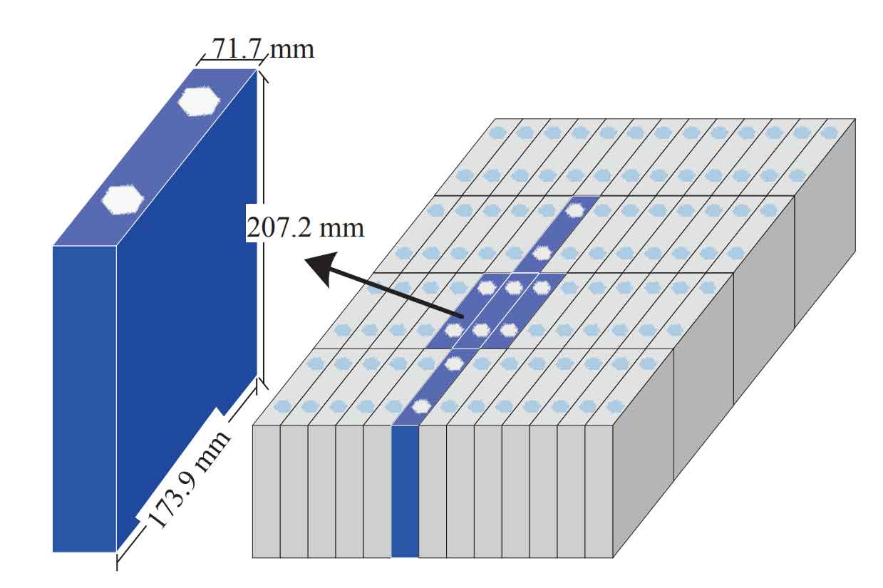
The physical implementation of the cell energy storage system is critical. For HVDC-scale voltages, battery cells are aggregated into modules and strings. For example, a single lithium-ion cell energy storage system unit might be formed by connecting multiple cells in series and parallel to achieve the required voltage and capacity. These units are then integrated into the submodule’s DC link through the bidirectional DC/DC converter, allowing for precise control of charge and discharge currents independent of the SM capacitor voltage fluctuations.
Modeling Methodology for Large-Scale EMT Simulation
Simulating a full-scale BESS-MMC-HVDC system poses a significant computational challenge due to the large number of detailed power electronic switches (IGBTs and diodes). A direct modeling approach would be prohibitively slow. Therefore, an efficient modeling method based on the Nested Fast and Simultaneous Simulation Approach (NFSSA) and Thévenin equivalents is essential.
The core idea is to represent complex groups of components with simple equivalent circuits comprising a resistor and a voltage source in series, thereby drastically reducing the number of network nodes to be solved at each time step.
1. Thévenin Equivalent of a BESS-Enabled Submodule
The first step is to derive the discrete-time companion model for the energy storage elements using the trapezoidal integration rule. For a capacitor \(C\) and an inductor \(L\), the equations at time step \(t\) are:
$$v_C(t) = R_{Ceq} i_C(t) + v_{Ceq}(t-\Delta T)$$
$$v_L(t) = R_{Leq} i_L(t) – v_{Leq}(t-\Delta T)$$
Where the equivalent resistances and history voltage sources are calculated from past values:
$$R_{Ceq} = \frac{\Delta T}{2C}, \quad v_{Ceq}(t-\Delta T) = v_C(t-\Delta T) + R_{Ceq} i_C(t-\Delta T)$$
$$R_{Leq} = \frac{2L}{\Delta T}, \quad v_{Leq}(t-\Delta T) = R_{Leq} i_L(t-\Delta T) + v_L(t-\Delta T)$$
Applying this to all dynamic components in the BESS-SM (capacitors \(C_0\), \(C_{bat}\), and inductor \(L_1\) of the DC/DC converter) and sequentially simplifying the network through series/parallel combinations and star-delta transformations leads to a final, simple two-terminal Thévenin equivalent for the entire submodule.
$$R_{sm,eq}^{(k,i)} = \frac{(R_{C,eq}+R_1)R_2}{R_{C,eq}+R_1+R_2}$$
$$v_{sm,eq}^{(k,i)}(t-\Delta T) = \frac{v_{C,eq}(t-\Delta T) R_2}{R_{C,eq}+R_1+R_2}$$
Where \(R_{sm,eq}^{(k,i)}\) and \(v_{sm,eq}^{(k,i)}\) are the equivalent resistance and history voltage source of the \(i\)-th SM in arm \(k\) (k representing upper ‘p’ or lower ‘n’ arm of phase a, b, or c). The terms \(R_{C,eq}\) and \(v_{C,eq}\) encapsulate the combined dynamics of the SM capacitor and the entire cell energy storage system with its DC/DC converter.
| Component | Description | Equivalent in Model |
|---|---|---|
| IGBT & Diode Pair | Two-state switch | Switching resistor \(R_{on}/R_{off}\) |
| Capacitor \(C_0\) | SM Capacitor | \(R_{C0eq}\), \(v_{C0eq}(t-\Delta T)\) |
| DC/DC Inductor \(L_1\) | BESS Interface Filter | \(R_{L1eq}\), \(v_{L1eq}(t-\Delta T)\) |
| Battery Model | Cell Energy Storage System | Voltage source \(U_{bat}\) with internal resistance \(R_{bat}\) |
| Entire BESS-SM | Fundamental Building Block | Single Thévenin branch: \(R_{sm,eq}^{(k,i)}\), \(v_{sm,eq}^{(k,i)}(t-\Delta T)\) |
2. Arm and Converter-Level Equivalent Model
Since all SMs within an arm are connected in series, the equivalent resistance and voltage source for an entire arm are simply the sums of the individual SM equivalents:
$$R_{arm,eq}^{k} = \sum_{i=1}^{N} R_{sm,eq}^{(k,i)}$$
$$v_{arm,eq}^{k}(t-\Delta T) = \sum_{i=1}^{N} v_{sm,eq}^{(k,i)}(t-\Delta T)$$
This results in a dramatic simplification. A full BESS-MMC phase leg, which originally contains 2N complex submodules, is reduced to a simple circuit with just six Thévenin branches (two per arm) and an AC-side connection point. This model is computationally extremely efficient while accurately representing the aggregated behavior of all semiconductor switches and the distributed cell energy storage system.
Simulation Case Study and Performance Validation
To validate the modeling approach and demonstrate the decoupling capability, a bipolar \(\pm 400\ kV\), \(400\ MW\) point-to-point BESS-MMC-HVDC system was simulated and compared against a conventional MMC-HVDC system without storage. Key system parameters are summarized below.
| Category | Parameter | Value |
|---|---|---|
| MMC Station | Rated AC Voltage | 220 kV |
| Rated DC Voltage | \(\pm 400\ kV\) | |
| Rated Power | 400 MW | |
| SMs per Arm (N) | 200 | |
| SM Capacitance (\(C_0\)) | \(6.67\ mF\) | |
| Arm Inductance (\(L_0\)) | 76 mH | |
| BESS (per SM) | DC/DC Inductor (\(L_1\)) | 6 mH |
| Battery Voltage (\(U_{bat0}\)) | 1 kV | |
| Battery Capacity | Modeled as large capacitor \(C_{bat}\) | |
| Function | Provide active power buffering for decoupling | |
| DC Line | Length | 200 km |
| Protection | DC Circuit Breakers |
Case 1: AC-Side Fault Ride-Through
A solid three-phase-to-ground fault was applied at the sending-end AC bus at \(t=4.0\ s\), cleared after \(100\ ms\). The comparative responses are stark.
Conventional MMC: The AC voltage collapse causes a near-instantaneous drop in AC active power \(P_{ac}\) to near zero. Since there is no buffer, the DC power \(P_{dc}\) must also collapse to match it, leading to a complete interruption of power transmission to the receiving end. The DC voltage and current plummet.
BESS-MMC System: The AC-side power \(P_{ac}\) similarly drops due to the fault. However, the integrated cell energy storage system immediately detects the imbalance. It discharges, injecting power into the DC link to compensate for the lost AC input. The result is that the DC-side power \(P_{dc}\), voltage \(V_{dc}\), and current \(I_{dc}\) are maintained virtually unchanged. The cell energy storage system successfully decouples the DC network from the AC fault, acting as a reliable power source to sustain the scheduled power transfer. The power from the cell energy storage system \(P_{BESS}\) during the fault is positive and equal to \(P_{dc}\).
Case 2: DC-Side Fault Ride-Through
A permanent pole-to-ground DC cable fault was applied at \(t=4.0\ s\). The DC breakers at both ends operate to isolate the line after \(5\ ms\).
Conventional MMC: Upon line isolation, the DC power \(P_{dc}\) falls to zero. With no path for the incoming AC power \(P_{ac}\), and no buffer to absorb it, the AC-side power must also be drastically reduced by converter control to prevent overvoltage and instability, leading to a significant disturbance on the sending-end AC grid.
BESS-MMC System: When the DC line is isolated (\(P_{dc}=0\)), the incoming AC power \(P_{ac}\) has no outlet. The cell energy storage system control shifts to charging mode, absorbing the full AC input power. Consequently, \(P_{ac}\) can remain constant, as the converter continues to operate normally, with the energy being stored in the battery. The AC grid experiences minimal disturbance. Here, \(P_{BESS}\) is negative, absorbing power. This demonstrates the decoupling in the opposite direction, protecting the AC grid from DC-side failures.
The effectiveness of the decoupling can be quantified by a Decoupling Performance Index (\(\eta\)) during a disturbance period \(T\):
$$\eta = \left(1 – \frac{\int_{T} |P_{ac}(t) – P_{dc,ref}| dt}{\int_{T} |P_{ac,dist}(t) – P_{dc,ref}| dt}\right) \times 100\%$$
Where \(P_{dc,ref}\) is the scheduled DC power and \(P_{ac,dist}(t)\) is the disturbed AC-side power. For a perfect decoupler maintaining \(P_{dc} = P_{dc,ref}\), \(\eta = 100\%\). In the simulated AC fault case for the BESS-MMC, \(\eta\) approaches \(100\%\), while for the conventional MMC, it is near \(0\%\).
Discussion and Implications
The integration of a cell energy storage system into the MMC-HVDC topology, coupled with the efficient NFSSA-based modeling approach, presents a paradigm shift for future grid design. The technical implications are profound:
- Enhanced Grid Resilience: The decoupling functionality transforms HVDC links into true “firewalls,” containing faults and preventing cascading failures across interconnected AC systems. This is crucial for networks with high penetration of inverter-based resources.
- Stability Support: Beyond fault ride-through, the fast-response cell energy storage system can provide primary frequency response and damping to both connected AC grids, analogous to a virtual synchronous machine.
- Economic & Sizing Considerations: The required energy capacity of the cell energy storage system is determined by the anticipated duration of the worst-case contingency it is designed to mitigate (e.g., 100-500 ms for fault ride-through, potentially longer for system islanding). While this adds capital cost, it may offset costs associated with grid reinforcement, special protection schemes, or reliability penalties.
- Modeling Efficiency: The presented Thévenin equivalent modeling method is critical for feasibility. It enables detailed EMT studies of large-scale BESS-MMC-HVDC systems—which could have tens of thousands of switching devices—on practical time scales, making design, analysis, and controller validation possible.
The primary challenge remains the cost and lifecycle management of the large-scale battery cell energy storage system. However, with continuing declines in battery prices and the critical need for grid stability services, the BESS-MMC represents a highly synergistic integration of two key modern grid technologies: HVDC and electrochemical storage.
Conclusion
This analysis demonstrates that the incorporation of a cell energy storage system into the MMC-HVDC converter structure is a technically viable and powerful solution to the problem of active power coupling in hybrid AC/DC grids. The proposed system enables bidirectional decoupling: it can maintain DC power transmission during AC-side faults by discharging the storage, and it can maintain AC-side power absorption (thus stabilizing the AC grid) during DC-side faults by charging the storage.
The NFSSA-based modeling technique, which reduces the entire complex converter with its distributed cell energy storage system to a simple network of Thévenin equivalents, provides an accurate and computationally efficient tool for the EMT simulation of such large-scale systems. Case studies on a \(\pm 400\ kV\) model confirm the superior performance of the BESS-MMC over a conventional MMC under both AC and DC fault conditions.
Moving forward, the BESS-MMC-HVDC concept promises to enhance the flexibility, reliability, and resilience of future power systems. It paves the way for HVDC links to operate not merely as transmission corridors but as active, grid-forming assets capable of providing essential stability services and isolating network disturbances, thereby forming a cornerstone of a robust and decarbonized global energy infrastructure.