
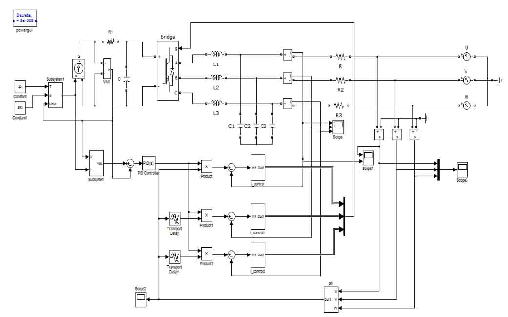
In the process of building the model, we pass the DC power output from the photovoltaic cell through a boost circuit to reach the required DC voltage level for grid connection. Then, it passes through a three-phase full bridge solar inverter, and the inverter output current is integrated into the grid through an LC filter. The grid side voltage is determined by the given voltage. In the process of controlling the system, we sample the output current and grid voltage separately, then obtain the d-axis and q-axis current components through coordinate transformation, compare them with the reference value, and then obtain modulation signals Ud and Uq through PI regulator and repetitive controller. After reverse Park transformation, they are sent to the SVPWM module to generate the required modulation signal to control the three-phase inverter bridge arm, Finally, the grid connected current with the same frequency and phase as the grid voltage is obtained.
A 10KVA three-phase solar grid connected inverter was designed, with a DC side voltage of 700V, a grid voltage of 220V, a switching frequency of 10.5KHz, and a grid frequency of 50Hz. High order harmonics must meet the requirements of IEEE929-2000, and the total harmonic distortion is less than 5%. Through calculation, it can be concluded that the filtering inductance is:
L=2.25 mH, filter capacitance C=10.96 μ F.
The control system of three-phase solar grid connected inverter is shown in Figure 1.
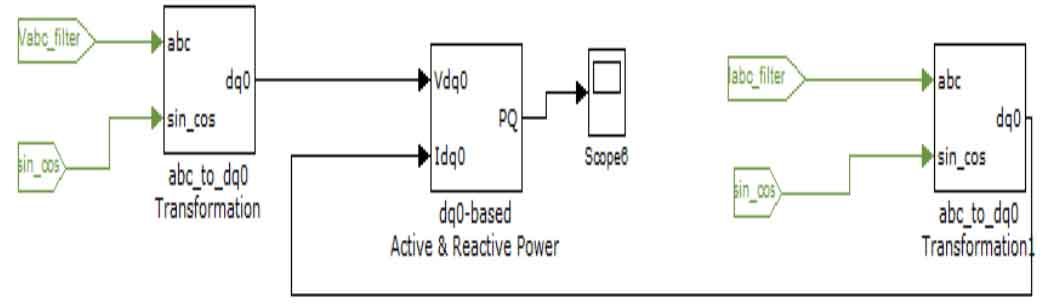
The simulation models for active and reactive power are shown in Figure 2:
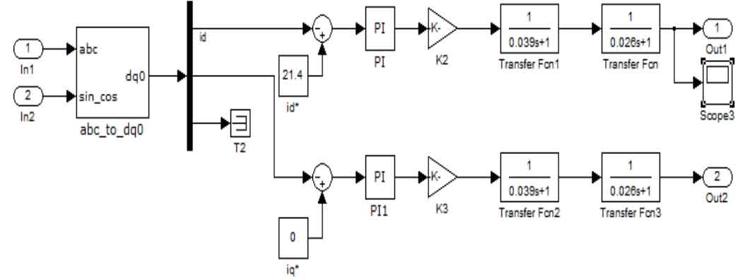
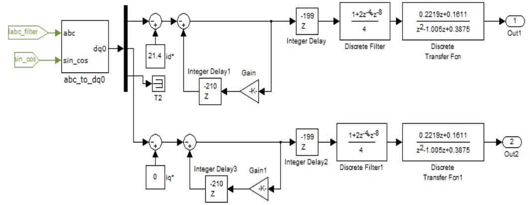
The simulation model of the designed PI regulator is shown in Figure 3:
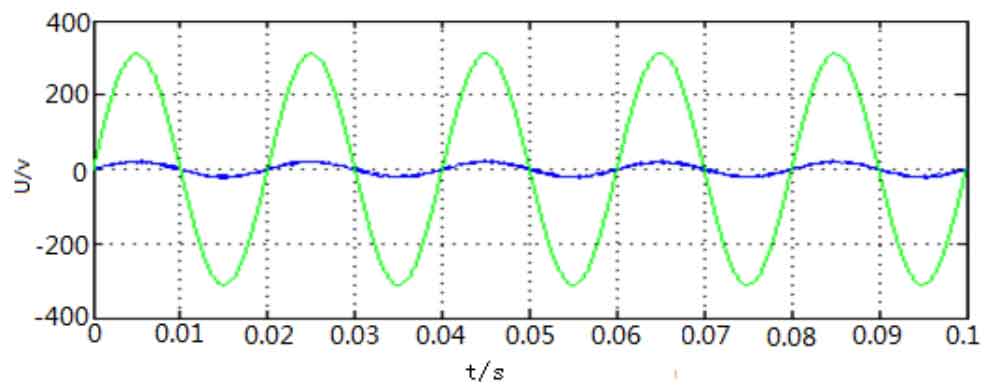
In order to better demonstrate the advantages of combining PI regulation with repetitive control regulation, we first simulated the control system with only PI regulation. The simulation results are shown in Figures 4, 5, 6, and 7:
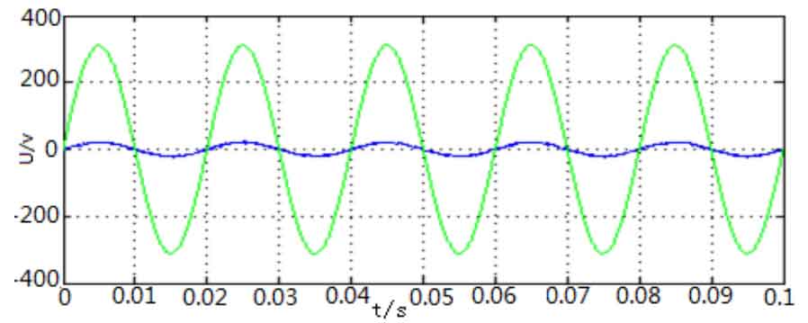

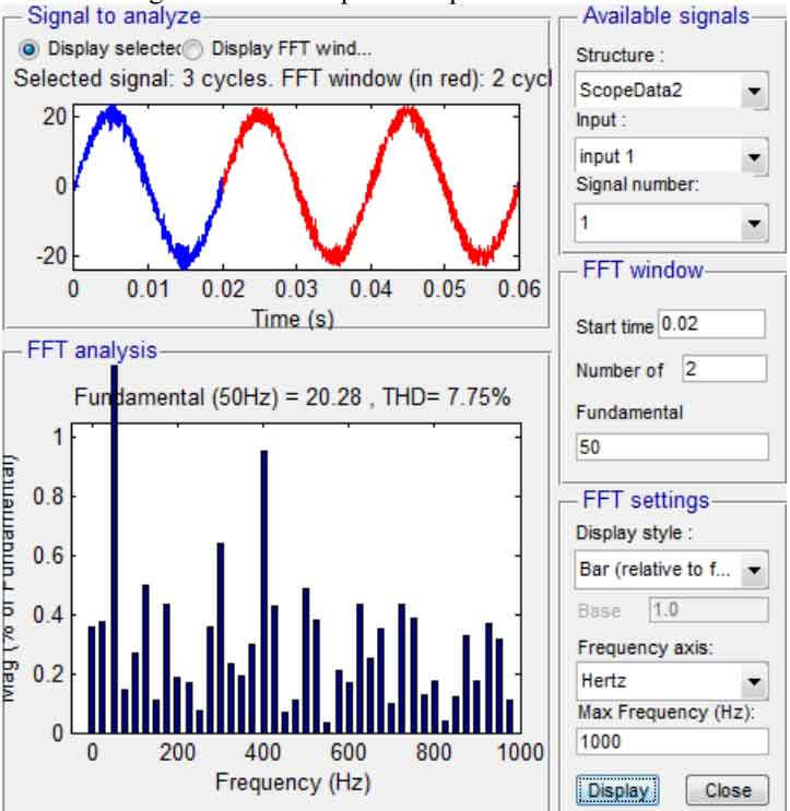
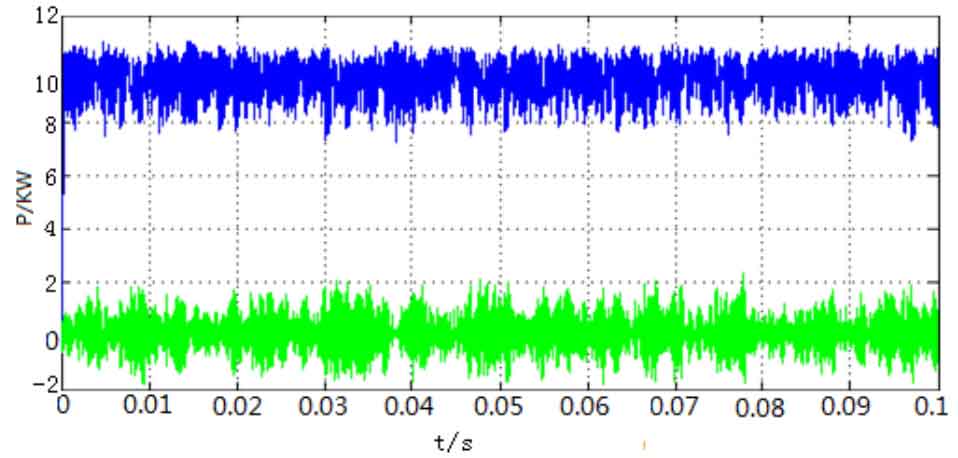
From the above simulation graphics, it can be seen that the overall output current waveform is good, but it contains a lot of harmonic components, THD=7.75%, which cannot meet the requirement of less than 5%. The grid connected current and grid voltage basically achieve the same frequency and phase, with a power factor roughly equal to 1. The active power fluctuates between 8-11KW and the reactive power fluctuates between -2KVar, which cannot effectively suppress periodic disturbances in the power grid, So the effect of only the PI regulator is not very perfect, and it cannot control the output waveform well.
In order to better control the system, we have designed a repetitive controller to be used in parallel with the PI controller to compensate for and correct the output waveform. The simulation model of the repetitive controller is shown in Figure 8:
The simulation after using PI regulator and repetitive controller together is shown in Figures 9, 10, 11, and 12:
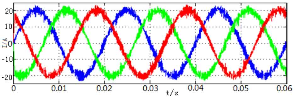
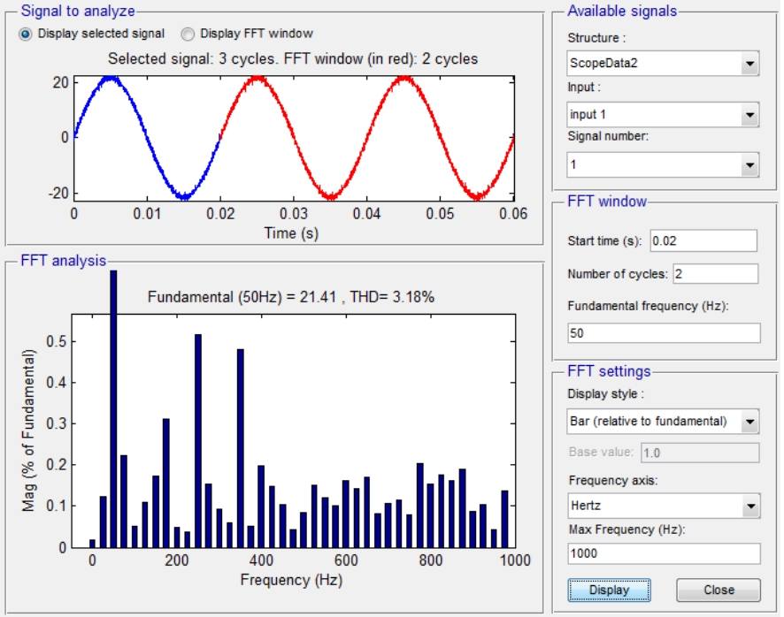
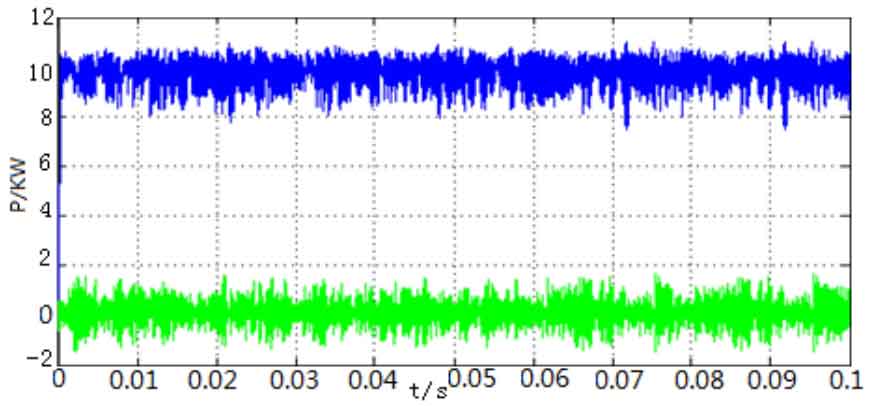
From the simulation, it can be seen that the output waveform has been significantly improved. The grid connected current is in the same frequency and phase as the grid voltage, with fewer harmonics, THD=3.18%, meeting the grid connection requirements. The output power is almost maintained around 10KW, and the reactive power is around 0KVar. This effectively suppresses periodic disturbances in the grid, achieves good control effects, and improves system stability.
We mainly introduced the control strategy of three-phase solar grid connected inverters. Based on the advantages and disadvantages of different control methods, we ultimately adopted a dual closed-loop control of voltage outer loop and current inner loop. The PI controller is easy to operate and has excellent performance, but it cannot effectively suppress the disturbance of periodic signals. Therefore, we propose a repetitive control method. The repetitive control method has strong stability and can effectively suppress harmonic interference caused by periodic disturbances. Finally, we combined the advantages of the two methods and used them together to adjust. We established a simulation model of the entire control system in MATLAB and verified through simulation that the combination of the two methods can effectively improve the quality of the output grid connected current waveform.