
1. Analysis of Microgrid Control for Island Operation
When the photovoltaic microgrid operates in an isolated island state, the energy storage device is the main control micro source of the entire system. By adopting the V/f control method, the photovoltaic power supply and load will adjust the response power and switching based on the instructions issued by the controller. When the grid connected circuit breaker CB is disconnected, the microgrid will switch from grid connected operation to island operation. At this point, the remote controller will receive the opening and closing status of the grid connected circuit breaker CB and issue instructions to the local controllers LC-P1, LC-P2, LC-P3 of the three photovoltaic power generation units, as well as the local controller LC-B of the battery energy storage system; Control the photovoltaic power generation unit to operate in constant power (P-Q) mode, and the battery energy storage system to operate in voltage frequency (V/f) mode to maintain the voltage and frequency of the microgrid.
In the article, the V/f control uses a voltage and current dual closed-loop control method, and the voltage outer loop enables the inverter to stabilize the output voltage and provide certain support for other distributed power sources; The current loop is an inner loop, which can effectively improve the dynamic response speed of the system, while also reducing the harmonic content of the system, thereby comprehensively improving the controllability of distributed micro power sources in the microgrid.
2. SOC control of energy storage batteries in island mode
Due to the fact that the control of the battery energy storage system is mainly based on the SOC constraints of the battery, corresponding measures need to be taken for different operating states of the system. This article adopts the following control strategy, and divides the battery status into two situations based on the range of SOC: within the normal range and outside the normal range. When in island mode and the SOC of the battery is within the normal range, the energy storage system will discharge in case of insufficient power in the microgrid, and enter the charging state when there is excess power in the microgrid. When the SOC of the battery is not within the normal range, discussions need to be conducted based on the actual operation of the system, such as splitting the power generation unit, reducing the load, or conducting battery charging and discharging operations.
Under islanding conditions, the closed-loop process of the battery energy storage system in voltage frequency (V/f) control mode for three photovoltaic power generation units under constant power (P-Q) control mode. For energy storage batteries, they should operate within a controllable range (SOCmin < SOC < SOCmax), which means that battery energy storage can be used for charging/discharging to support the voltage and frequency of island microgrids. The logic is mainly determined by comparing the load situation (PLoad) of the microgrid with the power output of three power generation units (3Ppv), which can be divided into the following two situations:
(1) If the power output of three power generation units is less than the system load (i.e. 3PPV ˂ PLoad), the energy storage battery is discharged, and the compensation microgrid power is insufficient to restore the microgrid frequency.
(2) If the power output of three power generation units is greater than the system load (i.e. 3PPV>PLoad), the energy storage battery is charged, consuming excess power in the microgrid to stabilize the microgrid frequency.
When the SOC of the battery is not within the normal range, it is determined by the SOC of the battery, the load condition of the microgrid (PLoad), and the power of the three power generation units (3Ppv), which are mainly divided into the following four situations:
(1) If the power output of three power generation units is less than the system load and SOC ≤ SOCmin, low-frequency load shedding operation is performed on the microgrid load to stabilize the system frequency.
(2) If the power output of three power generation units is less than the system load and SOC>SOCmax, the battery will start discharging to compensate for the lack of active power in the system.
(3) If the power output of the three power generation units is greater than the system load and SOC ≤ SOCmin, the battery begins to charge to absorb excess active power in the system.
(4) If the power output of three power generation units is greater than the system load and the SOC is greater than SOCmax, the photovoltaic power generation unit will be split to limit its active output.
3. V/f control of inverters
The grid connection/island mode switch studied adopts manual mode, which is achieved by manually setting the number of grid connected circuit breakers CB (grid connection mode is 1, island operation mode is 0). The remote controller will receive the current state change and issue instructions to the four local controllers LC.
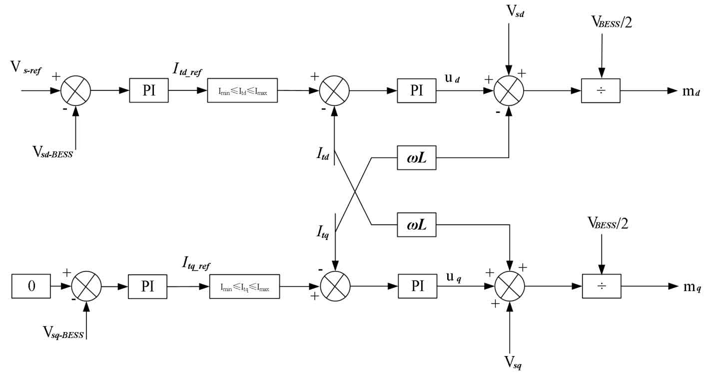
In island mode, the battery energy storage system serves as the main control unit, and the voltage of the microgrid is adjusted by the battery energy storage system based on voltage feedback from its inverter. When operating in an isolated island, the VSC control in the battery energy storage system switches from P-Q control mode to V/f control mode.
The voltage source inverter control block diagram of the battery energy storage system is shown in Figure 1. The voltage and current dual closed-loop control adopted mainly relies on the dq rotating coordinate system, which directly transforms the three-phase AC signal into a DC signal in the dq rotating coordinate system, thus achieving separate control. In the control of constant voltage and frequency, Usqref is directly set as the reference voltage. In this article, Vs_ Ref is set to the rated value of 1 pu, Vsq is set to 0, and the battery energy storage system has an internal oscillator to generate and apply the frequency of the microgrid in island mode, that is, the frequency is set to power frequency 50Hz( ω= 2 π fref). In the current inner loop, by adding decoupling links, the dynamic response speed of the system can be greatly improved, as follows:
The output voltage dq axis components (Utd, Utq) can be obtained. The modulation components md and mq obtained are transformed by dq/abc and then input into the SPWM pulse generator to obtain the IGBT driving signal, thereby controlling the AC output of the inverter.
4. Simulation analysis of microgrid islanding operation
In order to study the correctness and stability of the microgrid control strategy in island mode in this article, simulation was conducted on the Matlab/Simulink software platform. The operation of microgrid systems transitioning from grid connected mode to island mode, power reduction or load reduction, and microgrid reconnection to the main grid were discussed, analyzed, and verified.
4.1 Simulation analysis of grid connection transition to island mode
In order to clearly compare and analyze the changes between the two states, manually change the grid connected circuit breaker state at t=5s, that is, the entire microgrid will transition from grid connected state to island state operation. The instantaneous state of the transition of microgrids from grid connected mode to island mode can be analyzed and discussed through the following figure.
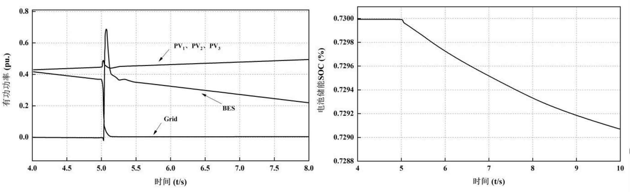
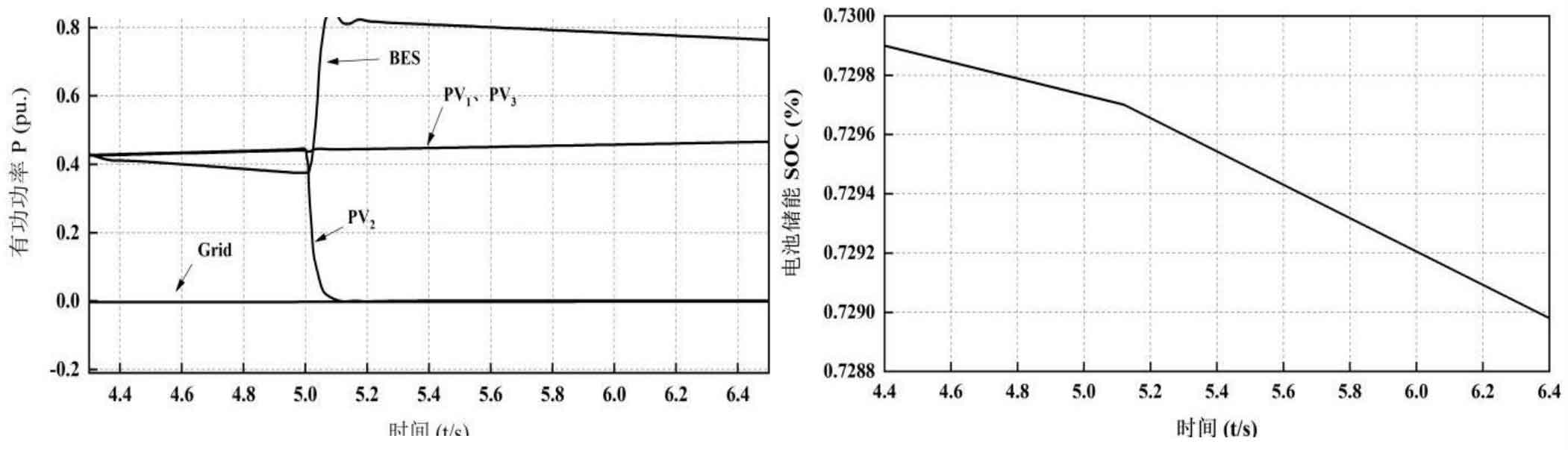
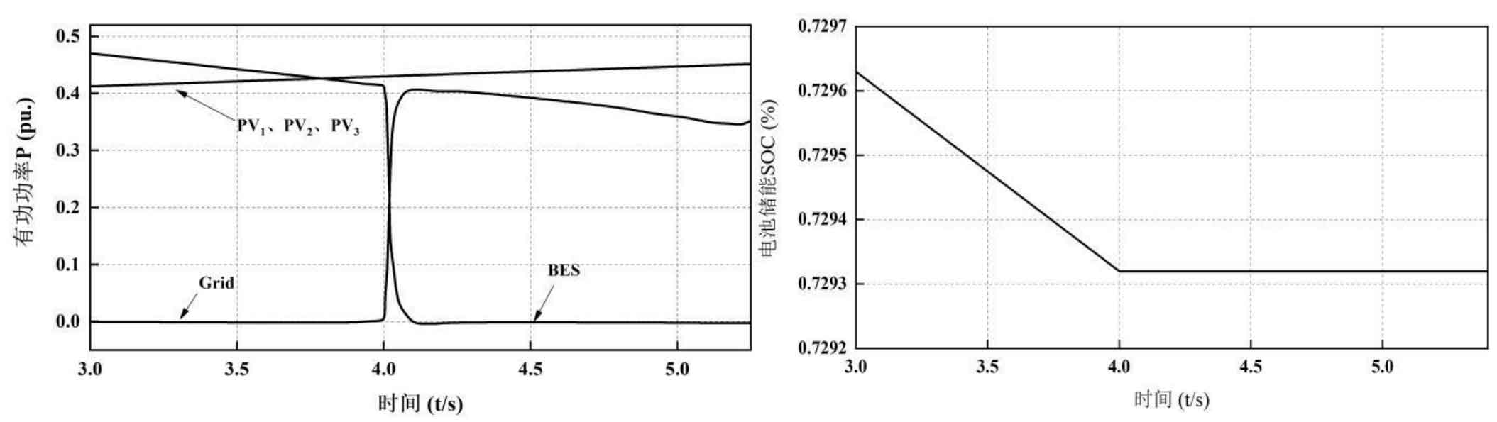
Figure 2 shows the changes in active power of the main grid and battery energy storage for photovoltaic power generation units in grid connected/island connected modes. Before the island mode (t ≤ 5s), the active power transmitted by the main grid to the microgrid was 0.41 pu, while the active power transmitted by the three photovoltaic power generation units was 0.43 pu. The battery energy storage remained idle under the grid connection mode control strategy without power exchange. After island mode (t>5s), the battery energy storage begins to discharge at rated power to quickly control the voltage and frequency of the microgrid, and enters V/f control mode for operation. And the three photovoltaic power generation units continue to track the reference power according to their MPPT control strategy, maintaining P-Q mode operation. It can be seen that their power maintains an increasing trend with changes in time and irradiation curve.
Figure 3 shows that the battery energy storage in grid connected mode is a constant straight line at t ≤ 5s, with a value of 0.7 within the normal range of SOC. After t>5s, the battery energy storage system begins to discharge at rated power, and it can be observed that the SOC value decreases in a smooth curve, reaching 0.7291 at t=10s.
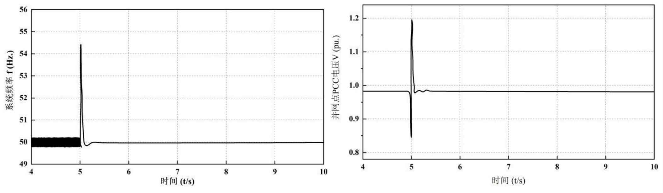
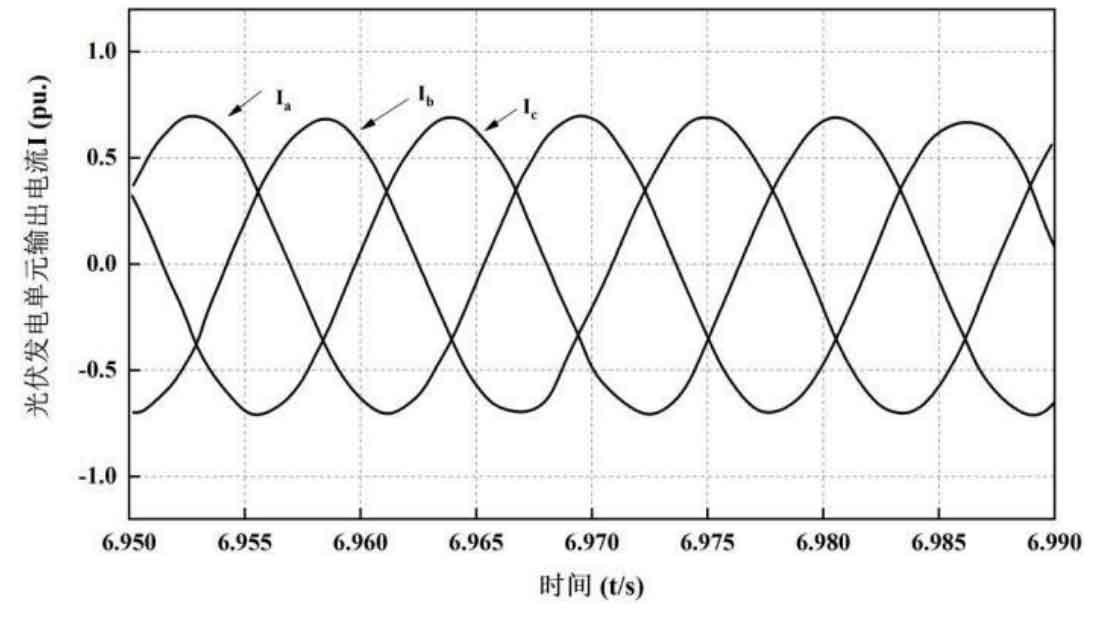
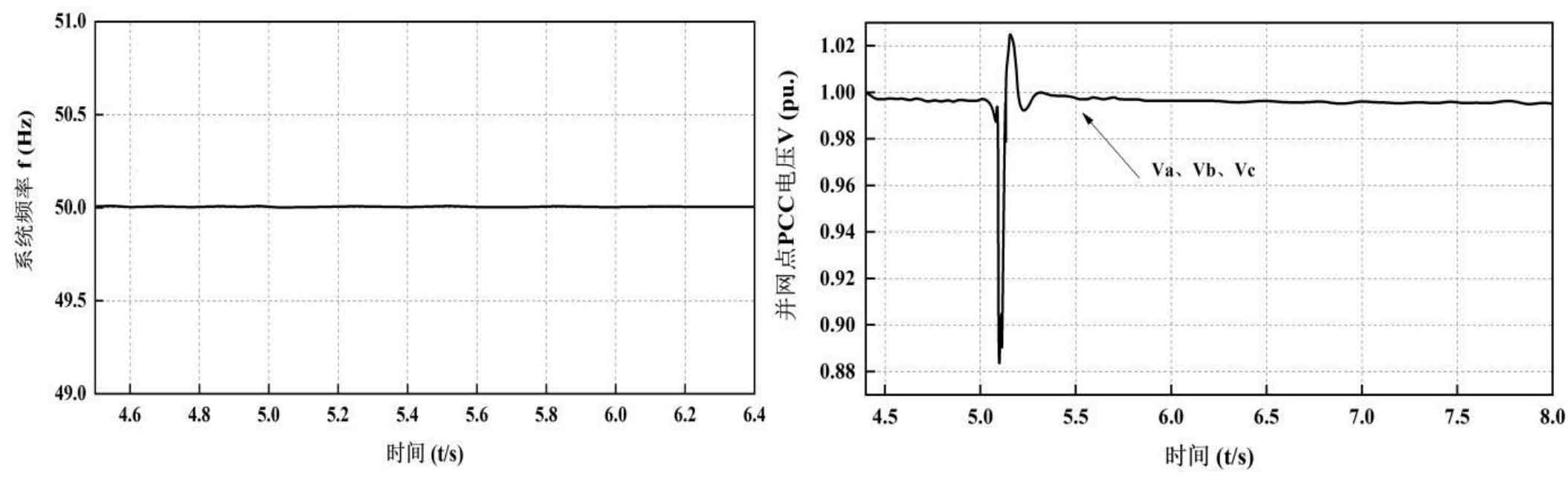
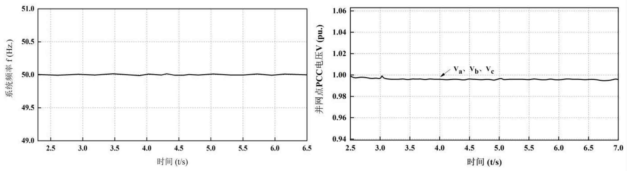
Figures 4 and 5 show the changes in the frequency and voltage of the microgrid during the transition period. The instantaneous frequency and voltage from grid connected state to island state undergo a jump, and after 0.1 seconds, the frequency returns to 50Hz, and the voltage at the grid connected point (PCC) also returns to its rated value, maintaining stability. Figure 6 shows the steady-state instantaneous output current of each photovoltaic power generation unit and battery energy storage during the process, with current values within the rated range and three-phase output current balanced.
4.2 Simulation analysis of power generation unit splitting
At the beginning, the system was in a stable and isolated operating state, with a constant load. At the initial time t=4.2s, the output power provided by the three photovoltaic power generation units and battery energy storage to the microgrid is 0.42 pu. At t<5s, the power of the three photovoltaic power generation units maintains an increasing trend as time and irradiation curves change, while the output power of battery energy storage gradually decreases due to constant load. Manually set the photovoltaic power generation unit PV2 at t=5s, and after 0.1s, the output power becomes 0 pu to simulate a photovoltaic power generation splitting situation. The following figure can be used to analyze and discuss the transient response of the system when a photovoltaic power generation unit experiences losses in island mode.
As shown in Figure 7, when the system is in island mode, the power output from the main grid to the microgrid is 0. At t=5.1, the photovoltaic power generation unit PV2 is disconnected, and its output power drops to 0. The output power of the battery energy storage system rapidly increases within 0.1 seconds to support the active power consumption of the microgrid. Subsequently, at t>5.2 seconds, the increase in irradiation intensity led to an increase in the output active power of photovoltaic power generation unit PV1 and photovoltaic power generation unit PV3, and the output power of the battery energy storage system showed a downward trend. Figure 8 shows the change in SOC of the battery in the island mode when the energy storage is in the discharge state. As the output of photovoltaic power generation units increases, the reduction rate of SOC shows a downward trend. When the photovoltaic power generation unit PV2 is disconnected at t=5.1 seconds, the rate of SOC value decrease significantly increases to quickly supplement the power gap in the microgrid.
From Figures 9 and 10, it can be seen that in island mode, the frequency and voltage changes of the microgrid after one photovoltaic power generation unit is disconnected. The frequency of the microgrid is always maintained at 50Hz, and the voltage of the grid connection point (PCC) also drops instantly when the power generation unit is disconnected. With the introduction of the battery energy storage system, it rapidly increases, and then remains stable, resulting in stable system operation.
4.3 Simulation analysis of load shedding
At the beginning, the system is in a stable and isolated operating state, with a constant load. At the initial time t=2s, the output power provided by the three photovoltaic power generation units to the microgrid is 0.4 pu, and the output power provided by the battery energy storage to the microgrid is 0.52 pu. Disconnect load 1 of the network at t=3 seconds to simulate a system load shedding situation.
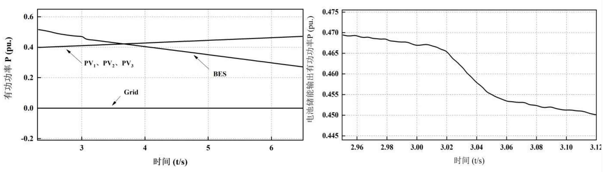
From Figures 11 and 12, it can be observed that the output power provided by the battery energy storage to the microgrid is 0.466 pu at t=3.12 seconds, until its output power becomes 0.45 pu at t=3.12 seconds. When the load decreases, there is a significant decrease in the output of battery energy storage, which is caused by the battery energy storage system adjusting the power balance of the microgrid in V/f control mode under load reduction conditions.
Figures 13 and 14 show the changes in frequency and voltage of the microgrid after load shedding in island mode. During this process, the frequency of the microgrid remains at 50Hz and the voltage remains stable.
4.4 Simulation analysis of reconnecting to the main network
In order to clearly compare and analyze the changes in the two states, manually change the state of the grid connected circuit breaker from open to closed at t=4s, meaning that the entire microgrid will transition from an isolated state to a grid connected state for operation. The transient response of the microgrid transition system from island mode to grid connected mode can be analyzed and discussed through the following figure.
From Figure 15, it can be seen that at the time t<4s, the microgrid operates in island mode, with each photovoltaic power generation unit outputting 0.43 pu of active power to the microgrid, while the battery energy storage system provides 0.41 pu of output active power to the microgrid. At t=4s, the microgrid switches from isolated island to grid connected mode. At this moment, the battery energy storage system switches to P-Q mode operation, maintaining an idle state with an output power of 0.
Figure 16 shows the change in SOC of the microgrid from islanding to grid connection mode. Before the time t=4s, the battery is in a discharge state to maintain the balance of power in the island microgrid. The SOC value changes from 0.72963 to 0.72932, until the time t ≥ 4s, the battery energy storage is in an idle state, and its SOC value no longer changes.
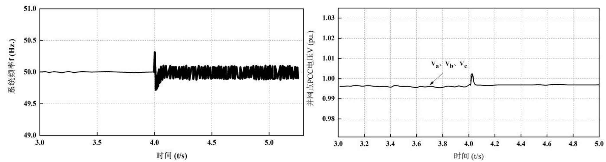
Figures 17 and 18 show the changes in frequency and voltage of the microgrid during the transition period. From the isolated state to the grid connected state, an oscillation occurred instantaneously, and after 0.1 seconds, it returned to normal. The frequency remained at 50Hz, and the voltage remained near the rated voltage. After switching to grid connected mode, the microgrid could also operate smoothly.
5. Summary
This article explains the control strategy adopted in the island mode, and analyzes and discusses the master-slave control mode and V/f control mode. The method of combining V/f control and P-Q control is adopted. In island mode, the photovoltaic power generation unit is in P-Q control mode, and the battery energy storage system is in V/f control mode. Simulation verification was conducted under variable irradiation intensity. We analyzed the operation of the system under four different conditions: the transition from microgrid connection to islanding, power generation unit disconnection, load shedding, and reconnection from the islanding to the main grid. We focused on observing the changes in active power, voltage, frequency, and current of the system. During this process, the battery energy storage system was able to maintain the voltage of the microgrid at its rated value and maintain its frequency at 50 Hz in island operation mode, meeting the requirements of V/f control and verifying the correctness of the strategy. Meanwhile, based on the transition state of grid connection/islanding, this strategy can achieve a smooth transition between the two states.
With the widespread application of microgrid technology in recent years, as the future backbone power grid continues to improve and strengthen, microgrids based on distributed clean energy generation or comprehensive energy optimization utilization will have good development prospects. Compared to traditional large-scale centralized transmission and distribution models, microgrids have emerged as a more flexible, intelligent, and reliable system. Microgrid is a power system that integrates centralized control centers, distributed power sources, user loads, and energy storage devices. It can be connected to the grid at any time or disconnected from the grid to achieve isolated operation. This article investigates the operation and control of photovoltaic microgrids and battery energy storage systems, which consist of three photovoltaic power generation units and one energy storage system composed of lithium batteries.
A simulation model for photovoltaic power generation units and energy storage systems was established by studying the mathematical models and characteristics of photovoltaic and lithium batteries. At the same time, to address the issue of maximum power point tracking (MPPT) in photovoltaic power generation, an adaptive variable step disturbance observation method was proposed by improving the traditional variable step disturbance observation method. The feasibility of this method was verified through simulation software. By carrying out the above work, a foundation is laid for the research of microgrid control strategies in the following text.
Based on the constant power control mode, the control strategies of photovoltaic power generation units and battery energy storage systems in grid connected state were studied. The photovoltaic power generation unit was mainly implemented using MPPT, while the battery energy storage system was based on its SOC implementation. A logic control scheme for SOC was proposed, and a small margin comparison link was added within the original range based on its constraint conditions to prevent the battery from repeatedly charging and discharging at its upper and lower critical points, In order to reduce battery loss and improve its work efficiency. Furthermore, a remote controller (SC) was constructed to enable the control modes of the microgrid to switch between grid connected and isolated islands, as well as four local controllers (LCs) to execute commands issued by the SC, selecting the control modes of three sets of photovoltaic power generation units and battery energy storage systems. In addition, the focus is on analyzing the control process of photovoltaic power generation units and energy storage systems under grid connection conditions, and proposing a current inner loop closed-loop feedback control strategy in grid connection mode to achieve constant power control of photovoltaic power generation units and energy storage systems. Finally, simulation was conducted on the control operation of the microgrid under variable irradiation intensity and different initial states of the energy storage system. The results verified the effectiveness of the model and the correctness of the control strategy.
A logic control scheme for SOC in island mode is proposed based on constant voltage and frequency control in master-slave control mode. The battery energy storage system serves as the main control unit to support the voltage and frequency of the microgrid. Furthermore, a voltage outer loop and current inner loop closed-loop feedback control strategy was proposed for the battery energy storage system in island mode. Simulation was conducted on the operation of the microgrid under several conditions such as transition from grid connection to island, generation unit disconnection, load shedding, and reconnection from the island to the main grid. The simulation results showed that under this control strategy, the microgrid can operate stably in island mode, And it can achieve smooth conversion in two modes: grid connected operation and island operation.