
1. Master slave control of microgrids
According to the different situations of each distributed power source, the master-slave control method adopts different control strategies to achieve different functions. In microgrids, distributed power sources are used as the main control unit to measure various electrical quantities on the network side and make different adjustments based on the operating status of the grid. Other slave control units are connected to the main control unit through communication lines for output.
Master slave control is widely used for parallel/off grid operation of microgrids. After connecting the microgrid to the power grid, all micro power sources in the system are controlled by constant power, and the voltage and frequency are determined by the power grid. For stable units (such as batteries), the power output is determined based on the set power, while for unstable units (such as photovoltaic inverters), the output is based on their maximum power tracking point. At this point, microgrids can output energy to and absorb energy from the large grid. When the microgrid is disconnected from the grid side and operates without the grid, it needs to have a stable voltage and frequency. At this point, one or more units are required to assume the responsibility of stabilizing the voltage and frequency of the power grid, which is the main control unit of the system.
In master-slave control, the master control unit uses constant voltage and frequency to control the output of stable voltage and frequency, while other slave control units still use constant power to control their output power to maintain power balance between the system and local loads.
From this, it can be seen that the main control unit is a very important part of master-slave control. It requires a very large capacity, and the output can be adjusted within a certain range, and can respond quickly to changes in load.
1.1 Constant power control
For the common intermittent distribution of new energy sources in microgrids, such as solar and wind energy, their output power is easily affected by external factors, and P-Q control (i.e. constant power control) is usually used to improve the stability and energy utilization efficiency of the grid.
The fundamental of this control method is to achieve stable voltage and frequency for distributed power sources, and output active and reactive power based on their initial set values. In the entire power grid, tasks unrelated to its own output are not involved, such as power imbalance caused by load changes, power quality degradation, etc. These are usually regulated by large power grids or micro power sources using other control methods.
1.2 Constant voltage and frequency control
The purpose of V/f control is to always maintain the voltage and frequency of distributed power sources at a constant level. When the microgrid is in an isolated operation state, due to its characteristics of constant voltage and constant frequency control, the micropower supply using this control mode is usually used as the main control unit of the microgrid in the master-slave control mode, and supports the voltage and frequency of the entire microgrid, so that other subordinate control units can work normally.
The constant voltage and frequency control unit is the core part of master-slave control. It is mainly used to maintain the voltage and frequency stability of the microgrid. In order to ensure the normal operation of the entire system, the main control unit needs to balance the gaps in the system. In order to prevent microgrid failures, the micropower supply using this control method must have a large capacity.
2. The control strategy adopted in this article
The control strategy of this article is based on the collaboration between a remote controller (SC) and four local controllers (LC-B, LC-P1, LC-P2, LC-P3). The remote controller (SC) detects the status of the grid connected circuit breaker CB and sends commands to four local controllers. The energy storage system local controller LC-B discussed in this article has two types of control (P-Q and V/f control), and the photovoltaic power generation unit has one control mode (P-Q control). Therefore, the switching between grid connected/island mode only needs to be studied for LC-B. In the text, LC-B selects the corresponding control mode based on the state of the SC. When the remote controller’s SC state variable is 1, the local controller’s LC-B state variable is also 1, which means grid connected operation; When the remote controller SC state variable is 0, the local controller LC-B state variable is 0, which means island operation. Since LC-P1, LC-P2, and LC-P3 are always in P-Q control mode, their state variables are always 1. The conversion of two control modes is achieved through the logical correspondence between the state variables of the controller mentioned above.
In grid connected mode, both the photovoltaic power generation unit and the battery energy storage system adopt constant power (P-Q) control. The photovoltaic power generation unit provides reference active power Pref for the local controller (LC) through maximum power point tracking (MPPT). From the structure of the battery energy storage system, it can be seen that the reference active power PBref of the local controller of the battery energy storage system is determined by its SOC. In grid connected mode, the microgrid can receive stable voltage and frequency through P-Q control, while the power generation unit and energy storage system output active and reactive power according to their own settings. The demand for reactive power in the network in this article is not considered, that is, the reference reactive power of all photovoltaic power generation units and battery energy storage is set to 0.
In island mode, when the grid connected circuit breaker CB is disconnected, the LC-B control mode of the battery energy storage system will switch from constant power (P-Q) control mode to voltage/frequency (V/f) control mode to support the voltage and frequency of the entire microgrid. The photovoltaic power generation unit is still controlled by constant power (i.e. P-Q).
In grid connected mode, the voltage and frequency of the microgrid are determined by the main grid. Active and reactive power can be effectively exchanged between the microgrid and the main grid.
The control strategy of photovoltaic power generation units in grid connected mode (P-Q control) is achieved by tracking the maximum power point (MPPT) and exchanging active and reactive power with the main grid through the current controller of its inverter. The control strategy of a battery energy storage system should take into account the relationship between battery SOC and, similar to photovoltaic power generation units, regulate active and reactive power through the current controller of its inverter.
The control strategy for photovoltaic battery energy storage in grid connected mode has two characteristics:
(1) Track and control the maximum output power of photovoltaic power generation units through an effective MPPT method.
(2) Control the battery SOC at a certain level to ensure the voltage and frequency of the microgrid in island mode. In grid connected mode, maintain it within a normal range based on the actual situation of SOC to avoid repeated charging and discharging, and ensure the safety and stability of the energy storage system.
The closed-loop process of three photovoltaic power generation units and battery energy storage systems under constant power (P-Q) control mode under grid connection conditions. For energy storage batteries, they should operate within the range of SOCmin ≤ SOC ≤ SOCmax.
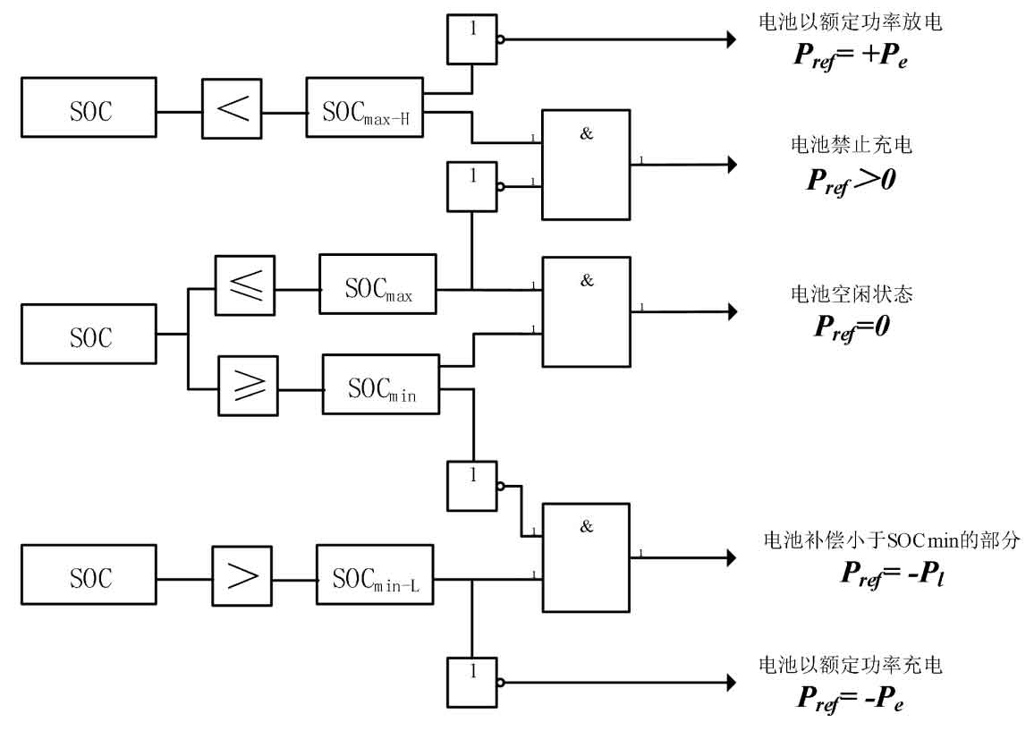
Add SOCmin-L and SOCmax-H comparison links in the control loop to save energy and prevent the battery from repeatedly charging and discharging at its upper and lower critical points, thereby reducing the loss of energy storage batteries and improving their work efficiency. The charging and discharging logic based on energy storage battery SOC is as follows:
If the SOC of the energy storage battery is within its normal range (SOCmin ≤ SOC ≤ SOCmax), the local controller LC-B sets the reference active power of the battery to zero (PBref=0). Due to not considering reactive power output (QBref=0), the energy storage system remains idle in the P-Q control mode under grid connection conditions.
If the SOC of the energy storage battery is ≤ SOCmin-L, the local controller LC-B charges the battery at its rated power until it reaches the normal range.
If the SOC of the energy storage battery is ≥ SOCmax-H, the local controller LC-B will discharge the battery at its rated power until it reaches the normal range.
If the energy storage battery SOCmin-L<SOC<SOCmin, the local controller LC-B compensates for the portion of the battery charge that is less than SOCmin to prevent repeated charging and discharging of the battery near SOCmin and reduce battery loss. If the energy storage battery SOCmax<SOC<SOCmax-H, the local controller LC-B will prohibit the battery from charging.
3. Control of photovoltaic power generation units in grid connection mode
The control structure of a single photovoltaic power generation unit includes MPPT control, DC voltage control, and voltage source inverter control. The control logic is to provide the reference DC voltage (VDC_ref) to the DC voltage controller through MPPT control. The DC voltage controller generates reference active power (PSref) for the voltage source inverter system.
The current controller of the voltage source inverter system controls the output power of the voltage source inverter system by providing modulation indicators of the SPWM scheme of the voltage source inverter system to track the AC power reference generated from the DC voltage controller. Regardless of the demand for reactive power in the network, there is a remote controller (SC) that sets the reference reactive power (QSref) of the photovoltaic power generation unit to 0.
3.1 Control of Maximum Power Point Tracking (MPPT)
According to the characteristics of photovoltaic cells, each photovoltaic power generation unit adopts an improved adaptive variable step disturbance observation method MPPT algorithm. The MPPT control strategy mainly receives the terminal voltage (VDC) and current (IDC) of the photovoltaic power generation unit and transmits them to the DC voltage controller as a reference voltage VDC_ Ref.
The MPPT algorithm first searches for voltage V (k) and current I (k) through continuous disturbances to obtain their corresponding active power P (k). Then, by comparing the difference between P (k) and P (k+1) before and after, and introducing parameter e, it is calculated whether to enter the step size adjustment stage (parameter adjustment stage). Then, the positive and negative relationship between the difference between the two △ P values and the voltage size is determined, To determine the direction of the next disturbance, in order to obtain the optimal VDC and IDC in the MPPT control link.
3.2 Control of DC voltage controller
The DC output power of the photovoltaic power generation unit passes through the DC capacitor C1, and its voltage is related to the AC output power of the inverter. There is the following formula:
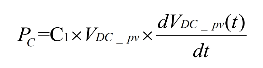
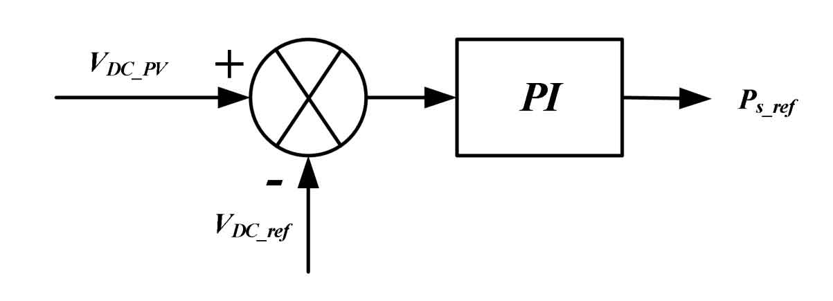
The main function of DC capacitors is to adjust the deviation between the DC input and AC output terminals in the balance system. When the DC input is greater than the AC output, the voltage at both ends of capacitor C1 will increase; When the DC input is smaller than the AC output, the voltage at both ends of capacitor C1 will decrease; When the DC input and AC output are equal, the voltage at both ends of capacitor C1 remains constant. As shown in Figure 1, MPPT generates a DC reference voltage VDC_ Ref and terminal voltage VDC of photovoltaic power generation unit_ Compare PV and generate AC reference active power PS for the inverter control system through the regulation of the proportional integral (PI) controller_ Ref.
According to the formula, determine the parameters that need to be adjusted for the PI controller:
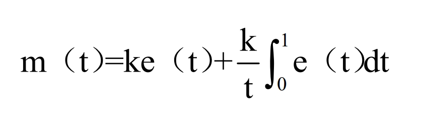
In the formula, m (t) is the output quantity, e (t) is the input quantity, k is the adjustable proportional coefficient, t is the adjustable integral time constant, and k=3 and t=0.1 are taken in the text
3.3 P-Q control of inverters
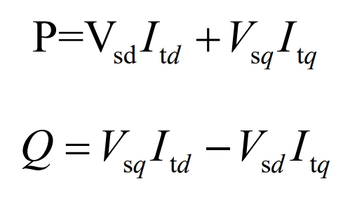
Based on the mathematical model of a three-phase bridge voltage source inverter, in the three-phase stationary coordinate system, the output power of the three-phase inverter is:
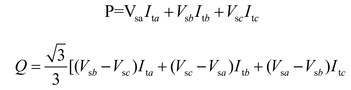
Transforming it into a two-phase transformation coordinate system yields:
The transformation of three-phase voltage from a three-phase stationary coordinate system to a two-phase rotating coordinate system:
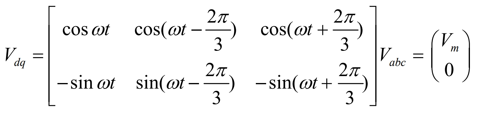
It can be seen from the formula that in the three-phase stationary coordinate system, the three-phase voltage is coupled, and through decoupling, Vd and Vq can be independent of each other in the two-phase rotating coordinate system. When the power system operates normally with three-phase symmetry and no zero sequence components generated, there is Vd=Vm, Vq=0, and the formula can be applied to obtain:
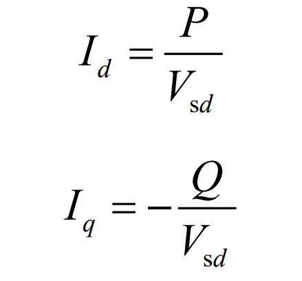
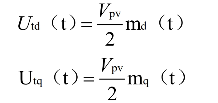
The inverter terminal voltage is obtained by changing the formula, and is represented by the formula:
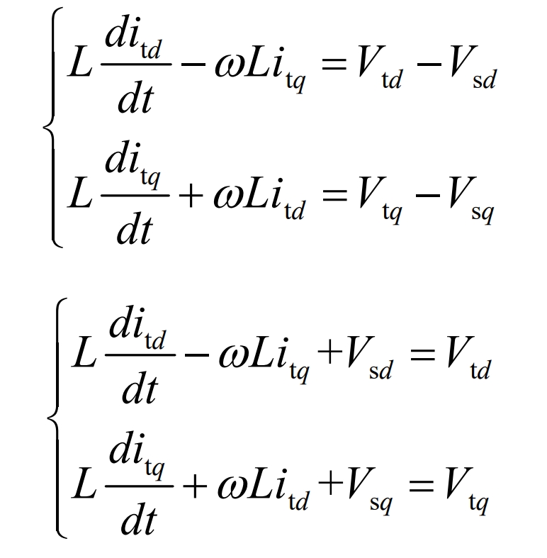
From the above equation, it can be seen that by transitioning from a three-phase stationary coordinate system to a two-phase rotating coordinate system, as long as Id and Iq are controlled, the output power of the inverter can be controlled to achieve constant power (P-Q) control.
The control block diagram of the voltage source inverter is shown in Figure 2. The AC power controller receives reference active power and reactive power (PS ref, QS ref) from the DC voltage controller and the remote controller SC, respectively. In the control process of the inverter, there are two parts: a power regulator and a current regulator. Adjust the range of power through a power regulator (in this article, 0 ≤ P ≤ 1).
Without considering the demand for reactive power in the network (i.e. Q=0), the current regulation range of Itd and Itq in the current regulator is determined by the rated power of the inverter.
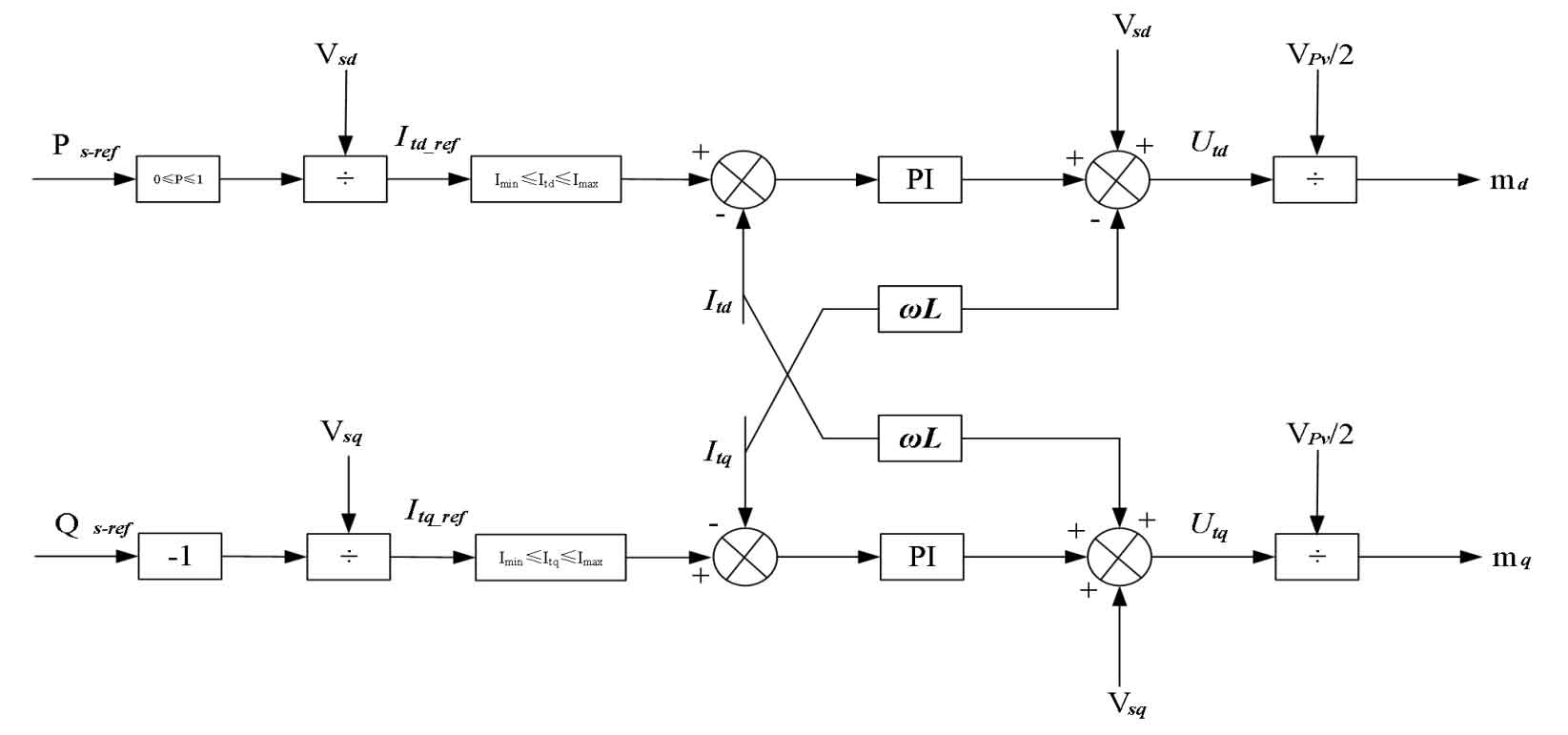
Through the previous section, the reference currents Itd ref and Itq ref can be obtained. After comparing them with the actual currents Itd and Itq, they are sent to the PI controller. The output is then combined with various coupling voltage terms to form an output. The output voltage dq axis components (Vtd, Vtq) are obtained through the formula, and finally input into the SPWM pulse generator to obtain the driving signal of the IGBT. The current PI controller parameters are k=0.1 and t=0.2.
The formula provides a calculation method for modulation indicators md and mq for voltage source inverters, including:
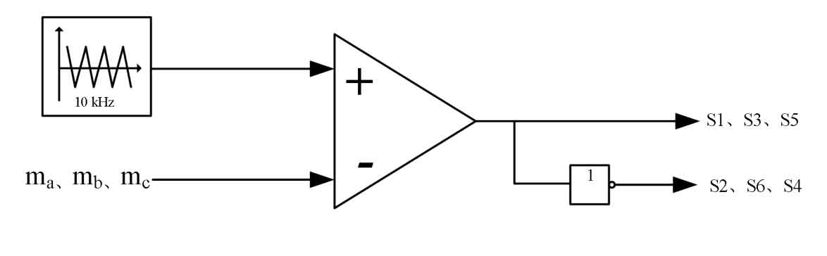
Then, md and mq are transformed by dq/abc to form modulation indicators ma, mb, and mc, which are compared with a 10kHz triangular waveform carrier. The intersection point of the carrier signal and the modulation signal determines the opening time of the IGBT switch S1-S6 of the inverter to achieve sinusoidal pulse width modulation (SPWM). As shown in Figure 3, a phase-locked loop (PLL) is added during the control process to ensure that the phases of Ut, Us, It, and Is are always consistent.
4. Control of battery energy storage system in grid connection mode
Figure 4 shows the control structure of the battery energy storage system, including battery constrained logic control and voltage source inverter control. The control process is battery constrained logic control, which generates reference active power (PSref) for the inverter system, and the remote controller SC generates reference reactive power (QSref) for the inverter system. This article does not consider the demand for reactive power in the network, that is, there is a remote controller (SC) that sets the reference reactive power (QSref) of the battery energy storage system to 0.
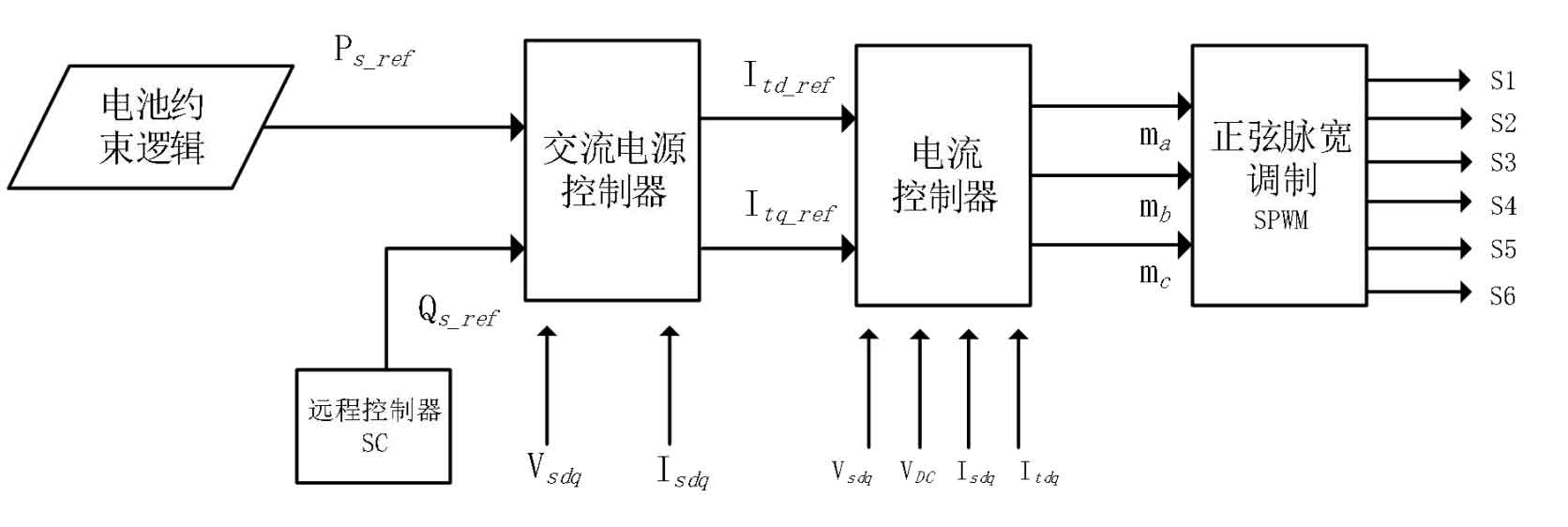
According to the constraint logic of battery energy storage, the battery energy storage system is in constant power (P-Q) control mode under grid connection conditions. Given the following values in Figure 5: 70%=SOCmin ≤ SOC ≤ SOCmax=75%, the battery remains in a normal idle state. To reduce battery loss and prevent repeated charging and discharging between the critical point of 70% and 75%, SOCmin-L=69%, SOCmax-H=76%, and set the upper limit of battery charging to 90% of its capacity and the lower limit of discharge to 30% of its capacity.
In island operation mode, the maximum discharge capacity of the battery storage system is 45% of its capacity (75% discharge to 30%), and the maximum charging capacity is 20% of its capacity (70% charge to 90%).
According to the working characteristics of the battery energy storage system, the corresponding reference power (PSref) can be obtained by tracking the SOC state of the battery in the local controller LC and transmitted to the inverter system.
5. Simulation analysis of microgrid connected operation
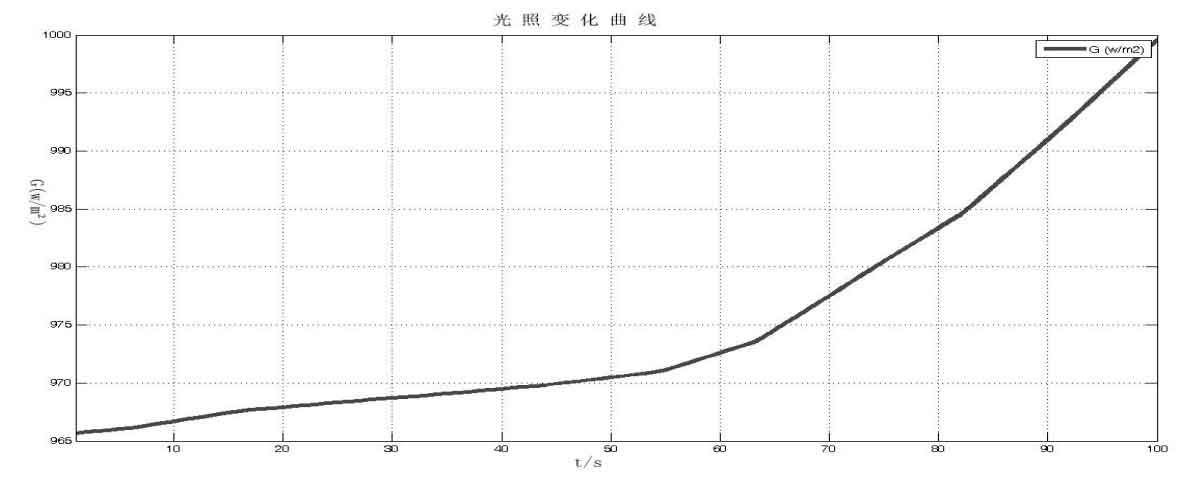
In order to study the correctness and stability of the microgrid control strategy in grid connection mode in this article, simulation was conducted on the Matlab/Simulink software platform. Three situations were analyzed and verified: the battery energy storage system is in an idle state, the battery energy storage system is in a charging state, and the battery energy storage system is in a discharging state under variable light intensity. The variation of light intensity in a certain area is shown in Figure 6. From the graph, it is observed that the radiation variation from 0 to 40 seconds is approximately linear. The relationship between light intensity and time is as follows:
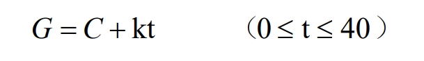
In the formula, C is the illumination intensity at time 0, and k is taken as 0.1 as the input for three photovoltaic power generation units. According to the corresponding requirements for power supply reliability, the power quality of the microgrid in the text should meet the conditions of voltage change rate ≤ 10% and frequency change ≤ 1Hz.
5.1 Simulation Analysis of Battery Energy Storage System in Idle State
Figure 7 shows the variation of active power in the system under variable lighting conditions (expressed as per unit value). Three photovoltaic power generation units have the same power curve with changes in lighting. At the initial moment, three photovoltaic power generation units deliver 0.4pu of active power to the microgrid, while the main grid delivers 0.51 pu of active power to the microgrid. The battery energy storage SOC is set to 0.73 to maintain a constant and idle state, and the BESS outputs 0 active power (the output current is also 0). As the light intensity increases, the MPPT tracks and controls the active output of the photovoltaic power generation units. At t=13s, the output active power of the three photovoltaic power generation units is 0.55pu, and at this time, the main grid no longer transmits active power to the microgrid. Afterwards, the remaining electricity from the microgrid will be output to the main grid.
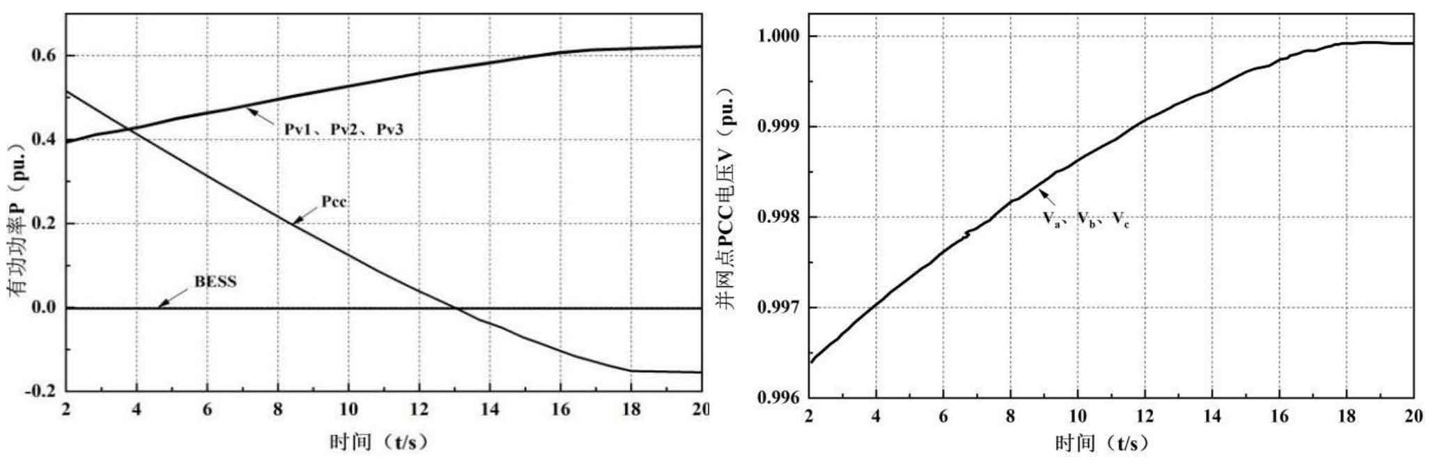
Figure 8 shows the changes in voltage at the point of connection (PCC). As the output power from the main grid to the microgrid decreases at t=2s, the voltage value also returns to the rated value after t=13s, and the rate of voltage change remains within the normal range throughout this process.
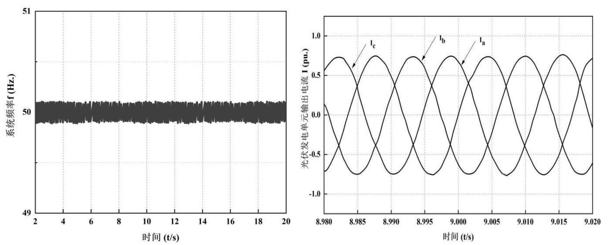
Figure 8 shows that the system frequency stabilizes at 50.0 Hz during this process. Figure 9 shows the instantaneous output current of three photovoltaic power generation units at t=9s in grid connected operation mode. In the constant power (P-Q) control mode, the output current of the power generation unit remains balanced at all times.
5.2 Simulation analysis of battery energy storage system in charging state
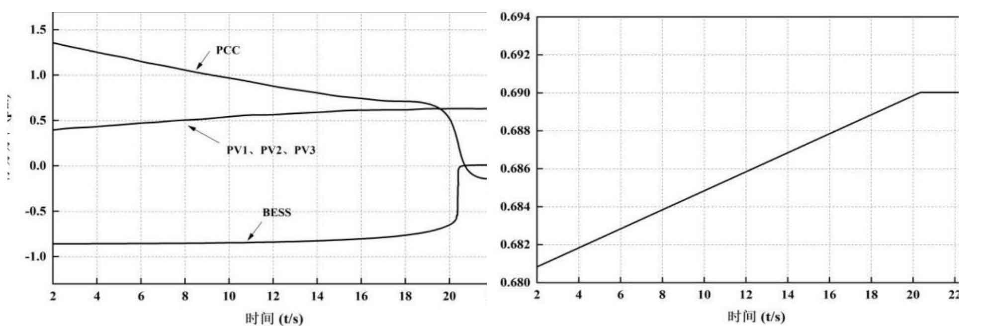
Figure 10 shows the variation of active power in the variable lighting and battery energy storage system under initial charging conditions. Three photovoltaic power generation units have the same power curve with changes in lighting. At the initial moment, three photovoltaic power generation units deliver 0.4 pu of active power to the microgrid, while the main grid delivers 1.4 pu of active power to the microgrid. If the battery energy storage SOC is set to 0.6815 (SOC<SOCmin-L), it is in a charging state. According to the constraint logic of BESS, it is charged at rated power until it reaches the lower limit (SOC=SOCmin=0.69) at t=20.5 seconds, as shown in Figure 11. After this moment, if the battery is in an idle state, the BESS output active power is 0 (the output current is also 0). At the same time, the output active power of the three photovoltaic power generation units is 0.7pu, and at this time, the main grid will no longer transmit active power to the microgrid. Afterwards, the remaining electricity from the microgrid will be output to the main grid.
Figures 12 and 13 respectively show the changes in the voltage and frequency of the grid connection point (VPCC) during the charging process of the energy storage system. The voltage change rate of the microgrid is 1.5%, and the frequency change rate is less than 0.5Hz, both within the normal range, indicating stable system operation.
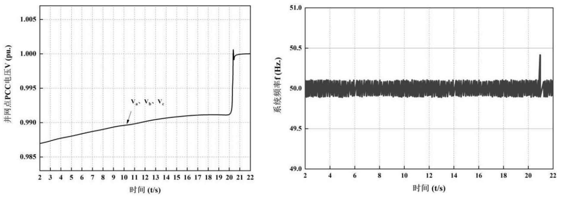
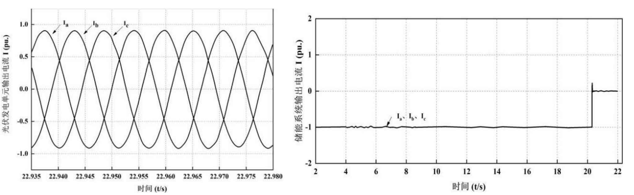
Figure 14 shows that in the control mode of grid connected constant power (P-Q), the three-phase output current of the photovoltaic power generation unit remains balanced. Figure 15 shows that the battery in the energy storage system is initially in a charging state, with an output current of -1pu. At t=20.5, the battery returns to an idle state after charging, and at this point, its output current becomes zero.
5.3 Simulation Analysis of Battery Energy Storage System in Discharge State
Figure 16 Changes in active power in the variable lighting and battery energy storage system under initial discharge conditions. Three photovoltaic power generation units have the same power curve with changes in lighting. At the initial moment, three photovoltaic power generation units transmit 0.4 pu of active power to the microgrid, and the main grid absorbs 0.38 pu of active power from the microgrid. If the battery energy storage SOC is set to 0.769 (SOC>SOCmax H), it is in the discharge state. According to the constraint logic of BESS, the battery is discharged at rated power until it reaches the upper limit (SOC=SOCmax=0.75) at t=17 seconds, as shown in Figure 17. After this moment, if the energy storage battery is in an idle state, the BESS output active power is 0, and the battery output current is also 0. At the same time, the active power output of the three photovoltaic power generation units reached 0.6pu with the change of light intensity, and after this time, the absorption of active power from the main grid to the microgrid significantly decreased.
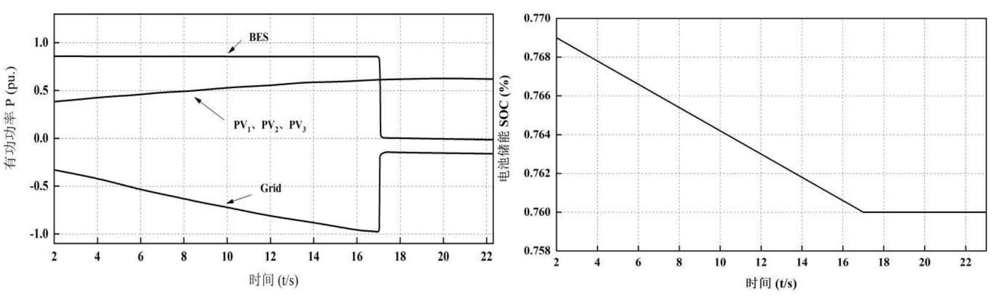
Figures 18 and 19 respectively show the changes in the voltage and system frequency of the grid connection point (PCC) during the discharge process of the energy storage battery. The voltage change rate of the microgrid is 1.05%, and the frequency change rate is less than 1Hz. The stable operation of the system is not affected.
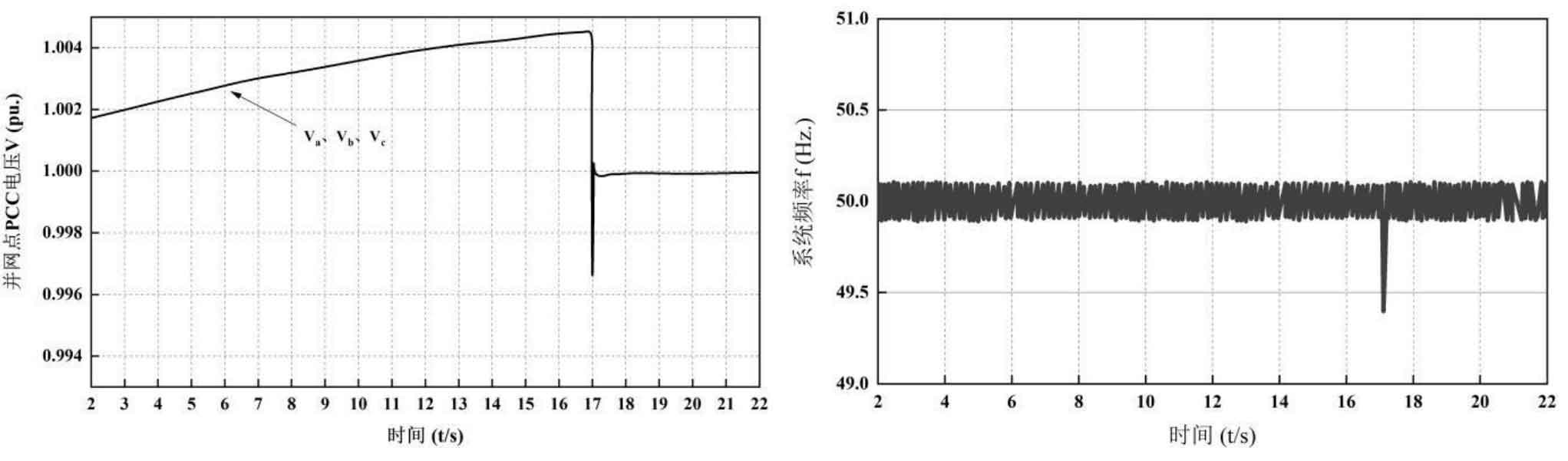
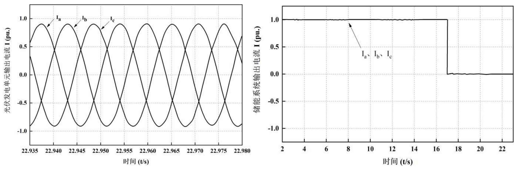
Figure 20 shows the three-phase current balance output by the photovoltaic power generation unit when the battery energy storage system is in discharge under the grid connected constant power (P-Q) control mode. Figure 21 shows that the initial state of the battery in the battery energy storage system is discharge, and the output current of the battery is 1pu. At t=17s, after discharge, it returns to the idle state, and its output current becomes 0.
6. Summary
The control strategy of the microgrid in grid connection mode was explained in detail. The system consists of three photovoltaic power generation units and one set of battery energy storage, which are connected to the main grid. In grid connected mode, the entire optical storage system is in P-Q control mode. The control method of the power generation unit is based on MPPT, and the control method of battery energy storage is based on its SOC constraints, enabling it to perform charging and discharging or be in an idle state during various processes, and avoiding the occurrence of repeated charging and discharging, overcharging or overcharging. The control strategy was simulated and validated under a variable lighting condition. We discussed the operation of the system under three different conditions: battery idle, battery charging, and battery discharge, with a focus on analyzing the changes in active power, voltage, frequency, and current of the system during this process.
According to the voltage standards of the power grid, the sum of the absolute values of positive and negative deviations of power supply voltages of 35kV and above shall not exceed 10% of the rated voltage; For the power grid frequency standard, according to the requirements in the allowable deviation of power system frequency for power quality, the frequency change rate of Class C load must be less than or equal to 1Hz. During this process, the voltage change (VPCC) of the junction point is within 10% (i.e. 0.37% in the first case, 1.5% in the second case, and 1.05% in the third case); The frequency variation of the microgrid is also within 1Hz (i.e. the first case remains unchanged, the second case is less than 0.5Hz, and the third case is less than 1Hz), and the output current of the photovoltaic power generation unit and battery energy storage is always balanced in three phases. This also verifies the correctness and stability of the strategy in grid connection mode.