
Abstract: In order to study the mechanical performance of the down – stayed purlin structure with photovoltaic panels under fire, this paper conducts finite element simulation and analysis. The results show that at normal temperature, the down – stayed purlin can effectively improve the stiffness and bearing capacity of the purlin. Under fire, it can still improve the stiffness, but the improvement of the bearing capacity is limited. Therefore, passive fire protection measures should be taken for the down – stayed purlin. This paper will introduce the research background, finite element model, mechanical performance analysis at normal and fire temperatures, and draw conclusions.

1. Introduction
1.1 Research Background
With the increasing shortage of energy and the growing emphasis on environmental protection, the development and utilization of clean and renewable solar energy have become a global trend. Solar panel installation on the roofs of buildings, especially light steel plants, is a common practice. However, this addition brings challenges to the structural safety of the roof. The increased dead load of the roof due to solar panels may cause the deformation of simply supported purlins to exceed the allowable limits. Moreover, in case of fire, the mechanical performance of the structure is crucial for ensuring the safety of the building and its occupants. Since light steel plant roof purlins are generally not provided with passive fire protection, it is necessary to study the mechanical performance of the down – stayed purlin structure with photovoltaic panels under fire to provide a theoretical basis for the fire – resistant design of such structures.
1.2 Purpose and Significance
The purpose of this study is to understand the mechanical behavior of the down – stayed purlin structure under different conditions, especially under fire, and to evaluate the effectiveness of this structure in improving the performance of the roof. The significance lies in providing guidance for the design and construction of light steel plants with solar panel installations, ensuring the safety and durability of the structure, and promoting the wider application of solar energy in the building industry.
2. Finite Element Model
2.1 Down – Stayed Purlin Structure
The roof purlins of light steel plants are often made of cold – formed thin – walled C – section steel. When the stiffness of the roof panel is large and the connection with the purlin is firm, the overall stability of the purlin may not need to be checked, and the failure mode is considered to be bending failure. To address this, a down – stayed purlin structure is proposed, which consists of two struts at the lower end of the purlin, supported by diagonal and straight tension rods at both ends .
| Component | Specification |
|---|---|
| Purlin | 160 ✖ 70 ✖ 20 ✖ 3 (mm) |
| Strut | 25 ✖ 1.5 (mm) |
| Tension Rod | 8 (mm) |
2.2 Geometric Model
Using the finite element software ANSYS WORKBENCH, a down – stayed purlin structure model is established. The purlin span is 6m, the space height is 20m, and the purlin spacing is 2m. The height of the strut is 0.5m, and the strut spacing is 1/3 of the purlin span, i.e., 2m. The photovoltaic module used is JAM60 285 – PR, with a single – piece plane size of 1650mm ✖ 991mm ✖ 40mm and a weight of 0.13kN/m^2. According to the building structure load code, the dead load is 0.5kN/m^2, the live load is 0.5kN/m^2, and the wind load is not considered. The equivalent uniform line load design value applied to the purlin is 2.26kN/m. The model components are all Beam elements, and the connections are rigid. The support conditions are hinged at both ends of the purlin.
2.3 Fire Source Model
Since the main structures requiring down – stayed purlin structures are light steel plants with a height of more than 10m and often adopt a portal frame or bent frame system, which belongs to a large space, the indoor temperature rise does not conform to the standard temperature rise curve ISO834. In this paper, a practical air temperature rise empirical formula for large – space building fires obtained by Li Guoqiang is used. The fire power is considered as 5MW, and the fire speed is medium. The formula is as follows:
T(m,h,t)-Ts(0)=
where T(m,h,t) is the air temperature (°C) at a horizontal distance from the fire source center and a vertical distance h(m) from the ground at time t; Ts(0) is the indoor initial temperature, which can be set as 20°C; Th is the maximum air temperature at a vertical distance h(m) from the ground; δ is the temperature rise curve coefficient determined by the fire power and growth rate; ν is the distance between the outermost edge point and the center point of the fire source; φ is the temperature attenuation coefficient (dimensionless), and when x<v , it is taken as 1.
The fire source is located on the ground, and the center of the fire source coincides with the center of the purlin. The temperature field distribution of the down – stayed purlin structure during the fire heating process is obtained through the above formula. The temperature field distribution of the purlin after heating for 60 minutes.
2.4 Material Properties of Steel at High Temperatures
The purlins and struts of the down – stayed purlin structure are made of Q235 ordinary steel, and the tension rods are made of HRB400 grade steel. At normal temperature, the yield strength of Q235 ordinary steel is 235MPa, and that of HRB400 steel is 360MPa. The elastic modulus is 206000MPa. The linear expansion coefficient of Q235 ordinary steel at high temperatures is , the density is , and the Poisson’s ratio is 0.3. The thermodynamic parameters of the steel at different temperatures are shown in Table 2. The constitutive relationship adopts an ideal elastoplastic model.
| Temperature () | Yield Strength (MPa) | Elastic Modulus (MPa) | Thermal Conductivity () | Specific Heat Capacity () |
|---|---|---|---|---|
| 20 | 235 | 206340 | 53.3 | 439.8 |
| 50 | 235 | 206143 | 52.3 | 459.7 |
| 100 | 235 | 204245 | 50.7 | 487.6 |
| 150 | 235 | 201333 | 49.0 | 510.4 |
| 200 | 235 | 197900 | 47.3 | 529.8 |
| 250 | 235 | 193910 | 45.7 | 547.3 |
| 300 | 235 | 188795 | 44.0 | 564.7 |
2.5 Temperature Rise Calculation of Steel Members
The heat transfer between the ambient air and the steel members mainly occurs through heat radiation and convection, and there is also heat conduction within the steel members due to the temperature difference. The temperature rise calculation formula of the steel members given by the European code EC.3, which has a relatively conservative calculation result, is adopted as follows:
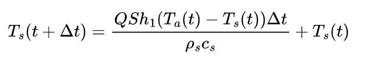
where Q is the correction coefficient considering the influence of the fire smoke shadow, taken as 1.0; S is the surface coefficient of the steel member, equal to the ratio of the surface area to the volume of the steel member; h1 is the design value of the net heat flux per unit area; Tα(t) is the air temperature near the steel member at time t ; Ts(t) is the temperature of the steel member at time t, and when t=0, it is taken as 20°C; to ensure the accuracy of the incremental calculation, Δt does not exceed 5s.
The improved calculation formula for the design value of the net heat flux per unit area h1 given by Zheng Yongqian is as follows:
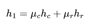
where μc and μr are safety coefficients, taken as 1.0 and 0.15 respectively; hc is the heat flow transferred in the form of heat convection, and its value is hc=bc(Ta-Ts); is the convective heat transfer coefficient, taken as 25W/m^2•°C. The heat flow transferred in the form of heat radiation hr can be calculated as follows:
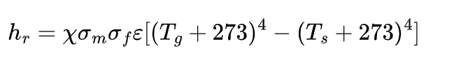
where ✖ is the shape coefficient, taken as 1.0; σm is the radiation coefficient related to the surface shape of the steel member, and for the unprotected steel member surface, it is taken as 0.3; σf is the radiation coefficient related to the fire room, usually taken as 0.8; is the blackbody radiation constant, with a value of 5.67 ✖ 10^-8W•m^-2•K^-4.
3. Mechanical Performance Analysis at Normal Temperature
3.1 Simply Supported Purlin
According to the provisions of the “Steel Structure Design Standard”, the maximum deflection of the roof purlin under the standard load should not exceed L/150 (L is the purlin span). In this model, the purlin span is 6m, so the allowable maximum deflection is 40mm. The displacement and stress distributions of the simply supported purlin at normal temperature.
From the displacement of the simply supported purlin, it can be seen that at normal temperature, under the vertical load, the displacement in the middle of the purlin span is the largest, with a maximum displacement of 48.59mm, which exceeds the allowable maximum deflection of the purlin. Therefore, the deformation of the simply supported purlin after adding the solar panel does not meet the requirements at normal temperature. From the stress of the simply supported purlin, it can be seen that at normal temperature, under the vertical load, the stress at the purlin support is greater than that in the middle span region, with a maximum stress of 119.03MPa, which does not exceed the yield strength of 235MPa at normal temperature, so the member will not yield. This indicates that the deformation of the simply supported purlin is the key factor affecting the safety of the purlin at normal temperature.
3.2 Down – Stayed Purlin
When the simply supported purlin has a large deformation that is not suitable for continuous bearing, the down – stayed purlin can be used to improve the stiffness and bearing capacity. The displacement and stress distributions of the down – stayed purlin at normal temperature.
From the displacement of the down – stayed purlin, it can be seen that at normal temperature, under the vertical load, the displacement of the tension rod is the largest, with a maximum displacement of 37.12mm; the displacement of the purlin decreases, and the maximum displacement in the middle span region of the purlin is 14.50mm, which does not exceed the allowable maximum deflection of the purlin, indicating that the use of the down – stayed purlin for reinforcement can effectively improve the stiffness of the purlin. From the stress of the down – stayed purlin, it can be seen that at normal temperature, under the vertical load, the stress at the support of the down – stayed purlin is greater than that in the middle span region, with a maximum stress of 98.27MPa, which does not exceed the yield strength of 235MPa at normal temperature and is lower than the maximum stress generated by the simply supported purlin at normal temperature, indicating that the use of the down – stayed purlin for reinforcement can effectively improve the bearing capacity of the purlin.
4. Mechanical Performance Analysis under Fire
4.1 Simply Supported Purlin
The fire resistance of the steel structure is poor, and generally, the roof purlin is not provided with passive fire protection. Therefore, it is necessary to analyze the mechanical performance of the roof purlin under fire. The displacement and stress of the simply supported purlin under fire continue to increase, and the stress reaches the maximum at 1800s. The displacement and stress distributions of the simply supported purlin at 1800s under fire.
From the displacement of the simply supported purlin, it can be seen that under fire, the displacement response of the roof purlin under the vertical load continues to increase, and the displacement in the middle span is the largest. At 1800s, the maximum displacement reaches 53.61mm, exceeding the allowable maximum deflection of the purlin. From the stress of the simply supported purlin, it can be seen that under fire, under the vertical load, the stress at the support of the purlin is greater than that in the middle span region. The maximum stress reaches the yield strength of 235MPa at 1300s, and then the local stress of the purlin slightly increases, reaching a maximum of 248.02MPa, and the purlin fails.
4.2 Down – Stayed Purlin
The displacement and stress distributions of the down – stayed purlin under fire.
From the displacement of the down – stayed purlin, it can be seen that under fire, under the vertical load, the displacement of the tension rod of the down – stayed purlin increases rapidly, with a maximum displacement of 122.94mm at 1800s, while the displacement of the purlin increases slowly, with a maximum of only 37.70mm, which does not exceed the allowable maximum deflection of the purlin, indicating that the use of the down – stayed purlin for reinforcement can still effectively improve the stiffness of the purlin under fire. From the stress of the down – stayed purlin, it can be seen that under fire, under the vertical load, the stress at the support of the purlin is greater than that in the middle span region. The maximum stress reaches the yield strength of 235MPa at 1500s, which is 200s later than that of the simply supported purlin. Then, the local stress of the purlin slightly increases, reaching a maximum of 242.76MPa at 1800s, and the purlin fails. This indicates that the reinforcement of the down – stayed purlin under fire cannot effectively improve the bearing capacity of the purlin. Comprehensive analysis of the displacement and stress responses shows that the reinforcement of the down – stayed purlin under fire can effectively improve the stiffness of the purlin, but the improvement of the bearing capacity is limited.
5. Conclusions
- At normal temperature, adding solar panels to the roof will cause the simply supported purlin to have a large deformation that is not suitable for continuous bearing. By using the down – stayed purlin for reinforcement, the stiffness and bearing capacity of the purlin can be effectively improved.
- Under fire, the displacement of the simply supported purlin increases rapidly and exceeds the allowable maximum deflection of the purlin, while the displacement of the down – stayed purlin develops slowly, indicating that the use of the down – stayed purlin for reinforcement can still effectively improve the stiffness of the purlin under fire.
- Under fire, although the use of the down – stayed purlin can effectively improve the stiffness of the purlin, the improvement of the bearing capacity is limited. Therefore, for the roof reinforced with the down – stayed purlin, passive fire protection measures should be taken for the down – stayed purlin, such as painting fire – retardant paint, to ensure that the down – stayed purlin can effectively play its role.
In summary, this study provides a theoretical basis and practical guidance for the design and application of the down – stayed purlin structure with solar panels in light steel plants, especially in terms of fire safety considerations. Future research can focus on further optimizing the structure and exploring more effective fire protection methods to enhance the overall performance and safety of such structures.