
In recent years, renewable energy has received widespread attention due to its environmental characteristics. Micro power sources such as photovoltaics and wind turbines are connected to the microgrid system through inverters. If the microgrid is connected to the large grid, it is called grid connection mode, which corresponds to island mode. Island microgrids can solve the problem of electricity consumption in remote areas where power grids cannot be installed. The solar island microgrid is composed of photovoltaic panels, maximum power point tracking (MPPT) equipment, DC/DC bidirectional converters, voltage source inverters, undamped filters, step-down transformers, and loads. At present, there are still many problems to be solved in the operation of island microgrids, on the one hand, due to the impact of changes in solar irradiance and environmental temperature on the system. Therefore, it is necessary to introduce energy storage systems in conjunction with photovoltaic systems to form a master-slave microgrid.
At present, the main control methods for inverters include proportional reset (PR) control, repetitive control, double hysteresis control strategy, droop control, predictive control, sliding mode control, etc. Quasi PR control can achieve tracking control without static errors and has strong robustness. The disadvantage is that the dynamic performance will decrease as the system bandwidth decreases. Repetitive control is based on the principle of internal model control and has the ability to suppress periodic disturbances, but its dynamic response speed is slow. Double hysteresis control is a nonlinear control with extremely fast response, but the loop width adjustment is complex and hardware implementation is difficult. As the scale of distributed power sources continues to expand, droop control can be used to achieve synchronous generator characteristic control. However, its controller is based on PI control method and there are voltage and frequency regulation deviations. A two-layer model predictive control based on DC microgrid is proposed, which can reduce operating costs and improve system adaptability. Sliding mode control has the ability to suppress disturbances and exhibits strong robustness to changes in model parameters. By combining sliding mode control technology with active disturbance rejection technology and replacing feedback control and disturbance compensation with sliding mode control, the anti-interference ability of the control system can be improved. The switching gain of sliding mode control can cause chattering phenomenon, and power electronic devices need to be frequently turned on and off, while requiring the inverter to inject as little current harmonics into the system as possible. Therefore, an improved sliding mode reaching law is introduced to reduce the system’s chattering on the sliding mode surface and have stronger resistance to load disturbances. Designed an adaptive terminal sliding mode controller. The terminal sliding mode controller accelerates convergence speed and reduces sliding mode chattering while ensuring system stability. However, it requires the introduction of a signal differentiator to obtain the sliding mode surface and its derivative signals in the terminal sliding mode control law. A second-order sliding mode differentiator was introduced to filter the intermediate virtual control variable and calculate its derivative value, effectively reducing waveform distortion caused by load switching and making the transition current smoother.
A model parameter adaptive control is described, which uses parameter adaptive estimation values to replace model parameters and uses adaptive sliding mode control to counteract disturbances. Combined with backstepping, a Lyapunov function is constructed using estimation errors and a control law is derived. Sliding mode control with adaptive estimation can effectively suppress output current waveform distortion caused by load disturbances and parameter perturbations. However, according to the Lyapunov like lemma, this method cannot guarantee the convergence of parameter estimation errors and accurate identification of model parameters. Apply a fractional order sliding mode controller to the inverter and perform output voltage tracking control.
In summary, this article designs a new anti disturbance backstepping super twisting sliding mode controller (ADB-SSMC) for solar inverters in master-slave island microgrids, which is used to stabilize the DC side voltage and control the output power of photovoltaic systems. The controller introduces parameter estimation based on Lyapunov stability theory, and the projection adaptive algorithm ensures that the estimated values are bounded. Finally, Lyapunov stability proof was performed on the global control variables, ensuring the reachability of sliding mode dynamics and bounded convergence of estimation errors. The simulation results verified the effectiveness of the controller.
1. Dynamic model of solar inverters
The bipolar three-phase photovoltaic power generation system includes photovoltaic (PV) cells, MPPT controllers, DC side capacitors Cdc, voltage source converters (VSCs), resistive filters, and phase locked loops (PLLs). The output voltage of VSC is connected to the AC bus through a step-up transformer, and then supplied to the load after being reduced by the transformer. The filtering capacitor Cdc is connected in parallel on the DC side of the VSC to reduce the output voltage ripple. R and L represent the equivalent resistance and inductance of the filter, respectively. The variables uabc, iabc, and ukabc represent the filter terminal voltage, filter current, and VSC output voltage, respectively. Uabc and iabc are converted into dq components through the parker transform, and control operations are completed in the dq rotating coordinate system. control signal τ Dq is transformed into τ ABC generates a VSC control signal through pulse width modulation (PWM). The structural model of a bipolar three-phase photovoltaic power generation system is shown in Figure 1.
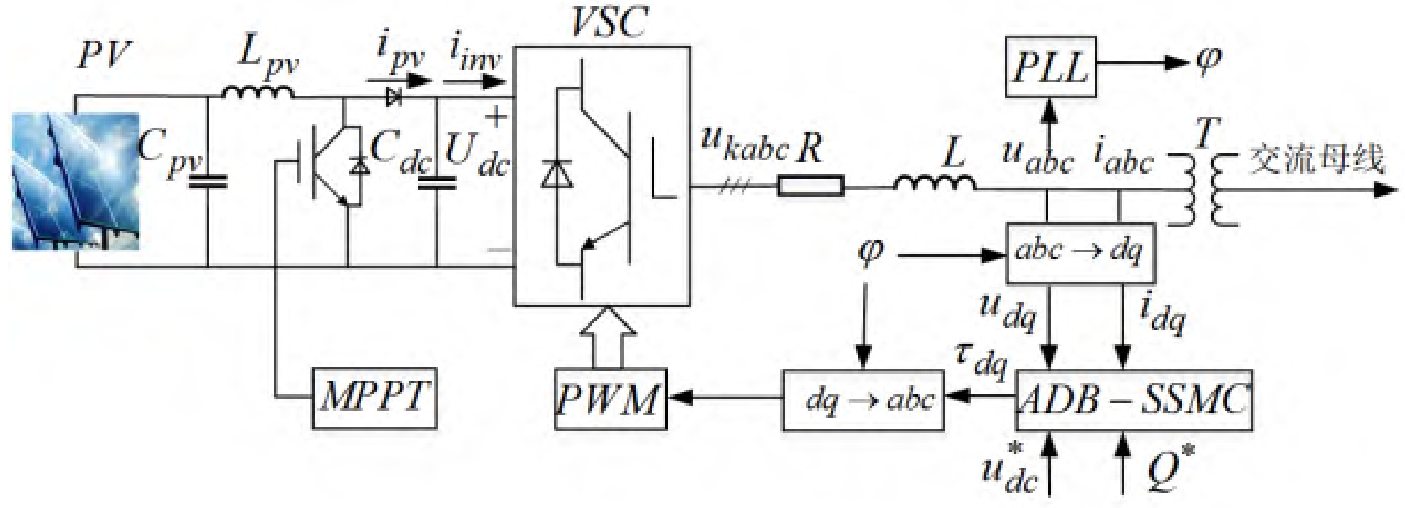
According to the Kirchhoff voltage and current theorem, the VSC circuit in Figure 1 is mathematically modeled as:
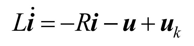
In the equation, i, u, and uk are abc i, abc u, and kabc u vectors, respectively. And uk can be expressed as uk=(dc u/2)* τ , Among them, τ PWM control signal. By converting the three-phase stationary space vector in equation (1) to the dq rotating coordinate system, it can be obtained that:
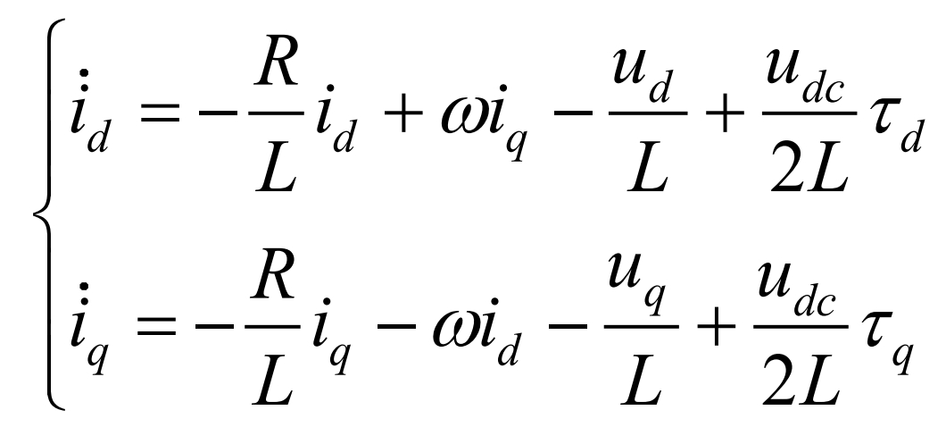
In the equation, ω Is the rotational angular velocity of the dq coordinate system. The DC side udc, ipv, and iinv of photovoltaic systems can be expressed as:
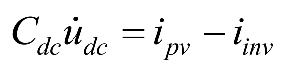
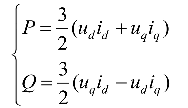
In the formula, ipv represents the output current of the boost circuit, iinv and udc represent the DC side current and voltage of the solar inverter, respectively. In the dq coordinate system, the active and reactive power of the PV system can be expressed as:
Ignoring the power consumption of the solar inverter circuit, the DC side power and VSC output power of the PV system can be written as:
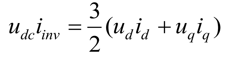
Substitute the formula and eliminate the variable iinv to obtain:
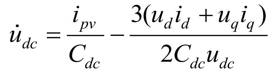
Considering the uncertainty of solar radiation and environmental temperature, the lumped term for the unmodeled part of the system and external disturbances is defined as d. Therefore, the dynamic model of the system is written as:
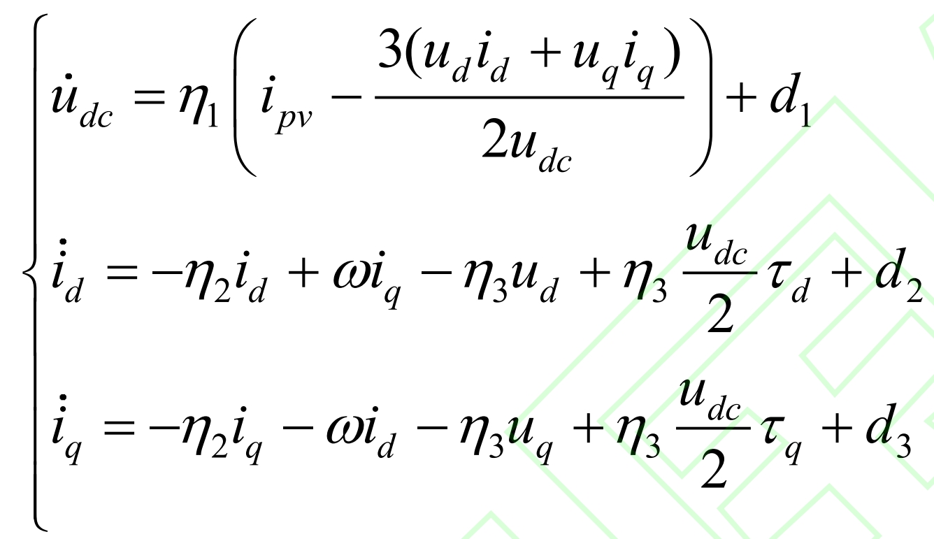
In the equation, η 1=1/Cdc η 2=R/L η 2=1/L.
2. Design of a backstepping hyper spiral sliding mode controller with high-order sliding mode differentiator
2.1 Design of voltage outer loop controller
Set circuit parameters η The adaptive estimation error for i (i=1,2,3) and disturbance parameter di (i=1,2,3) is:
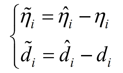
In the equation, ˆη I ˆ Di are respectively η i. The adaptive estimation values of di and their adaptive laws are defined in the formulas. The tracking error of the DC side capacitor voltage is defined as:
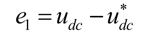
In the formula, u * dc is the reference voltage on the DC side. Construct the Lyapunov function V1=e1 ^ 2/2 and take the derivative of V1:
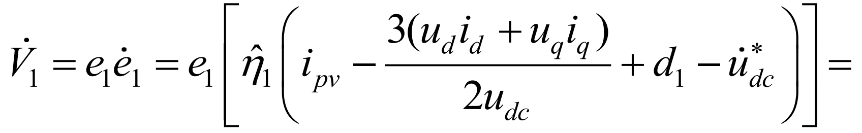
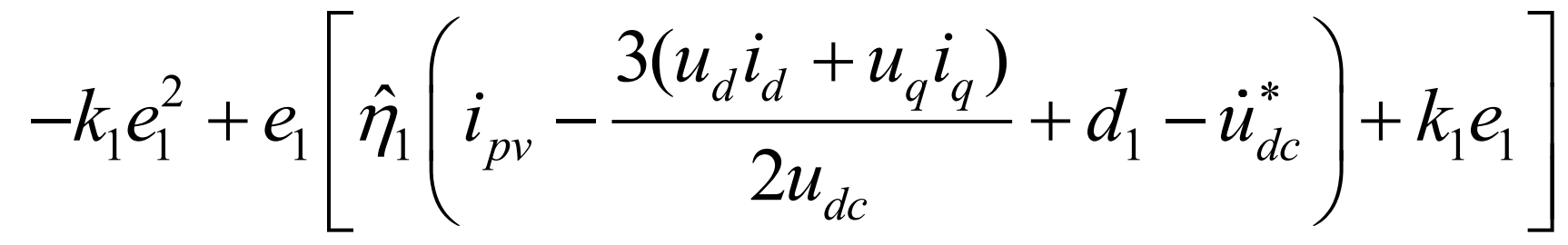
In the equation, k1 is a normal number, and according to Lyapunov’s theorem, the derivative of V1 needs to be negative definite. Therefore, the virtual control quantity considered for adaptive estimation in combination with backstepping design is:
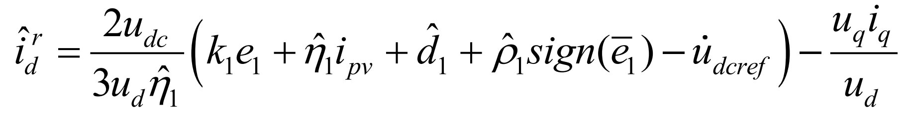
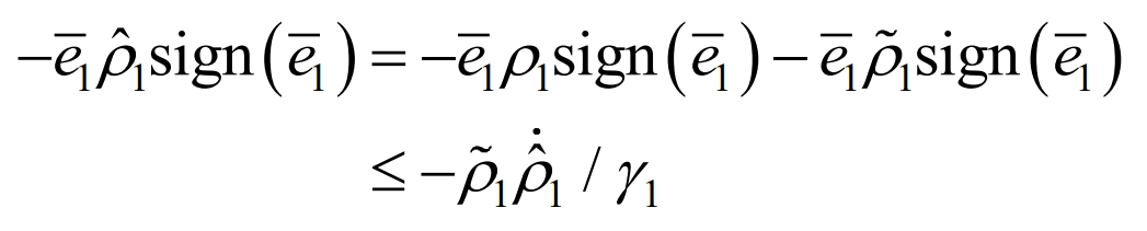
In the formula, the symbol function is specifically defined as sign (x), ρ 1 is the error bound for d1 adaptive disturbance estimation, and satisfies| ˆ D1 | ≤ ρ 1, ρ The adaptive law for the estimated value of 1 is:
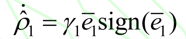
In the equation, ˆ E1=e1- σ,σ Defined in the formula. When using the backstepping method in nonlinear systems, taking the derivative of the intermediate virtual control variable can cause computational expansion, and there is often high-frequency noise interference in actual circuits, making it difficult to accurately obtain the signal derivative value. Therefore, the Levant high-order sliding mode differentiator (HOSMD) is introduced. Under the conditions of satisfying Lebesgue measurable sampling noise, HOSMD has high-performance filtering and the ability to obtain input signal derivatives. To ensure the accuracy of the sliding mode differentiator and take into account the calculation time, the order of HOSMD is selected as 3, and the specific expression is:
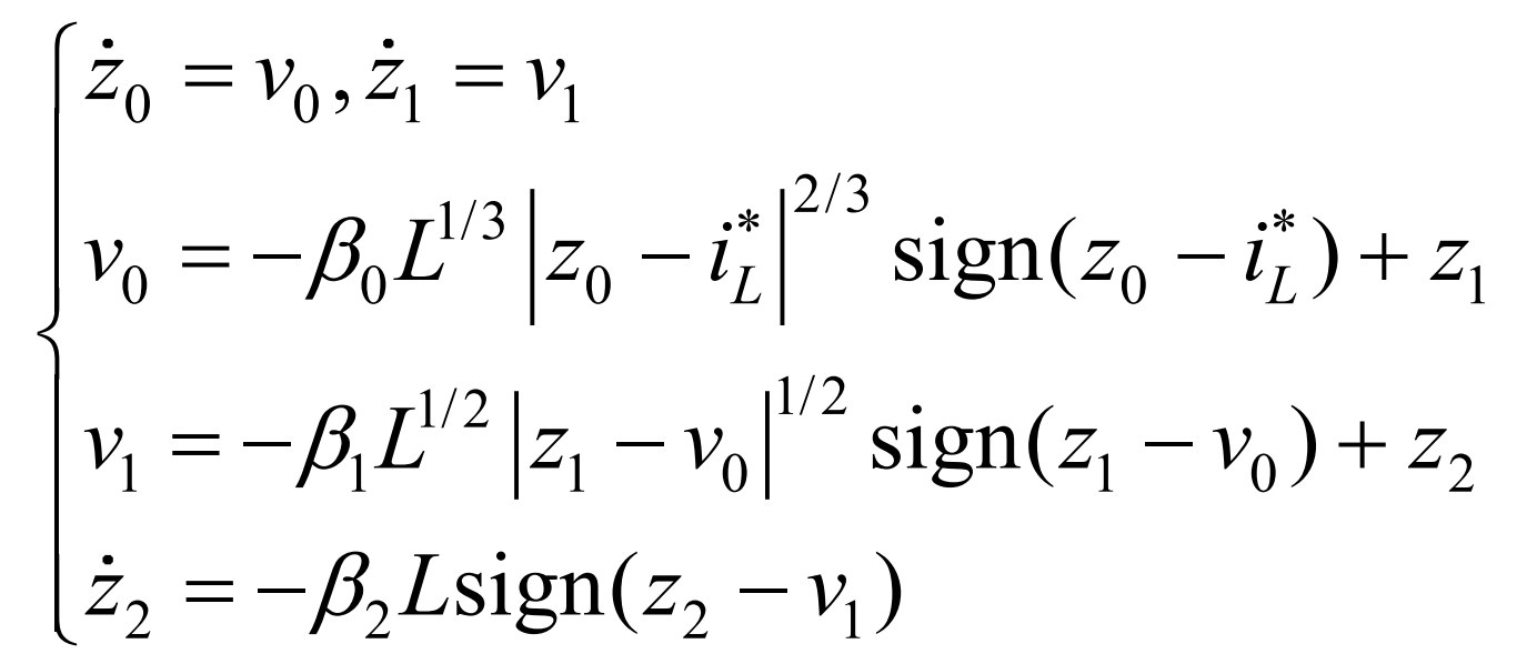
In the formula, i * L is the HOSMD input signal, which is the virtual control quantity ˆ Ird. Z0=i * d is the output signal, and z1=v0 is the derivative of the output signal. select β 0 β 1 and β The value of 2 will converge after a finite time.
Define HOSMD error compensation amount σ For:
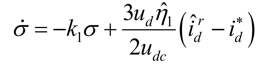
Combining the formula to derive e1:
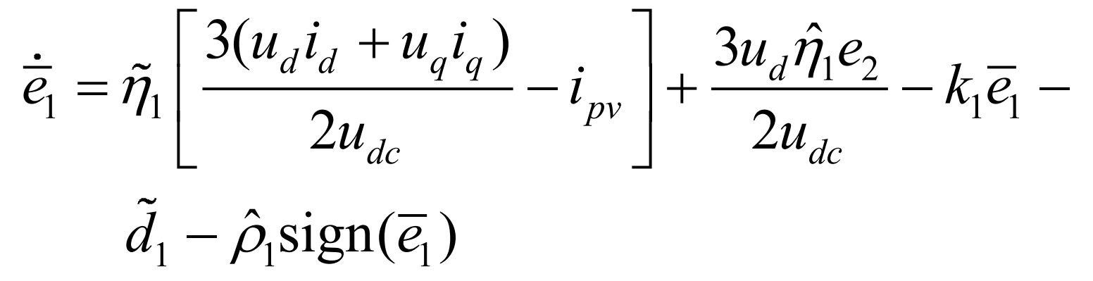
In the equation, e2 is defined in the formula. To stabilize e1, select V2= ˆ E1 ^ 2/2 is the Lyapunov function, taking the derivative of V2:
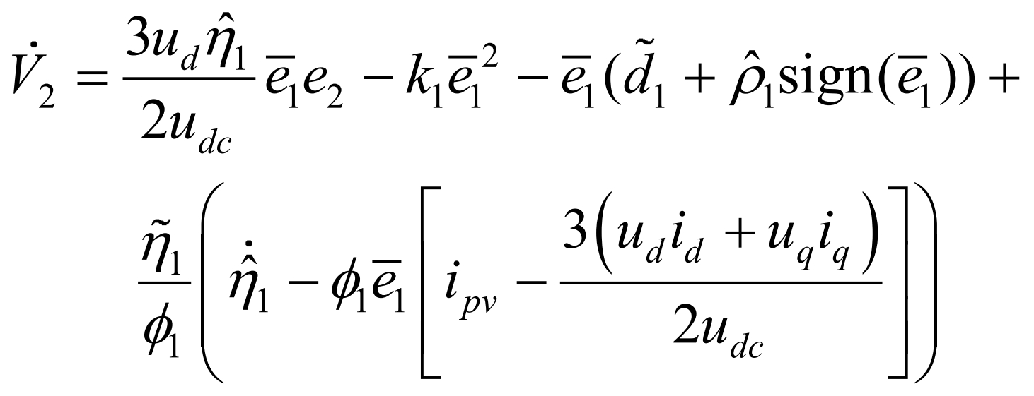

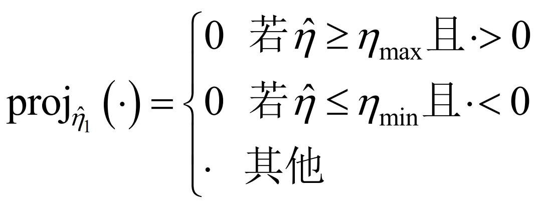
In the equation, α Inertia constant 1>0 to ensure accurate convergence of adaptive estimation. The use of projection adaptive algorithms is to prevent ˆη 1 too large causing controller saturation or ˆη Control Singular Problem at 1=0, proj ˆη1 (·) expression for is:
2.2 Design of Current Inner Loop Controller
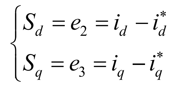
To improve the power factor, I * q is set to 0. The tracking error and sliding mode surface of the current inner loop id and iq are defined as:
The super helix sliding mode algorithm (STA) is a second-order sliding mode control algorithm. For bounded disturbances, the super helix sliding mode control can make the sliding surface s converge to the set point in a finite time and effectively reduce chattering. The control law of the current inner loop is controlled by equivalent control τ EQ and Hyperspiral Control τ St composition. Based on the combination of Sd=0 and the formula τ Deq is:
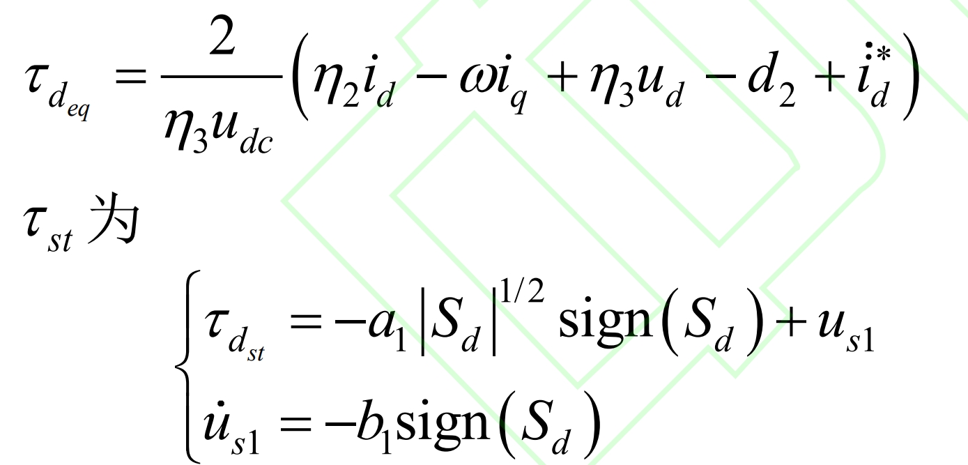
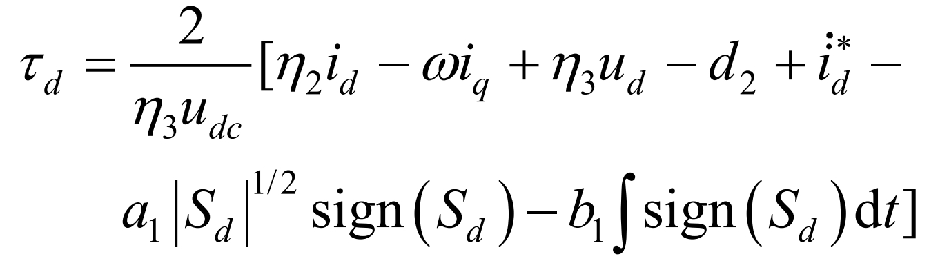
In the equation, α 1. B1>0, α The 1 | sd | ^ 1/2 sign (sd) term can suppress disturbances and has a variable switching gain, reducing the chattering amplitude of sliding mode control while improving controller robustness. Us1 is the integration of the discontinuous control variable bsign (sd), and compared with first-order sliding mode control, the continuous control variable us1 has a significant reduction in chattering effect. By the overall control law τ = τ Eq+ τ St obtained:
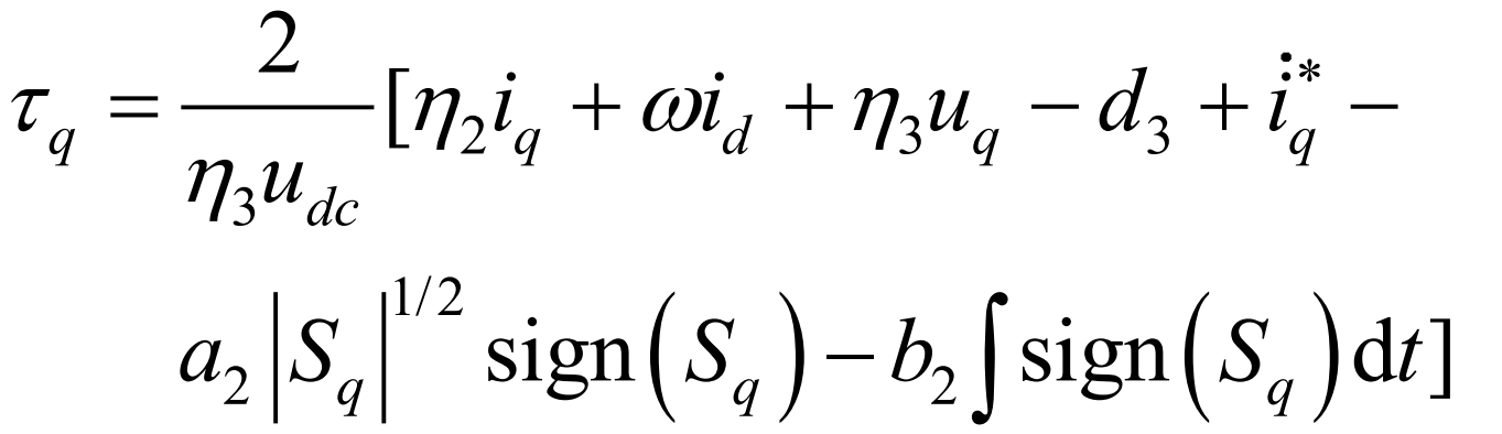
Similarly, it can be concluded that τ Q is:
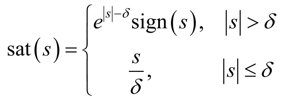
Using an improved saturation function sat (s) instead of the sign function sign (s) for switching control outside the sliding mode boundary layer can effectively reduce the chattering of sliding mode control. set up δ The sat (s) function is defined as:
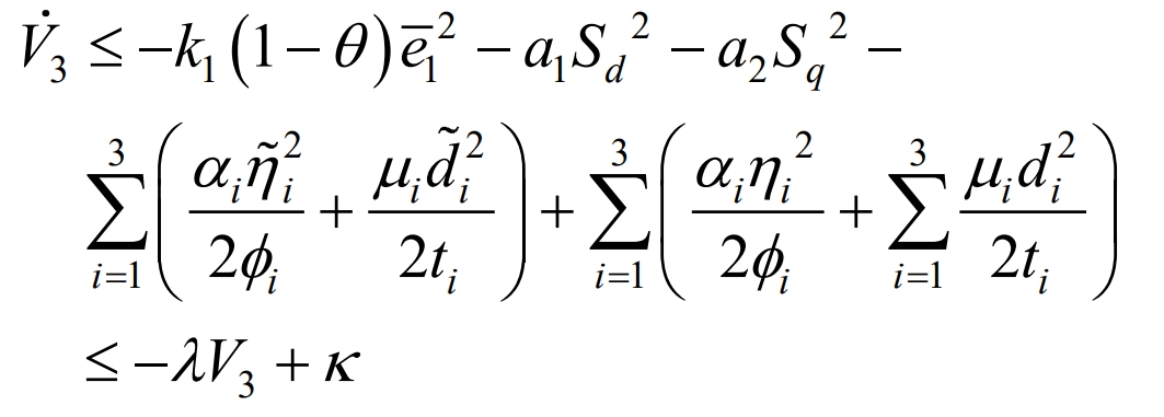
To stabilize the system and constrain adaptive estimation errors, the Lyapunov function V3 is defined as:
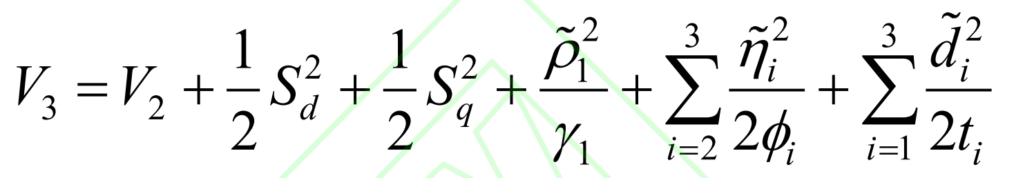
In the equation, γ 1 φ Both k and ti are adaptive parameters greater than zero, and the derivative of V3 is obtained by combining the formula:
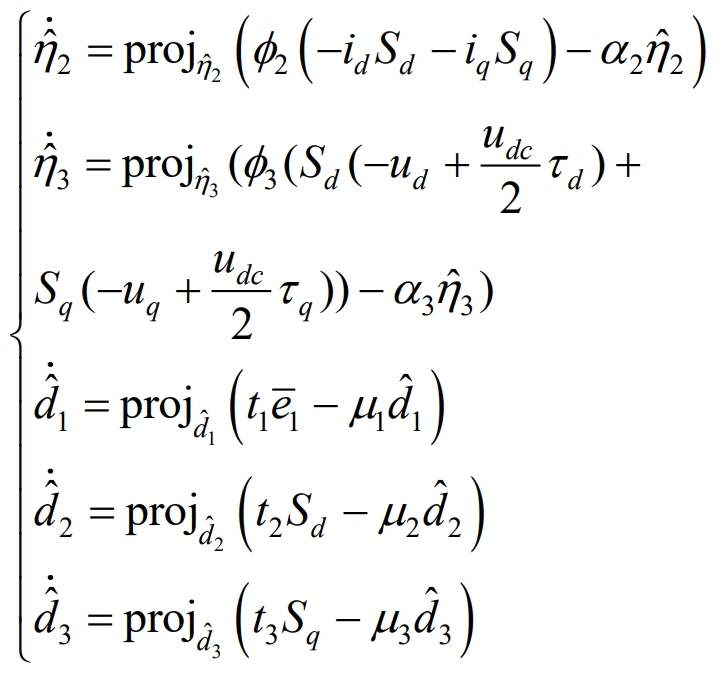
order ˆη 2 ˆη 3 and ˆ The adaptive law of di (i=1,2,3) is:
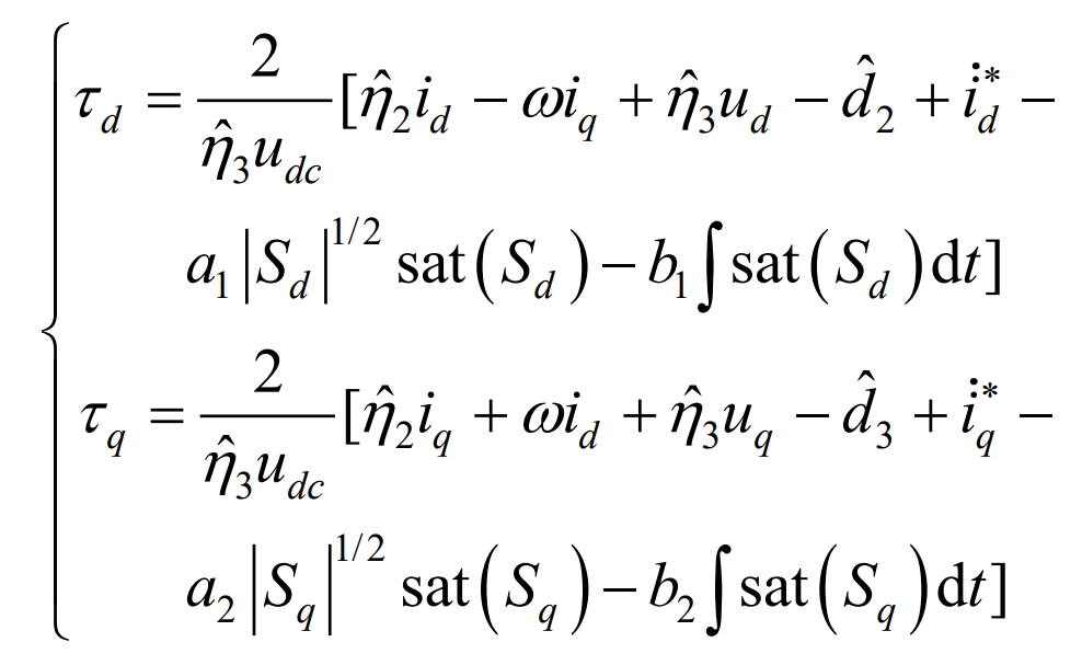
In the equation, α 2, α 3>0 μ I>(i=1,2,3). According to the Lyapunov stability theorem, the controller is designed as follows:
3. Controller stability analysis
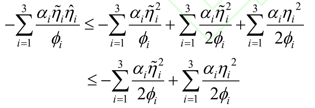
Substituting the formula into it, according to the properties of the projection adaptation theorem, it can be obtained that:
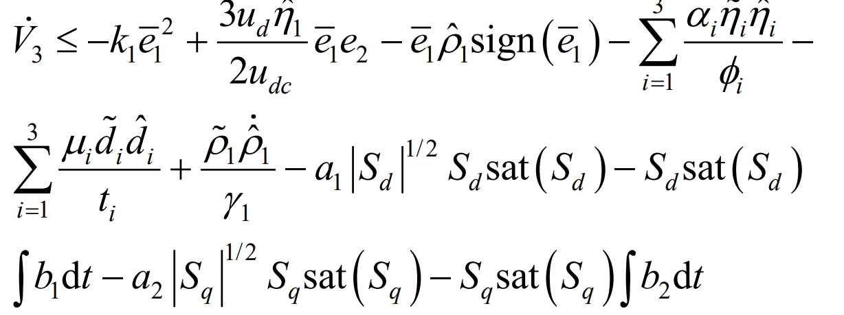
Obtained:
In addition, to eliminate coupling terms, define 0< θ < 1 result:
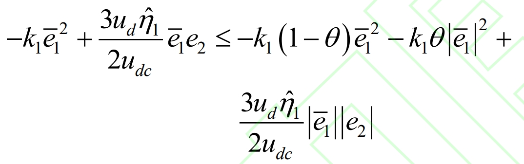
By selecting appropriate parameters, the coupling term can be eliminated. Therefore, based on the basic inequality, it can be proven that:
Similar:
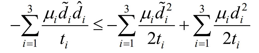
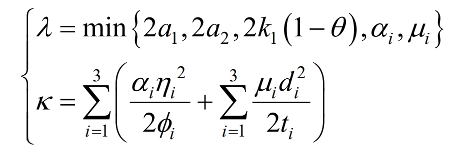
Substituting the formula and combining it with the definition of sat (s), it can be concluded that:
In the equation, λ 、κ For:
Lemma 1:
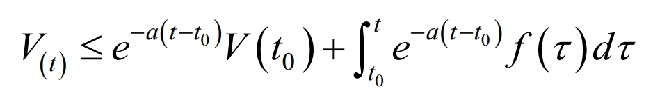
From Lemma 1, it can be concluded that:
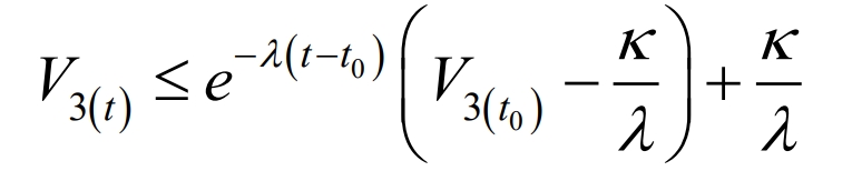
Then:
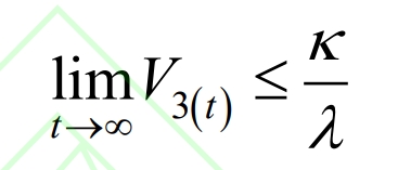
When V3 (t)> κ/λ When V3 (t) is negative definite, therefore, V3 (t) will asymptotically converge to a bounded domain, satisfying the reachability of sliding mode dynamics. The convergence of both disturbance estimation error and adaptive parameter estimation error depends on λ and κ 。
4. Simulation experiments and analysis
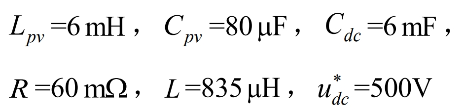
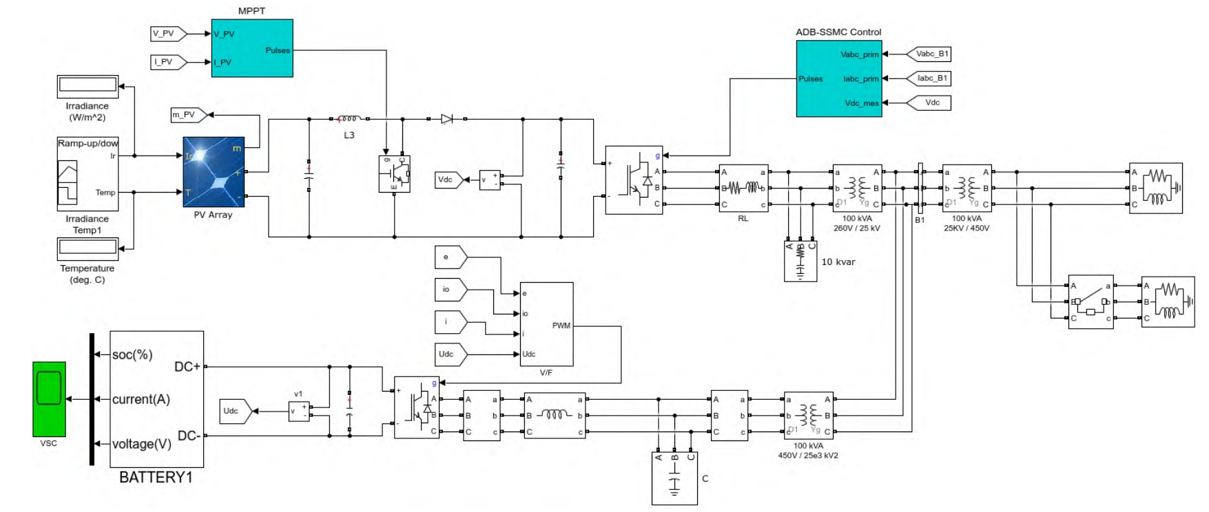
Build a master-slave islanded optical storage microgrid system with a rated power of 100kW using Matlab/Simulink simulation platform. On the DC side of the energy storage system (ESS), the energy storage battery is connected to the solar inverter through a bidirectional Buck Boost circuit, and the output end of the solar inverter is connected to the public AC bus through a transformer. The solar inverter of the energy storage system adopts v/f control, which differs from the control of the solar inverter in that the dq conversion is provided with a rotation angle by a voltage frequency oscillator φ 。 An anti disturbance backstepping terminal sliding mode control (ADB-TSMC) was designed and compared with the designed controller. The main model parameters of the PV system are:
The entire simulation process of the step-up transformer Tb: 260V/25kV (line voltage) lasts for 2 seconds. In order to simulate intermittent characteristics such as local shadows and ambient temperature fluctuations in photovoltaic power generation, lighting intensity (Ir) and temperature (T) curves are used to replace actual environmental changes. When t<0.3 s, Ir=1000W/m2. When t ∈ (0.3,0.5] s, Ir decreases uniformly from 1000W/m2 to 400W/m2, and after holding for 0.1s, it rises uniformly to 1000W/m2 within t ∈ (0.7,0.9] s and remains until the end of the simulation. When t<1s, T=25 ℃, and when t ∈ (1,1.25] s, T increases uniformly from 25 ℃ to 60 ℃. Within t ∈ (1.25,1.5] s, T decreases uniformly to 25 ℃ and remains until the end of the simulation. The specific simulation system structure is shown in Figure 2.
To verify the impact of load changes on the system, when t=1.6s, the load increases from 80kW to 140kW. Take the error between the simulation model and the mathematical model as the disturbance set term d. In order to verify the effectiveness of adaptive parameter identification when filter parameters (such as inductance and resistance) are perturbed, within 1.62 seconds to 1.92 seconds, the filtering resistance on the solar inverter side uniformly increases from 0.06 Ω to 0.061 Ω, and the filtering inductance also increases from 835 Ω μ H uniformly descends to 830 μ H. The controller parameters are selected as:
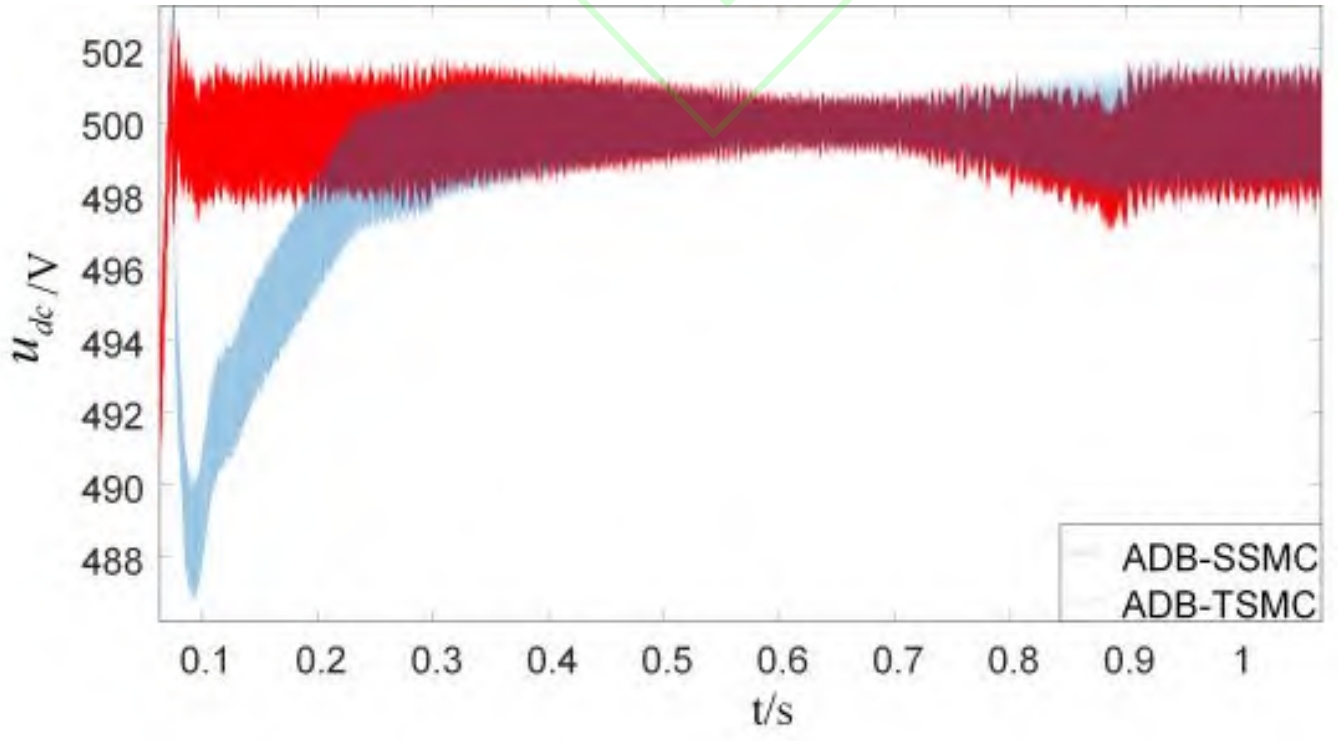
The ADB-SSMC controller has small tracking error of DC side capacitor voltage and short initial transient time. When the light intensity and temperature change, the voltage can be maintained near the reference value, with a fluctuation amplitude of less than 5V, and has strong resistance to external disturbances. Compared to ADB-TSMC, ADB-SSMC has faster convergence speed and shorter transient time. The comparison of DC side voltage tracking effects between ADB-SSMC and ADB-TSMC is shown in Figure 3.
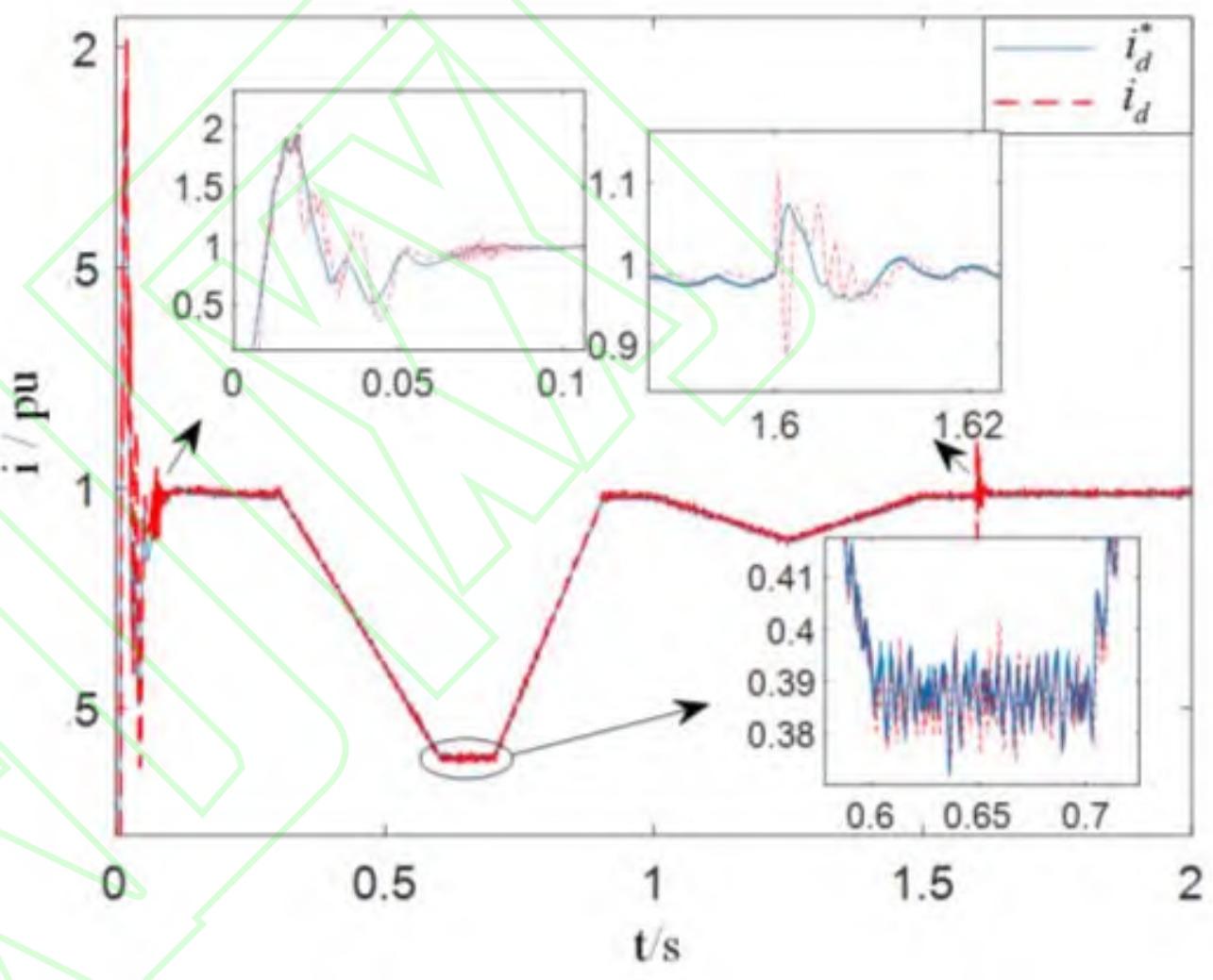
The ADB-TSMC controller can quickly respond to fluctuations in load and photovoltaic power supply. Due to the intermediate virtual control quantity, the ADB-TSMC controller can quickly respond to fluctuations in load and photovoltaic power supply ˆ After being filtered by HOSMD, the jitter of i * d is reduced, and the current tracking accuracy is high in steady-state. The variation curve of the ADB-SSMC control inner loop current id and its reference value is shown in Figure 4.
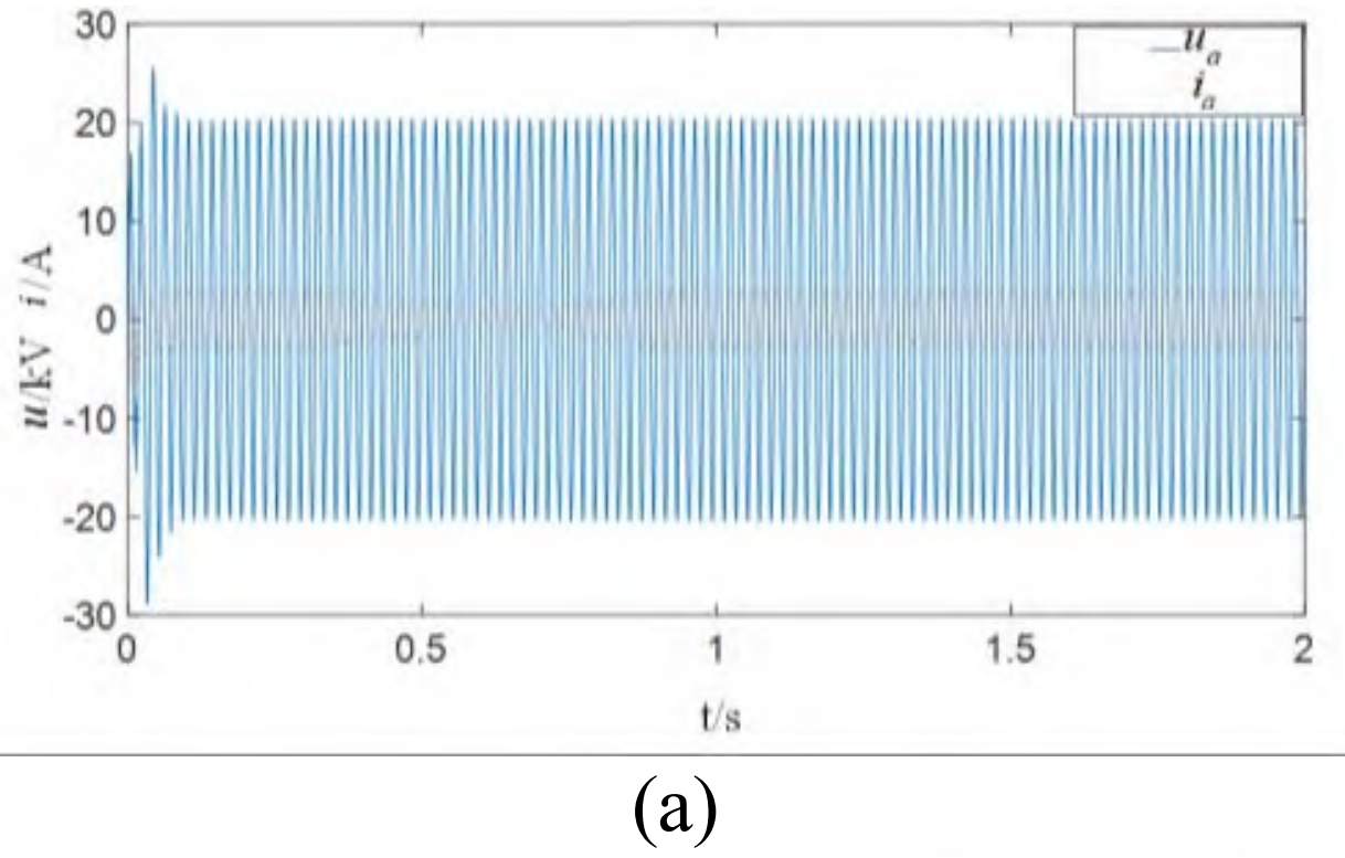
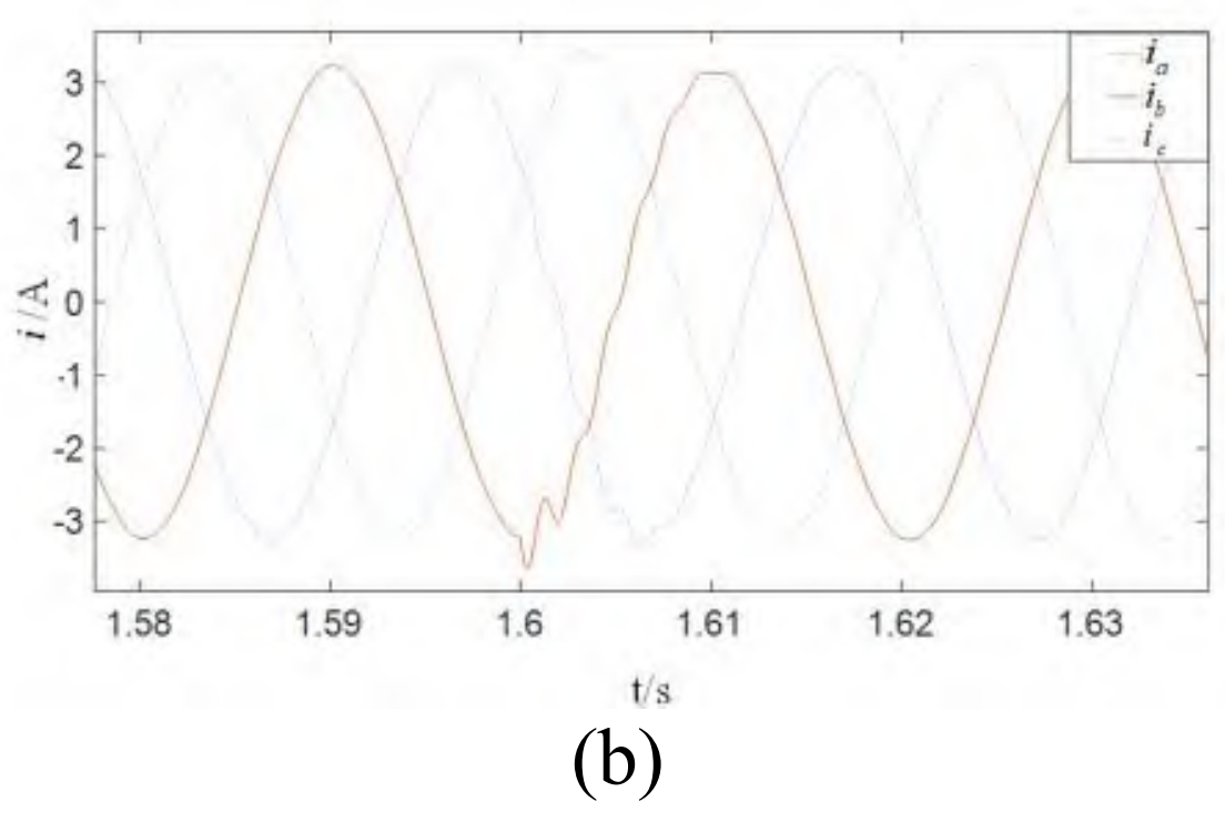
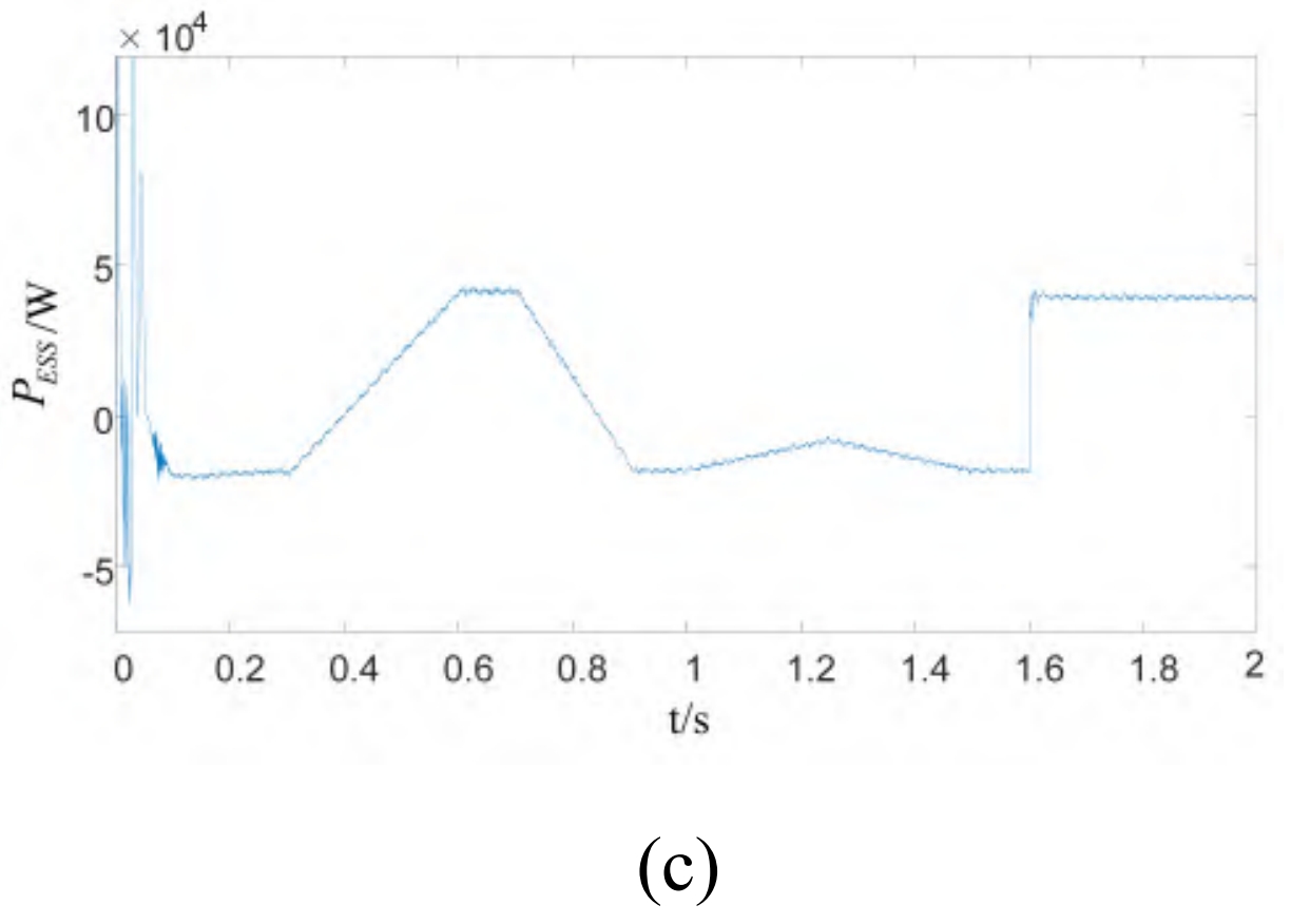
From the phase between the AC bus voltage and current, it can be seen that ADB-SSMC has a significant effect on reactive power control. When increasing the load, the three-phase current oscillates within 0.02 seconds, and due to the balanced power difference between the photovoltaic power supply and the load when ESS is connected, the bus current and frequency quickly enter a steady state. The AC bus voltage and current curve, the bus current curve at the time of load increase, and the active power emitted by ESS are shown in Figures 5 (a), 5 (b), and 5 (c), respectively.
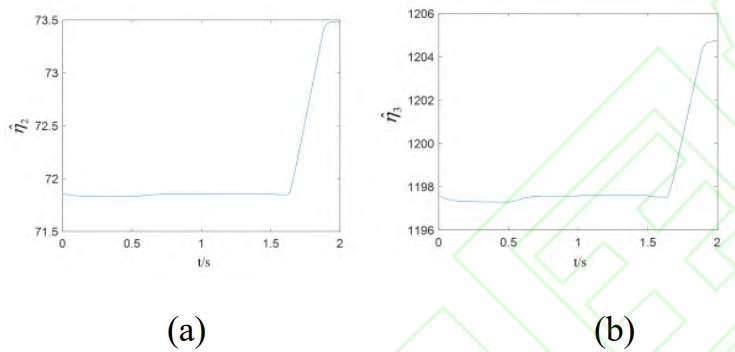
The estimation results of the impedance filter parameters are stable near their true values, and when the parameters perturb from 1.62 seconds to 1.92 seconds, the controller can track the parameter changes in real time and accurately estimate them, which enhances the adaptive and anti-interference performance of the current loop control. Compared with the method of offsetting parameter perturbations by increasing the sliding mode switching gain, the controller designed in this paper can reduce chattering and enhance system stability. The adaptive parameter estimation curve is shown in Figure 6.
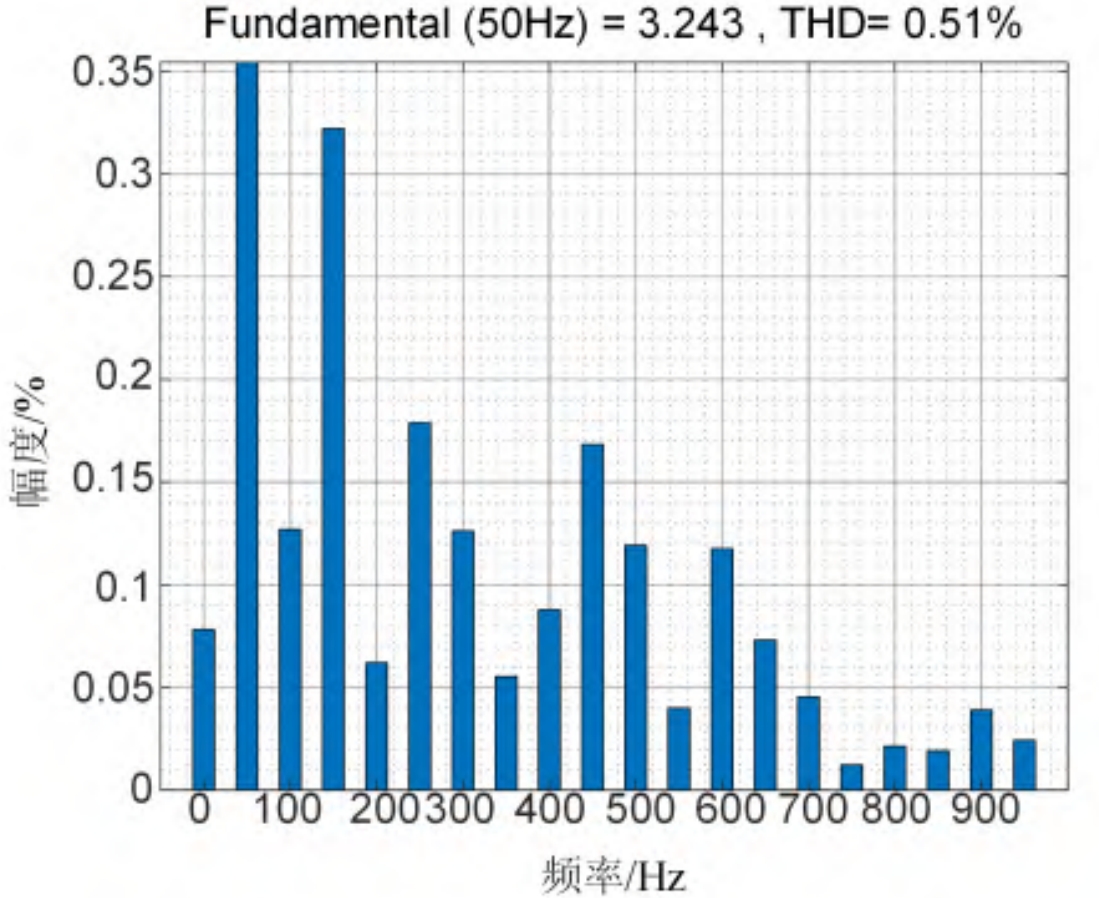
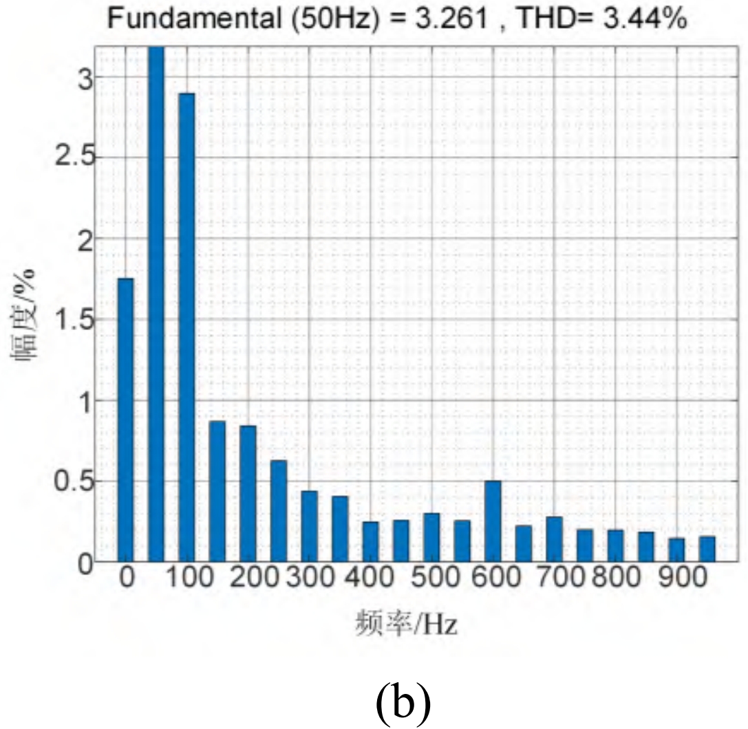
The stability of the output power of the master-slave optical storage system mainly depends on the output current. According to the comparison results of the total harmonic distortion (THD) of AC bus current between ADB-SSMC and ADB-TSMC at the same time, it can be seen that the ADB-SSMC optical storage power generation system has smaller output current ripple, stable power, and meets the requirements of power quality. The bus current THD is shown in Figure 7.
The comparison of specific parameters for DC side voltage tracking performance and busbar current distortion rate under different controllers is shown in Table 1.
5. Conclusion
The main focus of this study is on the power control problem of master-slave islanded solar storage power generation systems, taking into account the impact of intermittent photovoltaic power generation and system noise in practical situations. For solar inverters carrying energy conversion, a disturbance resistant backstepping super spiral sliding mode control strategy with high-order sliding mode differentiator is designed, which can adaptively estimate filtering parameters. According to the Lyapunov theorem, the global asymptotic stability of disturbance estimation and parameter estimation has been proven. The simulation results show that the controller achieves fast tracking of photovoltaic power changes, has the ability to resist load disturbances, has low current harmonic distortion rate, and has precise adaptive ability to filter impedance parameter perturbations. Compared with the terminal sliding mode controller, the control strategy designed in this paper has better transient performance and significant chattering suppression effect.