
As a highly flexible lithium-ion battery energy storage device, the special energy storage shelter can provide stable power supply for outdoor military training, emergency support, scientific exploration, communication maintenance, and other occasions. However, in high-altitude and cold environments, there is no external insulation heating energy supply, and the energy storage battery system is affected by the low temperature environment, resulting in long cold start times and weakened power supply performance, leading to a serious decline in emergency support capabilities. Therefore, designing an efficient and fast cold start scheme and preheating system for special energy storage compartments is of great significance.
In low-temperature environments, the peak power and available power of lithium-ion batteries significantly decrease. S. Herreyre et al. introduced ethyl acetate and methyl butyrate to solve the problem of poor conductivity of electrolyte solutions, ensuring the low-temperature performance of lithium-ion batteries. Research has shown that the main reason for the performance degradation of lithium-ion batteries in low-temperature environments is weakened electrode diffusion, and the possibility of electrode surface performance deterioration is ruled out. Ruan Haijun used sensitivity analysis method to determine the highly sensitive parameters of the electrochemical model. Through quantitative analysis of battery charging and discharging conditions with different model parameters, it was ultimately determined that the main factor causing the low-temperature usable capacity attenuation of lithium-ion batteries was the lower solid phase diffusion coefficient. The above research indicates that in order to improve the power supply performance of lithium battery systems in low-temperature environments, preheating of the battery system is necessary to ensure that the battery system operates within an appropriate temperature range.
At present, there is relatively little research on the preheating system of energy storage compartments, and it is generally based on the preheating technology of vehicle power batteries, mainly external preheating schemes. The external heating methods are divided into air preheating, liquid preheating, and solid preheating according to the different preheating media. The advantage of air preheating is that its structure is simple and easy to implement, but it can cause temperature non-uniformity between individual batteries. At the same time, in low-temperature environments, air preheating will have significant convective heat transfer with the outside world, resulting in lower energy efficiency. Liquid preheating uses flowing media such as water, propylene glycol, and fluoride solution to directly or indirectly heat the battery, resulting in a fast and efficient preheating effect. Wang Facheng [3] designed an air self heating device for power battery packs, and compared the heating performance of the device in blowing mode, suction mode, and mixed blowing and suction mode. The results showed that the suction heating mode can achieve large temperature difference heat transfer, the highest heat transfer efficiency, and the best heating effect. Li Xiaojie [22] studied the heating performance of battery systems using liquid heat and heating film heating methods at low temperatures. The results showed that the charging capacity and energy of battery systems using different heating methods were similar, but the temperature rise rate using liquid heat coupled heating film heating method was approximately equal to the sum of the temperature rise rates of liquid heat and heating film heating methods. Lei conducted low-temperature charging and discharging characteristics experiments on 35 Ah high-power lithium-ion batteries and proposed a method of wide wire metal film heating batteries. Research has shown that using wide wire metal film heating can significantly improve the performance of battery packs, and the heated battery pack can achieve high current charging and discharging, with a power of nearly 80%. Although the above preheating methods significantly improve the performance of the battery system, the preheating process is long, usually taking 20 minutes, and there is a long energy supply window, which cannot meet the rapid energy supply needs in special application scenarios. At the same time, special energy storage shelters are generally used as independent power supply facilities, and there is also a problem of no external preheating energy supply.
In response to the above issues, this article proposes a combination ratio scheme of low-temperature batteries and energy storage batteries, and designs a fast and efficient preheating system that can effectively shorten the preheating startup time of special energy storage compartments, reduce preheating energy consumption, expand the range of usage scenarios of special energy storage compartments, and improve the emergency support power system and military civilian mobile power supply support capabilities.
1.Design of low-temperature self preheating strategy for special energy storage compartments
1.1 Selection and performance analysis of lithium-ion batteries
Among the types of lithium-ion energy storage batteries, ternary lithium batteries have high energy density, but their low-temperature performance is poor. Lithium titanate batteries have excellent low-temperature performance, but their energy density is low [8]. In order to meet the requirements of high energy density and high and low temperature performance in the special energy storage shelter, the shelter battery system adopts a combination of ternary lithium battery energy storage battery pack and lithium titanate low-temperature heating auxiliary battery pack.
1.1.1 Ternary lithium battery
The discharge experimental characteristic curve of a certain type of ternary lithium battery is shown in Figure 1.
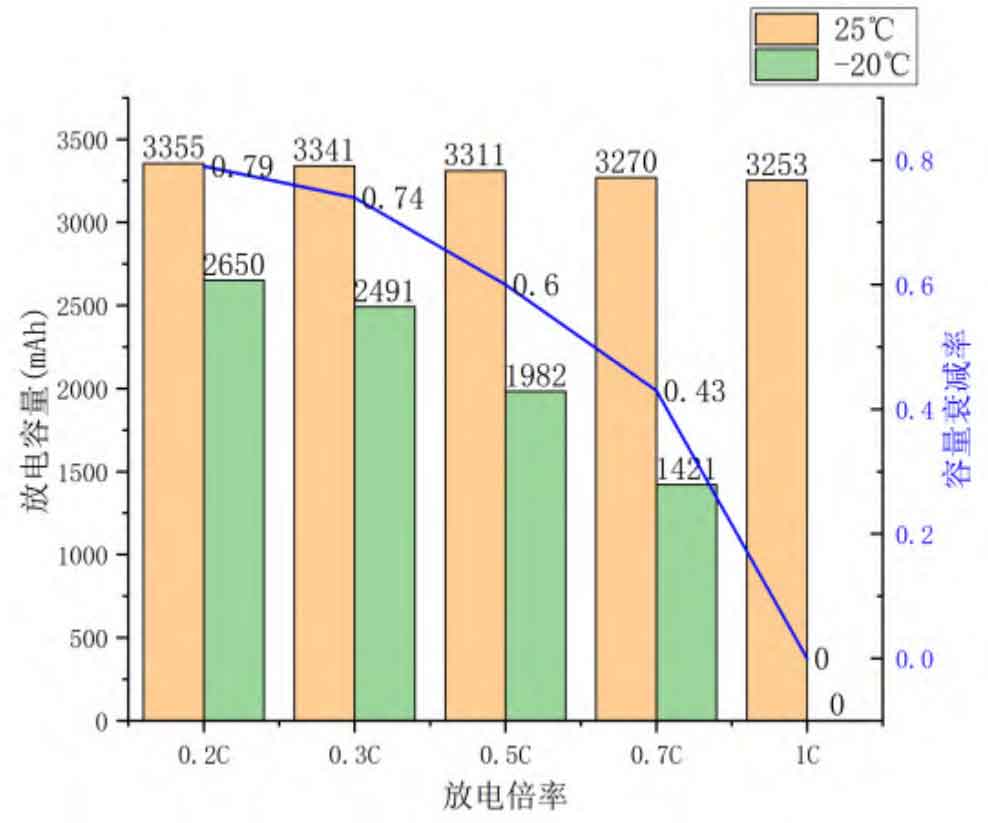
The experimental results show that at an ambient temperature of 25 ℃, there is little change in discharge capacity at different rates. The retention rates of ternary lithium batteries at discharge rates of 0.2 C, 0.3 C, 0.5 C, 0.7 C, and 1 C are 100.1%, 99.8%, 98%, 97.6%, and 97%, respectively. In a low temperature environment of -20 ℃, when a ternary lithium battery is discharged at a rate of 1 C, the terminal voltage drops to the protection voltage at the moment of discharge, making it unable to discharge its electricity.
At the same discharge rate and different environmental temperatures, the capacity retention rates are 79%, 74%, 60%, 43%, and 0%, respectively. The energy density of ternary lithium batteries is high, but their low-temperature performance is poor.
1.1.2 Lithium titanate batteries
The discharge experimental characteristic curve of a certain type of lithium titanate battery is shown in Figure 2.
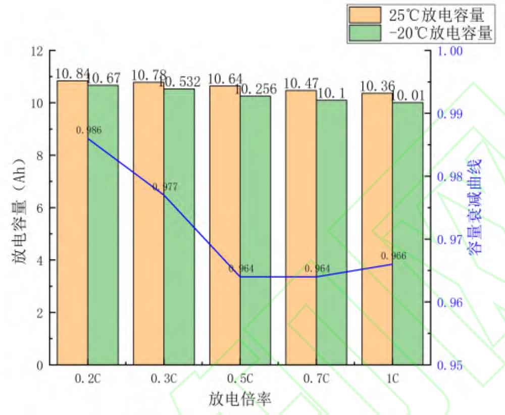
The experimental results show that the impact of different discharge rates on the discharge capacity of lithium titanate batteries is relatively small at an ambient temperature of 25 ℃. At the same time, due to the resistance of its positive and negative electrode materials to low temperatures, the discharge capacity of lithium titanate batteries remains above 90% at an ambient temperature of -20 ℃. Lithium titanate batteries have good low-temperature performance, but their energy density is low.
1.2 Design of battery system self preheating and energy supply strategy
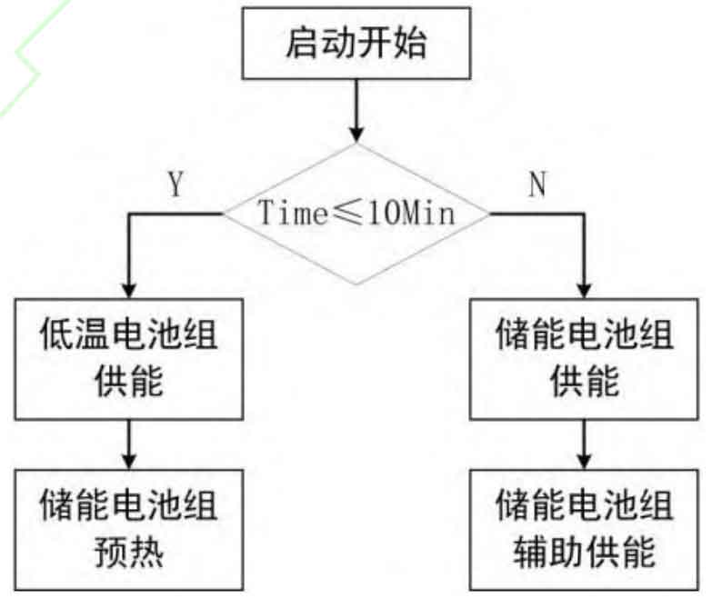
In order to meet the continuous power supply and battery performance reliability, combined with the actual energy supply needs under emergency support conditions, the preheating time of the energy storage battery pack is set to 10 minutes. In the first 10 minutes, due to the inability of the energy storage battery pack to discharge at low temperatures, it is in the energy supply window period. At this time, it is powered by a lithium titanate battery pack with good low-temperature performance. At the same time, the lithium titanate battery pack preheats the energy storage battery pack to normal operating temperature within 10 minutes; After 10 minutes, the energy storage battery pack is preheated to reach the target temperature, and the energy of the energy storage battery pack is controlled to be imported into the output terminal for power supply, continuously supplying external energy. The lithium titanate battery pack will assist in adapting to the functional changes on the load side, as shown in Figure 3.
1.3 Analysis of preheating target temperature for energy storage battery pack
According to the operating conditions of the energy storage shelter, cyclic charging and discharging comparative tests were designed at ambient temperatures of 25 ℃, 5 ℃, 0 ℃, and -20 ℃. The experimental results are as follows:
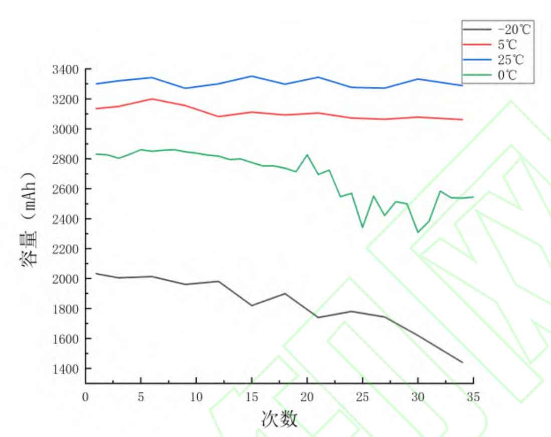
According to Figure 4, during 30 tests at 25 ℃, the discharge capacity of the 18650B ternary lithium battery fluctuated slightly, but remained near the calibrated capacity without any signs of decay. In 30 tests at 5 ℃, its discharge capacity slightly decreased, with a discharge capacity of 3098 mAh for the 30th test, which decreased by 37 mAh compared to the first test, and the capacity decreased by 1.2%. In 30 tests at -20 ℃, the discharge capacity of the battery showed a slight and significant decrease. The discharge capacity of the 30th test was 1640 mAh, which decreased by 382 Ah compared to the first test, and the capacity decreased by 18.7%- At 20 ℃, the battery capacity decayed from 2042 mAh to 1640 mAh and was only used 30 times. However, the service life of this batch of batteries is about 600-1000 times, indicating that charging and discharging at low temperatures have a significant impact on the cycling life of the batteries. When the temperature is 0 ℃, the capacity curve of the 18650B ternary lithium battery shows a slow overall decrease trend during the first 20 tests. However, the subsequent discharge capacity showed fluctuating changes, mainly due to the actual error of the incubator being around 1 ℃. When the test temperature was set to 0 ℃, the actual temperature of its inner chamber varied back and forth between -1 ℃ and 1 ℃. However, the batteries of this batch were more sensitive to temperature changes around 0 ℃, resulting in the above situation.
By comparing the experimental results at different temperatures, setting the preheating target temperature of the ternary lithium battery energy storage group to 5 ℃ can ensure the external energy supply demand of the energy storage shelter.
2.Capacity configuration and topology design of the energy storage shelter battery system
2.1 Capacity configuration and topology design of energy storage battery packs
When studying capacity configuration, the performance requirements of the energy storage shelter should be determined first. The performance requirements of the energy storage shelter studied in this article are shown in Table 1:
| Design parameters | Value |
| Storage capacity (kWh) | ≥ 300 |
| Output voltage (V) | 220 |
| Maximum energy density (Wh/kg) | 140 |
| Discharge rate | 1C |
| Charging rate | 1-2C |
| Operating temperature (℃) | -20-40 |
Due to the continuous output requirement of 200 kWh on the load side, it was found from the battery cell parameter table that this type of ternary lithium battery belongs to a representative typical battery cell, with a maximum continuous discharge rate of 1 C. The minimum configuration value of the theoretical battery system total capacity is:
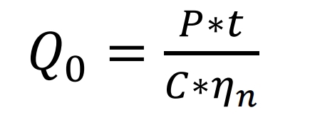
P is the continuous output power of 200 kW on the load side, t is the output duration, C is the discharge rate, and 𝜂𝑛 is the inverter efficiency, taken as 0.95. The daily capacity of ternary lithium batteries is maintained at around 90% -95% of room temperature 25 ℃ in the 5 ℃ range. Due to the strict requirements of usage scenarios, the minimum limit of 90% is taken. At the same time, redundant design is carried out for the ternary lithium battery energy storage system, and the corrected capacity Q1 is:
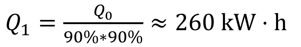
At around 5 ℃, a pure inverter input capacity of 260 kWh is required to meet 200 kW × 1 hour inverter output demand. At the same time, to meet the needs of emergency scenarios such as outdoor, disaster relief, and emergency power supply, the voltage of the detachable use unit of the energy storage shelter must meet the voltage requirements of household appliances, which is greater than or equal to 220 V. The storage capacity formula of the battery system is:

In the formula, u0 is the voltage value of the 18650B ternary lithium battery, taken as 3.7 V, A0 is the capacity of the 18650B ternary lithium battery, taken as 3.4 Ah, n is the number of series batteries, and m is the number of parallel batteries. The final determination of the energy storage shelter battery system is shown in Table 2:
| Voltage (V) | Capacity (Ah) | Storage capacity (kWh) | |
| Cell | 3.7 | 3.4 | 0.01258 |
| Module (1s48p) | 3.7 | 163.2 | 0.61 |
| Standard Package (16s48p) | 59.2 | 163.4 | 9.67 |
| Battery cluster (64s48p) | 236.8 | 163.4 | 38.69 |
| Energy storage system (64s336p) | 236.8 | 1143.8 | 270.852 |
2.2 Auxiliary battery pack capacity configuration and topology design
There are two main functional requirements for the overall external output of lithium titanate batteries. The first part is that in the first 10 minutes, the energy storage battery pack cannot discharge due to low temperature, leaving an energy supply window period. Lithium titanate batteries need to continuously output power on the load side of the energy storage compartment; The second part is the provision of preheating energy for ternary lithium battery energy storage systems using lithium titanate batteries within the first 10 minutes.
The minimum configuration value for the total capacity of a theoretical lithium titanate battery system is:
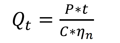
P is the load side holding output power of 200 kW, t is the output duration (10 minutes), C is the discharge rate, and 𝜂𝑛 is the inverter efficiency, taken as 0.95. Lithium titanate batteries are maintained in the range of -20 ℃, with daily usage of approximately 96.4% -98.6% of room temperature 25 ℃. Due to the strict requirements of usage scenarios, a lower limit value of 96.4% is taken. At the same time, redundant design is carried out for the ternary lithium battery energy storage system, and the corrected capacity Q1 is:
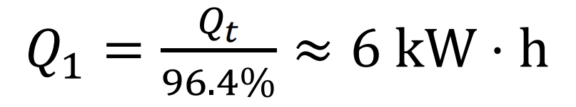
-At around 20 ℃, a pure inverter input capacity of 6 kWh is required to meet the inverter output demand of 200 kW within ten minutes. According to the instructions and experimental demonstration of the lithium titanate manufacturer, the lithium titanate battery can maintain a maximum external continuous discharge of 120 W for more than 10 minutes. The experimental test is shown in Figure 5:
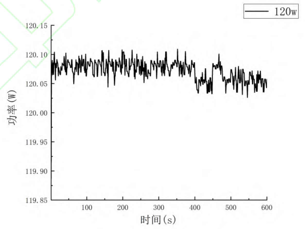
In terms of power demand, the number of lithium titanate batteries is:
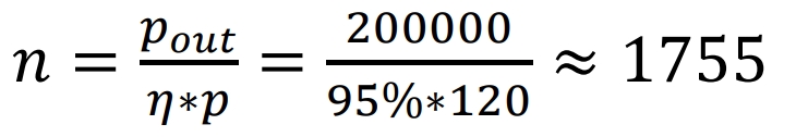
According to the preheating energy demand:
In the formula, Qw is the total preheating energy, Cb is the specific heat capacity of the 18650B lithium battery, mb is the total mass of the 18650B lithium battery, Tb is the preheating termination temperature, E is the loss energy of convective heat transfer, C1 is the specific heat capacity of other materials, m1 is the total mass of other materials, and T1 is the preheating termination temperature of other materials. The final solution obtained an overall preheating power of 2400 W for the battery standard package.
In summary, a total of 2335 lithium titanate batteries are required to meet the energy supply needs of the load side and preheating side of the energy storage compartment for the first 10 minutes.
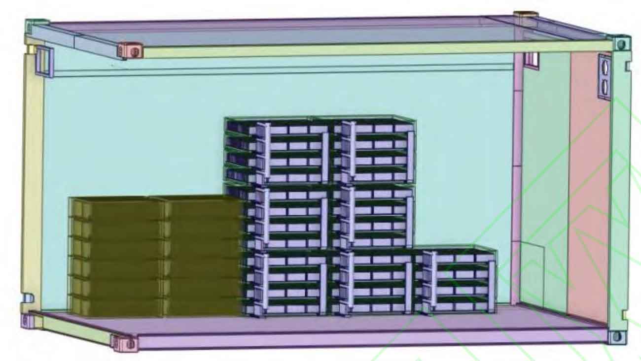
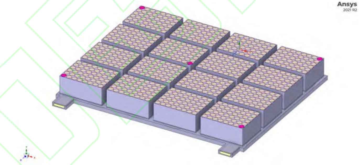
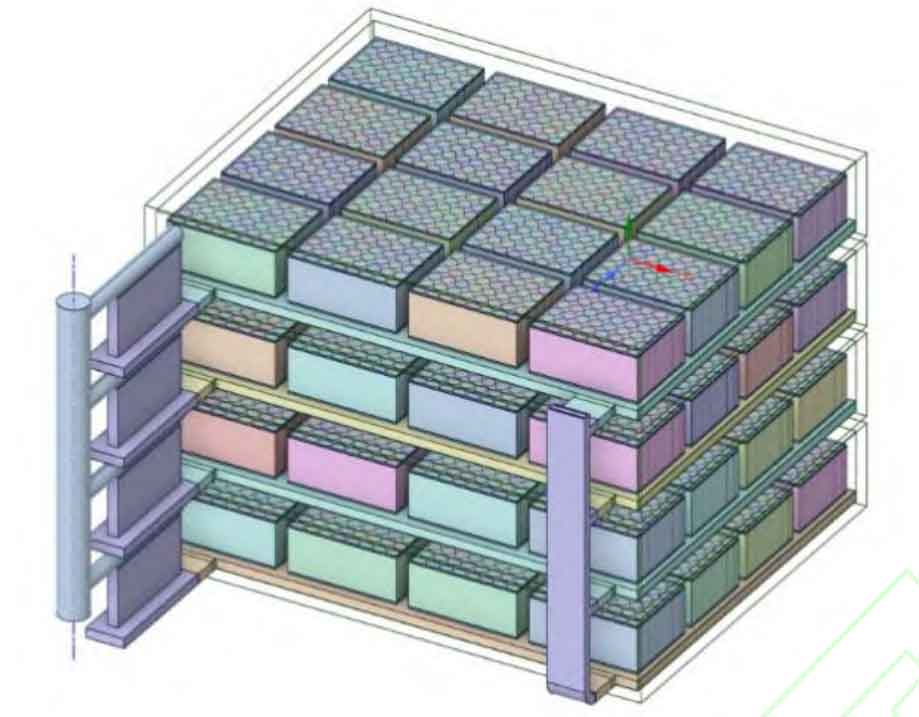
The three-dimensional structure of the final overall energy storage compartment is shown in Figure 6. The gray area on the right is the energy storage battery pack, and the yellow area on the left is the auxiliary battery pack.
3.Simulation of preheating system scheme design and analysis of influencing factors
3.1 Design and simulation of preheating scheme for battery standard package
Due to the heat transfer between the battery module and the liquid heat plate and the convection on the surface of the standard package shell being the main heat transfer behavior, the heat transfer behavior between other components and the battery or cold plate can be ignored. Therefore, this article designs a layout plan for a horizontal double serpentine flow channel liquid cooled pipeline, as shown in Figure 8.
Simulate the preheating effect of the liquid hot plate arranged in this channel using Fluent. During the simulation process, it is necessary to set the boundary conditions for the simulation: the surface of the box is set to convective heat dissipation, the convective heat dissipation coefficient is 5 W/(m2 ∙ K), and the convective temperature is -20 ℃; The inlet of the cold plate is a velocity type inlet, with speeds set at 0.2 m/s, 0.5 m/s, and 1 m/s. The outlet of the cold plate is a pressure type outlet; The ambient temperature is -20 ℃. The simulation results are shown in Figures 9-11.
The above simulation results indicate that for the battery standard package preheated with a horizontal double serpentine arrangement, the highest temperature appears at the bottom of the single cell near the inlet end, while the lowest temperature appears at the top of the single cell near the outlet end. The temperature uniformity of the overall battery changes with the increase of flow rate.
3.2 Orthogonal experimental analysis
Due to many factors affecting the preheating temperature and temperature uniformity of batteries. Therefore, this article will use orthogonal optimization experiments to analyze the influence of various factors on preheating effect and energy consumption based on the layout scheme of a horizontal serpentine dual channel hydrothermal plate. In engineering practice, the temperature of liquids is a continuously changing process, making it difficult to conduct qualitative analysis. According to relevant research papers, the temperature of the liquid has a significant impact on the highest and lowest temperatures of the cell, while it has a smaller impact on the pressure drop and temperature difference. Therefore, when analyzing the sensitivity of preheating effect to three factors (liquid temperature, liquid flow rate, and pipeline width), it is necessary to select a certain factor for variable control. When designing relevant orthogonal experiments, only the cell temperature difference and pressure drop are used as evaluation indicators. Select the orthogonal table of L16 (2413) and design the orthogonal table header as shown in Table 3.
| Horizontal | Medium temperature T (℃) | Inlet flow velocity G (m/s) | Pipe diameter width H (mm) |
| 1 | 7 | 0.5 | 20 |
| 2 | 8 | 0.6 | 25 |
| 3 | 9 | 0.8 | 30 |
| 4 | 10 | 1 | — |
According to the orthogonal factor level table in Table 3, as it is not a standard orthogonal table, it needs to be modified by combining the combination method and the quasi horizontal method. A total of sixteen simulation calculation models corresponding to experiments were established, and the lowest temperature and fluid pressure drop between batteries were selected as evaluation indicators. The simulation analysis was conducted using Fluent software, and the simulation experimental results are shown in Table 4.
| Experiment number | T (℃) | G (mm) | H (mm) | Δ T (℃) | Press (Pa) |
| 1 | 7 | 0.5 | 20 | 8.69 | 6280 |
| 2 | 7 | 0.6 | 25 | 7.051 | 3590 |
| 3 | 7 | 0.8 | 30 | 6.518 | 7350 |
| 4 | 7 | 1 | 20 | 7.48 | 19323 |
| 5 | 8 | 0.5 | 25 | 7.836 | 4000 |
| 6 | 8 | 0.6 | 20 | 8.58 | 8450 |
| 7 | 8 | 0.8 | 25 | 6.901 | 8620 |
| 8 | 8 | 1 | 30 | 6.549 | 11000 |
| 9 | 9 | 0.5 | 30 | 8.188 | 3500 |
| 10 | 9 | 0.6 | 30 | 8.08 | 4740 |
| 11 | 9 | 0.8 | 20 | 8.329 | 13442 |
| 12 | 9 | 1 | 25 | 6.55 | 12400 |
| 13 | 10 | 0.5 | 25 | 8.32 | 4226 |
| 14 | 10 | 0.6 | 30 | 7.63 | 4740 |
| 15 | 10 | 0.8 | 25 | 7.385 | 8620 |
| 16 | 10 | 1 | 20 | 8.26 | 19323 |
| 17 | 10 | 1 | 30 | 7.09 | 11047 |
By conducting an analysis of variance on the above results, the following conclusions can be drawn: with pressure as the object, flow rate as a highly significant factor, pipe diameter as a significant factor, and temperature as a non significant factor; Target the lowest temperature, with liquid temperature as a significant factor and the rest as insignificant factors; For the maximum temperature difference, these three factors are not significant within the range. Although liquid temperature is a significant factor in the minimum temperature, analyzing the results of sixteen orthogonal experiments shows that increasing the inlet liquid temperature cannot completely solve the problem of low minimum temperature of the battery cell.
Based on comprehensive balance considerations, the schemes of 0.5 m/s and 30 mm pipe diameters are selected.
4.Simulation and optimization of preheating system for closed-loop liquid-thermal coupling heating film of battery standard package
In practical engineering applications in low-temperature environments, the liquid temperature should be consistent with the ambient temperature. The preheating process actually involves preheating the components to heat the liquid, and the water pump starts to rotate. The preheating liquid is then preheated to the battery through a hydrothermal plate. At the same time, increasing the inlet liquid temperature cannot completely solve the problem of low minimum temperature of the battery cell.
To address the above issues, this section designs a closed-loop liquid thermal coupling heating film preheating system. The system includes three parts: liquid closed-loop preheating using UDF language, preheating of liquid by heating components, and preheating of battery positive electrode by heating film. The implementation process of closed-loop preheating is to first locate the ID of the outlet and obtain the area and temperature values of each node at the outlet. Then calculate the sum of the area of all nodes and the sum of the area and temperature multiplication values of all nodes to obtain the arithmetic mean of the nozzle temperature. Finally, based on the analysis time step, assign the arithmetic mean of the outlet temperature from the previous calculation step to the inlet of the next calculation step.
The water temperature at the inlet should be the arithmetic mean of the outlet temperature, as follows:

In the formula, Tinlet is the inlet liquid temperature, Ti is the temperature value of each node, ci is the area of each node, where i=1, 2,…, n.
This article places PTC material on the water inlet side for preheating the liquid in the water inlet. At the same time, cover the positive electrode of the energy storage battery with a layer of polyimide heating film with a thickness of 0.25 mm.
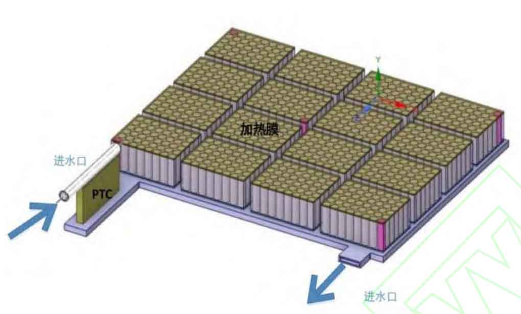
Finally, the three-dimensional structure of the standard package preheating system based on closed-loop liquid-thermal coupling heating film is shown in Figure 12 (the upper insulation layer of the box and battery module is treated with transparency):
4.1 Simulation of PTC under constant power operating state
Simulate the standard package using Fluent software, treating PTC as a volumetric heat source with a working state of 2340 W constant power. Set a thin shell for heat transfer on the upper insulation layer of the battery module, with a thickness of 0.25 mm and a power of 2.5 W/cm2. Set the ambient temperature to -20 ℃, load the UDF program, and set the simulation time to 600 seconds.
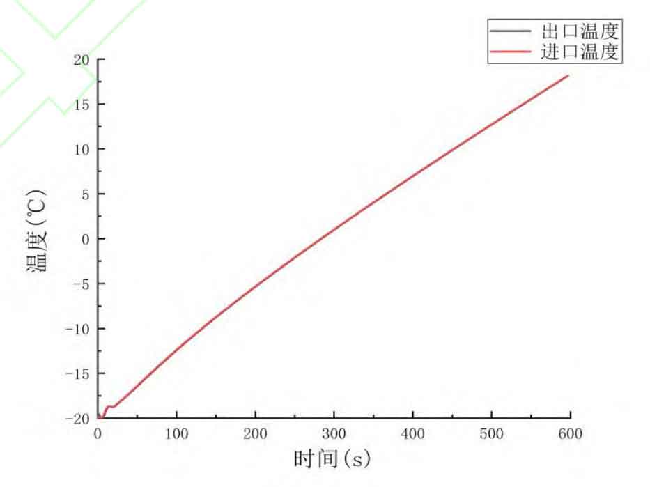
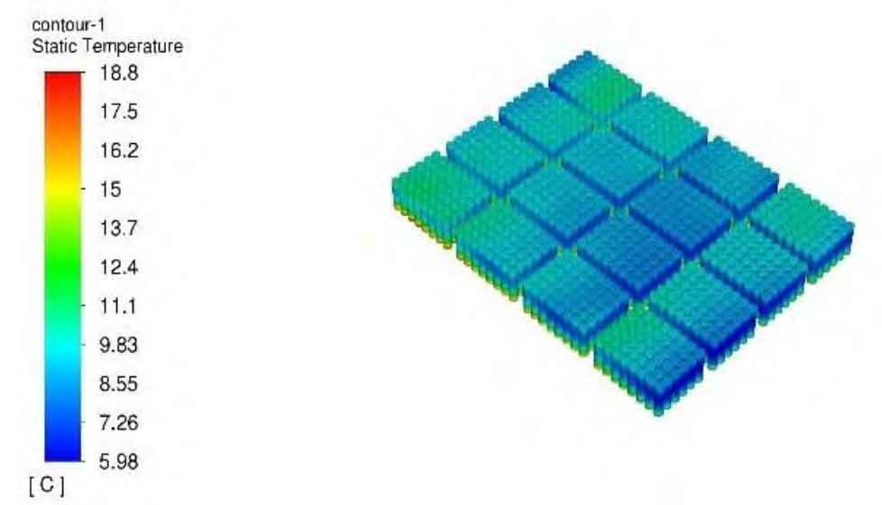
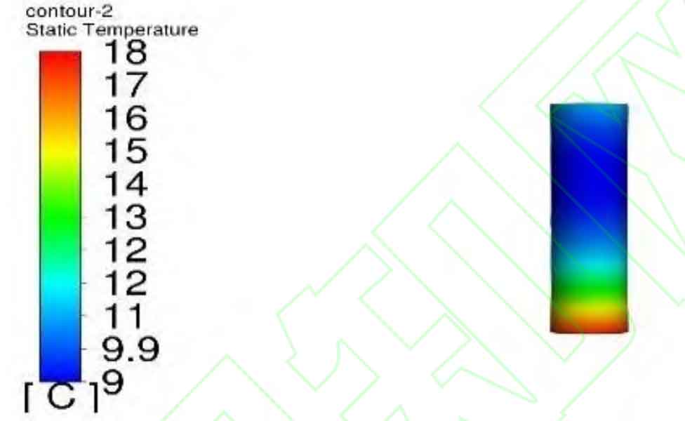
From Figure 13, it can be seen that the time temperature curve of the outlet and the time temperature curve of the outlet are completely consistent, indicating that the arithmetic mean of the surface grid temperature of the outlet liquid in UDF is successfully assigned to the next step of the inlet temperature. From Figure 14, it can be seen that after PTC constant power preheating for 600 seconds, the minimum temperature of the overall battery is 5.98 ℃, which meets the preheating requirements. However, due to the constant power operation of PTC and the continuous heating of the liquid, the temperature of the liquid near the inlet continues to rise, resulting in a higher negative electrode temperature of the battery near the inlet area, reaching a maximum temperature of 18.8 ℃. The liquid undergoes convective heat transfer inside the liquid hot plate, resulting in a decrease in liquid temperature at the outlet. Therefore, the average temperature of the battery on the outlet side is the lowest, ultimately resulting in a large temperature difference between the negative electrodes of the entire battery standard pack, with the highest temperature difference between the batteries reaching 12.82 ℃. As shown in Figure 15, the temperature difference between the positive and negative electrodes of the single cell battery reaches 9 ℃. A large temperature difference not only causes inconsistent performance of the battery, but also causes high energy loss. This preheating result can meet the system requirements, but it results in poor temperature uniformity of the battery. Therefore, it is necessary to adjust the PTC working state.
4.2 Simulation of PTC under constant power to constant temperature operating state
This section will set the PTC ceramic heater to operate at constant power, continuously heating the liquid, and monitoring the liquid temperature at the inlet of the liquid heating plate. When the temperature of the liquid entering the hydrothermal plate is detected to be 10 ℃, the PTC heater switches to a constant temperature operating state, maintaining the liquid temperature at the inlet of the hydrothermal plate at 10 ℃. The total preheating time is still 10 minutes. Set the ambient temperature to -20 ℃ and simulate the battery standard package using Fluent.
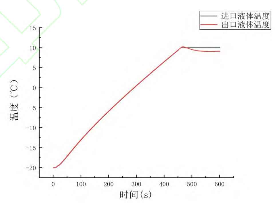
According to the simulation results, at 0 s-450 s, the PTC ceramic heater is in a constant power range, and the liquid temperature rises from -20 ℃ to 10 ℃. Under the action of a closed-loop cold chain, the liquid temperature at the inlet and outlet of PTC almost completely coincide. From 451 seconds to 600 seconds, PTC is in a constant temperature working state, ensuring that the temperature of the imported liquid is maintained at 10 ℃. After preheating the PTC at a constant temperature for 150 seconds, the minimum temperature of the battery reaches 5.4 ℃, and the highest temperature of the battery occurs in the positive and negative electrode areas closest to the inlet of the hydrothermal plate, with a maximum temperature of 9.9 ℃. The maximum temperature difference between batteries is only 4.5 ℃. The PTC constant power to constant temperature preheating scheme not only meets the overall battery preheating needs, but also controls the temperature difference between batteries within 5 ℃, ensuring consistency in battery temperature. At the same time, the maximum temperature of the battery should be controlled within 10 ℃ to reduce energy loss in the preheating system.
4.3 Simulation analysis of battery cluster preheating
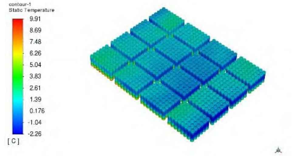
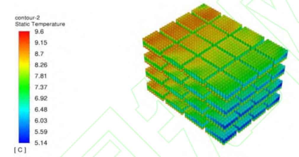
The geometric model of the energy storage battery system in the energy storage shelter is huge and the structure is complex. If the entire energy storage battery system is subjected to thermal simulation, there is a problem of high computational complexity and long solving time. The energy storage battery system is composed of 7 battery clusters in parallel, and the rated voltage of the battery clusters is 220 V, meeting the voltage usage requirements. Therefore, battery clusters have typical representativeness, so this article will only conduct thermal simulation analysis of battery clusters.
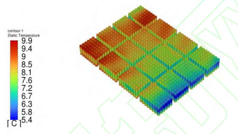
Based on the PTC constant power to constant temperature preheating strategy mentioned in the previous section, the following temperature cloud map is obtained after preheating for 10 minutes: According to the simulation results in Figure 19, the minimum temperature of the entire four layer single cell battery is 5.14 ℃, the maximum temperature is 9.6 ℃, and the overall maximum temperature difference is controlled at 4.46 ℃. The overall temperature distribution of the battery cluster decreases from the inlet side to the outlet side. The battery pack with poor preheating effect is the bottom layer, which is caused by the flow direction design of the water inlet main pipeline. Therefore, the lowest temperature appears in the middle section of the battery pack near the outlet side.
5. Conclusion
This article focuses on the issues of battery performance degradation and difficulty in uninterrupted power supply to loads in special energy storage compartments under low temperature environments. The topology structure, capacity configuration, and preheating strategy of the energy storage compartment are studied. The main conclusions are as follows:
(1) Propose a combination form of ternary lithium battery energy storage battery pack and lithium titanate low-temperature heating auxiliary battery pack, and design preheating and heating strategies for them, which can effectively solve the problem of energy supply window period during the preheating process of special energy storage compartments.
(2) Through low-temperature performance experiments on batteries, it can be seen that in low-temperature environments, the capacity of energy storage batteries deteriorates severely, with a 1 C discharge capacity retention rate of 0%. The performance of discharge assisted batteries is less affected by low temperature, with a capacity retention rate of over 90%.
(3) A closed-loop liquid-thermal coupled heating film preheating system was designed for the proposed new energy storage architecture, and its preheating effect was verified through Fluent simulation. The results showed that the preheating system can preheat the energy storage battery from -20 ℃ to above 5 ℃ within 10 minutes, and the overall maximum temperature difference is controlled at 4.46 ℃.