
1. Introduction
The oilfield industry is constantly evolving, and the demand for more efficient and environmentally friendly equipment is increasing. Workover rigs play a crucial role in maintaining and enhancing the productivity of oil wells. Traditional workover rigs powered by diesel engines have several drawbacks, such as high energy consumption, large noise emissions, and low efficiency, along with significant pollution gas production during operation. In contrast, electric workover rigs offer advantages like clean energy utilization, energy savings, low noise, and high efficiency with no pollution emissions. However, different types of electric workover rigs have faced challenges in practical applications. For example, when connected to a low-voltage grid, the on-site construction is relatively easy and safe, but due to limitations of the wellsite transformer (usually 75 kV·A/400 V), the grid power supply is insufficient, resulting in slow hoisting and lowering speeds of the workover rig and poor stuck-pipe releasing capabilities, failing to meet the working capabilities and operational efficiency of conventional workover rigs. When connected to a high-voltage grid (10 kV/6 kV), although not restricted by the wellsite power distribution, it requires a separate high-voltage mobile substation, increasing equipment investment and installation and removal workload. Additionally, each operation must be approved by the oilfield power supply department and connected and removed by professional electricians, leading to long waiting times and high safety risks.
Lithium iron phosphate batteries, with their unique properties, have emerged as a promising solution for energy storage in workover rigs. These batteries have the potential to address the power supply issues faced by electric workover rigs and offer a more sustainable and efficient option for oilfield operations.
2. Overall Design Requirements of the Lithium Iron Phosphate Battery System for Workover Rigs
The entire battery energy storage system consists of several key components, including PACK battery modules, BMS (Battery Management System), a charge-discharge management system, and a thermal management system.
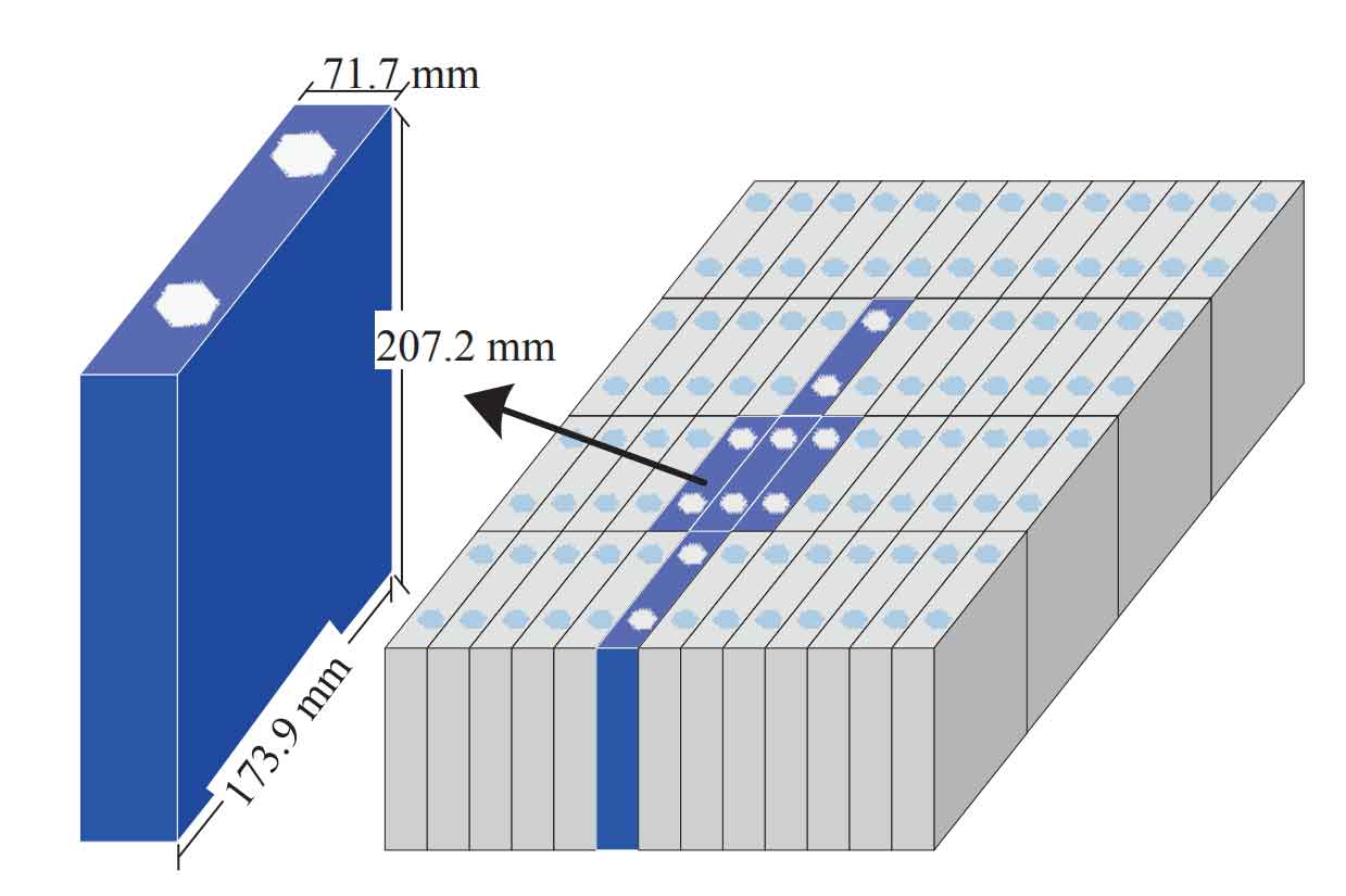
The PACK battery modules output high-voltage direct current, which is then inverted to 380 V alternating current by an inverter to drive the electric winch of the workover rig and wellsite auxiliary equipment. The system is designed to meet the requirements of small workover operations with a continuous discharge current of 300 A and a peak current of 450 A (for 20 s). The lithium iron battery box is equipped with a battery rack, and the PACK battery modules are installed in a stacked manner at the specified positions on the rack. The lithium iron battery cells are required to be made of materials with high energy density, high working voltage, long cycle life, and good safety performance. The thermal management system controls the internal temperature to meet the usage requirements in both hot and cold regions.
3. Design of the Energy Storage System
3.1 Workover Rig Operating Conditions
The small workover operation process mainly involves pulling out and lowering the tubing and sucker rods in the well. This process can be divided into “two stages and three steps” and is a typical intermittent operation. The “two stages” refer to pulling out and lowering. The pulling-out operation is the process of lifting the tubing (or sucker rod) from the oil well to the ground, while the lowering operation is the process of lowering the pulled-out tubing (or sucker rod) back into the well after the small workover is completed. The “three steps” include lifting, making/breaking connections, and lowering, with each of these three processes taking an average of about 20 s. During the operation of the workover rig, pulling out each tubing (or sucker rod) is an independent working process, and the entire working stage is completed through continuous cycles. In the pulling-out stage, as the tubing (or sucker rod) is continuously pulled out, the output power of the workover rig decreases continuously, presenting a periodically decreasing power output process. The opposite is true for the lowering stage. Ignoring the decrease and increase in power output during the overall operation process, the simplified power output curve.
Taking advantage of the intermittent power demand characteristics of workover operations, the energy storage device only needs to release electricity quickly for 1/3 of the time, and it can be charged throughout the entire operation process. The energy storage device and the wellsite grid can supply power to the workover rig simultaneously to complete the pulling out of one tubing (or sucker rod). By utilizing the periodic characteristics and continuous cycling, the normal operation of the electric workover rig can be achieved with limited grid resources.
3.2 Composition of the Energy Storage System and Battery Selection
The energy storage system mainly consists of an energy storage battery, BMS, a charge-discharge management system, and a thermal management system. The battery, as an energy storage device, needs to meet the usage requirements. However, the energy density and charge-discharge characteristics of the energy storage battery will determine the working performance of the electric winch of the workover rig. Therefore, the selection of the energy storage battery is of utmost importance. Currently, there are several types of battery cells widely used in the market, such as lithium iron phosphate, ternary lithium, and lead-carbon batteries (Table 1).
| Battery Type | Lithium Iron Phosphate Battery | Ternary Lithium Battery | Lead – Carbon Battery |
|---|---|---|---|
| Cycle Life (h) | >6000 | 6000 | 3000 – 4000 |
| Energy Density | Acceptable | Higher | Medium |
| Discharge Depth | High | High | Medium |
| Long – term Use Cost | Acceptable | Acceptable | High Residual Value |
| Charge – Discharge Rate | High | High | Low |
| Energy Conversion Rate (%) | 95 | 95 | 90 |
| Operating Environment Temperature (°C) | -20 – 55 | 25 ~ 28 | -20 ~ 55 |
From Table 1, it can be seen that the comprehensive performance of the lithium iron battery is more superior. At the same time, from the discharge curve of the lithium iron battery, it can be observed that its charge-discharge characteristics can better adapt to the requirements of the outdoor operating environment temperature of the workover rig.
3.3 Battery Management System (BMS)
The BMS has several important functions. It intelligently manages and maintains each battery unit to prevent overcharging and over-discharging, thereby extending lithium iron battery life and monitoring the lithium iron battery status. Its specific functions include:
- During lithium iron battery charge-discharge process, it real-time collects the terminal voltage and temperature of each battery in the battery pack, as well as the charge-discharge current and the total voltage of the battery pack, preventing overcharging or over-discharging of the batteries. The battery parameters directly reflect the operating state of the lithium iron battery and provide data support for other functions of lithium iron battery management system. At the same time, it identifies faulty batteries to maintain the reliability and efficiency of the entire battery pack.
- It balances the energy between individual batteries to avoid inconsistencies caused by manufacturing and operation, extending lithium iron battery life and energy utilization rate.
- It calculates the SOC (State Of Charge) to real-time detect the state of charge of lithium iron battery. The SOC is used to represent the remaining battery capacity. The Coulomb integral is used for real-time calculation of the SOC to ensure that lithium iron battery charge remains within a reasonable range, preventing damage to the battery due to overcharging or over-discharging.
- It controls the connection and disconnection of the batteries. It controls the relays of all battery packs to open and close. The fault diagnosis and protection alarm are divided into two levels. The first level is an alarm level, and if exceeded, an alarm is directly issued. The second level is a cut-off level. If exceeded, it indicates a serious fault and the branch switch will be directly cut off.
- It manages data communication and records data. It is responsible for data transmission between several battery modules, between lithium iron battery management system and the charger, and between lithium iron battery management system and the main control system. Among them, the PCS (Power Conversion System), also known as bidirectional energy storage inverter, is a core component for enabling bidirectional power flow between the energy storage system and the grid.
3.4 Battery Charge – Discharge Strategy
The hardware of lithium iron battery charge-discharge system consists of a wellsite transformer, a charger, a DC/DC converter, and an energy storage battery. The management system automatically charges and discharges according to a pre-defined strategy based on the power demand of different operating conditions.
The wellsite alternating current power is provided by a 380 V, 50 kV·A wellsite transformer. After passing through the charger, it is converted into direct current. The output side of the charger is connected to a DC/DC converter (connected to lithium iron battery) and a DC/AC inverter (connected to the load). The direct current output by the charger preferentially supplies power to the load. When the load is operating at low energy consumption and lithium iron battery is not fully charged, the remaining power charges lithium iron battery, and the charger is in a full-load charging state. When the load is operating at low energy consumption and lithium iron battery is fully charged, the charger is controlled not to charge lithium iron battery, and the charger is in a non-full-load charging state. When the load is operating at high energy consumption, the direct current output by the charger cannot meet the load requirements, and the difference between the load requirements and the charger output is provided by the battery discharge.
When lithium iron battery charge is insufficient to provide the difference between the load requirements and the charger output, lithium iron battery stops discharging, and the workover rig stops operating. When the controller determines that the motor is in a reverse power generation state, if the reverse power generation current of the motor is less than the charging current limit of the energy storage battery and the energy storage battery is not fully charged, the current passes through the direct current bus via a DC/DC converter to charge the energy storage battery. If the energy storage battery is fully charged and the direct current bus voltage rises to a threshold, the excess energy is consumed by activating a braking unit with a braking resistor.
3.5 Thermal Management System
The thermal management system has two functions: cooling and heating. It can be set through an upper computer to control the start and stop temperatures of cooling and heating, thereby controlling the environmental temperature of lithium iron battery to ensure that lithium iron battery operates within the optimal charge-discharge interval. The cooling function uses an embedded liquid-cooling integrated machine. Considering the special requirements of temperature control and installation space for energy storage batteries, it adopts an integrated structure and a door-mounted embedded installation method. The condensing side uses a back-blowing method, which is closer to the heat source and has the characteristics of high specific heat capacity, compact structure, low noise, and fast response speed. The power source of the liquid-cooling system comes from the high-voltage direct current of lithium iron battery pack, ensuring the normal operation of the system without external alternating current power supply. The heating function uses an electric heating method to preheat the energy storage system.
4. Field Tests
To verify the reliability of the workover rig and the energy storage device, field tests were conducted in the operation area. A 50 kV·A transformer was used for power supply to complete the tubing string pulling operation. According to the engineering design requirements, 142 tubing rods and 168 sucker rods were lifted, with a lifting rate of 40 tubing/rod per hour. The actual operation time for lifting the tubing and sucker rods was about 8 h, with a total power consumption of 264 kW·h. Among them, the grid power consumption was 220 kW·h, and the total lithium iron battery power consumption was 44 kW·h. The parameters such as the power storage, charge-discharge characteristics of the energy storage device can meet the operational requirements of the workover rig.
5. Conclusions
The successful development of an oilfield workover rig based on lithium iron battery energy storage has solved the problems of slow hoisting and lowering speeds and poor stuck-pipe releasing capabilities of ordinary grid-powered workover rigs due to insufficient grid power supply. It has ultimately achieved zero emissions at the operation site and has outstanding energy-saving effects. At the same time, lithium iron battery energy storage is also an attempt of lithium iron battery energy storage technology in oilfield equipment. This technology will gradually expand during the promotion process and be fully applied in fields such as drilling equipment, production equipment, and new energy equipment, laying a solid foundation for the development of new energy in the oilfield.