
As the ‘dual carbon’ strategy advances and energy demand continues to grow in our country, developing green energy sources like wind and solar power to replace traditional fossil fuels is a crucial pathway for transforming our energy structure. However, due to the inherent fluctuating and intermittent characteristics of wind and solar power generation, when the penetration rate of wind and solar energy in the grid reaches a certain level, their power fluctuations or fault-induced disconnections can lead to an imbalance between the generation side and the load side. This imbalance impacts the frequency stability and overall security of the power system. Consequently, with large-scale integration of wind and solar power into the grid, the demand for battery energy storage systems with high response rates and high regulation capacity is correspondingly increasing.
In recent years, electrochemical battery energy storage systems, primarily lithium-ion batteries, have developed rapidly. Lithium-ion batteries are characterized by high energy conversion efficiency, fast system response, long lifespan, and high specific energy density. When applied on a large scale for grid frequency regulation and fluctuation smoothing, they demonstrate strong short-term power throughput, rapid response, and precise tracking capabilities. Currently, the main constraints limiting the application of lithium battery energy storage systems in scenarios like frequency regulation and fluctuation smoothing are economic viability and safety. From an economic perspective, although the unit watt-hour cost of lithium batteries is much lower than that of supercapacitors, their rate performance is lower, requiring a larger number of batteries for configuration, which impacts the overall system integration cost. From a safety perspective, when a lithium battery energy storage system operates at higher rates, the heat generation is substantial, leading to a significant increase in battery temperature. The performance of lithium-ion batteries is highly sensitive to temperature; excessively high temperatures and uneven temperature distribution can accelerate battery performance degradation, reduce battery lifespan, and even trigger thermal runaway, causing safety issues.
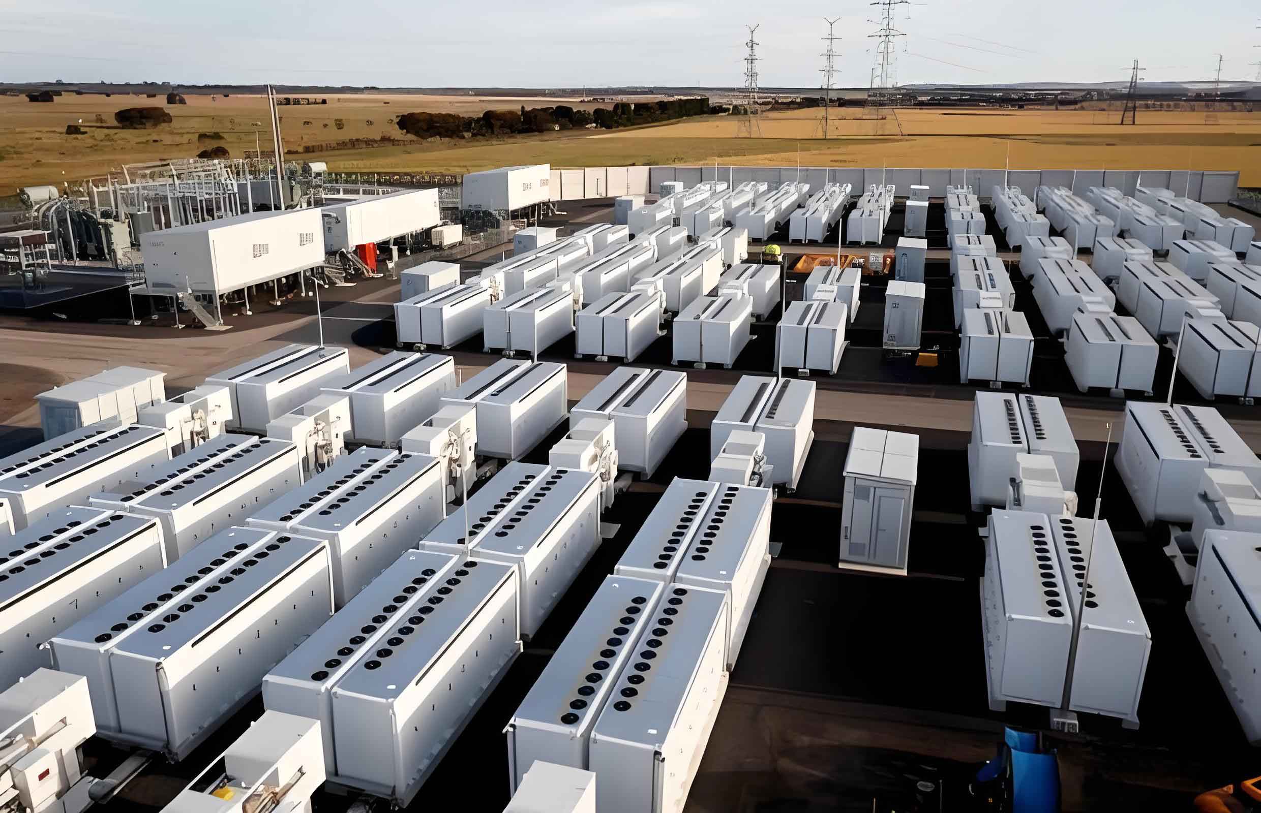
To address these challenges, we explored the applicability of power-type lithium iron phosphate (LFP) batteries in high-rate frequency regulation and fluctuation smoothing scenarios. Our work began with an experimental analysis of the electrical and thermal characteristics of individual cells. Based on these findings, we proposed a liquid-cooled thermal management solution for high-rate applications and designed a 4 MW / 1 MWh frequency regulation lithium battery energy storage system. Subsequently, we constructed a three-dimensional electro-thermal-fluid coupled simulation model of the battery system. The performance of the liquid-cooled thermal management system and the accuracy of the simulation model were validated through experimental testing. Finally, we used numerical simulation to analyze the adaptability of the thermal management system under various all-weather operating conditions.
Electrical and Thermal Characteristics of Power-Type LFP Batteries
To meet the demands of high-rate charge and discharge, power-type lithium batteries are manufactured with smaller electrode material particle sizes and thinner electrode thicknesses, enhancing ionic conductivity and reducing polarization impedance. We selected a 100 Ah power-type lithium iron phosphate battery for our study. A first-order equivalent circuit model (ECM) was used to describe its electrical behavior, and experiments were conducted to obtain its open-circuit voltage and internal resistance.
Ohmic internal resistance is a critical parameter affecting the performance of lithium-ion batteries. It includes the electrolyte impedance and the impedance of the external connection circuit. Using a Hybrid Pulse Power Characteristic (HPPC) test, we determined the battery’s ohmic resistance, polarization resistance, and polarization capacitance under different states of charge (SOC) at a specific temperature. The parameters of the first-order ECM are crucial for modeling the battery’s electrical behavior within the battery energy storage systems. The key parameters obtained from the tests are summarized in Table 1.
| Parameter | Symbol | Value/Description | Unit |
|---|---|---|---|
| Ohmic Internal Resistance | $R_{\Omega}$ | 0.29 – 0.35 | $m\Omega$ |
| Polarization Internal Resistance | $R_p$ | Increases towards the end of discharge | $m\Omega$ |
| Polarization Capacitance | $C_p$ | Negatively correlated with $R_p$ | F |
| Open Circuit Voltage | $U_{OCV}$ | Function of SOC, shown in test results | V |
Experimental results showed that the ohmic internal resistance of this power-type battery remained relatively stable during the mid-discharge phase, slightly increasing near the end. The overall range was between 0.29 and 0.35 m$\Omega$. The polarization resistance gradually increased as the discharge depth progressed. Generally, both the ohmic and polarization internal resistances of the power-type LFP battery are lower than those of energy-type batteries of the same capacity. This results in better rate performance and reduced heat generation. To accurately predict electrical behavior and heat generation via the equivalent circuit model and heat generation model, we also measured the battery’s open-circuit voltage as a function of SOC during the HPPC test.
Table 2 summarizes the temperature rise of the battery at 1C and 4C discharge rates under natural convection cooling in a 25 $^\circ$C ambient environment. Under the 1C rate, the battery temperature reached 30 $^\circ$C at the end of discharge, a rise of about 5 $^\circ$C, which is within the acceptable operating temperature range for lithium batteries. However, at a 4C rate, the battery temperature reached 45 $^\circ$C at the end of discharge, a temperature rise of approximately 20 $^\circ$C. These experimental results strongly indicated that under high-rate charge/discharge conditions, even with power-type lithium-ion batteries, a passive, dissipative thermal management strategy is insufficient for long-term, stable system operation. A more efficient, active thermal management scheme is required. This highlights a key performance requirement for high-power battery energy storage systems.
| Discharge Rate | Ambient Temperature ($^\circ$C) | End-of-Discharge Temperature ($^\circ$C) | Total Temperature Rise ($^\circ$C) |
|---|---|---|---|
| 1C | 25 | 30 | 5 |
| 4C | 25 | 45 | 20 |
Liquid-Cooled Thermal Management System Integration and Simulation Modeling
4 MW/1 MWh Liquid-Cooled Battery Energy Storage System Design
To ensure the lithium battery energy storage system operates within a suitable temperature range under high-rate frequency regulation and fluctuation smoothing conditions, we adopted a liquid-cooled thermal management scheme. The cells measured 173 mm in width, 44 mm in thickness, and 113 mm in height. The battery module used a 1P12S (1 parallel, 12 series) configuration, arranged in a 3-row by 4-column layout. The liquid cooling channel consisted of a 65 mm wide, 6 mm thick micro-channel aluminum flat tube, which was bent and welded with joints to assemble with the batteries. Twelve battery modules were connected in series to form a battery cluster, placed on two trays on the battery rack for easy modular maintenance. The cooling pipes between battery modules were arranged in series, while the cooling pipes between different layers were arranged in parallel. The entire battery cabin housed 8 battery racks, positioned on both sides inside the container, each with its own pump and heat exchanger.
Electro-Thermal-Fluid Coupled Simulation Model
We developed a lithium battery electrical model based on the first-order equivalent circuit. The battery’s electrical behavior is represented by Thevenin’s theorem, allowing for calculation of terminal voltage and heat generation based on the applied current profile.
The terminal voltage $U$ at time $t$ is given by:
$$U(t) = U_{OCV}(SOC, T) + I(t) R_{\Omega}(SOC, T) + U_p(t)$$
Where the voltage across the RC pair $U_p$ evolves as:
$$U_p(t) = U_p(0) \cdot e^{-\frac{t}{R_p C_p}} + I(t) R_p(SOC, T) \left( 1 – e^{-\frac{t}{R_p C_p}} \right)$$
The total heat generation rate $\dot{Q}_{gen}$ is calculated using the Bernardi equation, which considers both irreversible heat ($Q_{ir}$) and reversible entropic heat ($Q_{re}$):
$$\dot{Q}_{gen} = \dot{Q}_{ir} + \dot{Q}_{re} = I (U_{OCV} – U) – I T \frac{dU_{OCV}}{dT}$$
Here, $U_{OCV}$, $R_{\Omega}$, $R_p$, and $C_p$ are functions of SOC and temperature, obtained from experimental characterization. $dU_{OCV}/dT$ is the entropic heat coefficient, also measured experimentally.
The thermal-fluid coupling simulation was performed using a computational fluid dynamics (CFD) solver based on the finite volume method (FVM). The electrical and heat generation models were implemented via user-defined functions (UDFs). The governing equations solved in the simulation are:
Continuity equation for the fluid:
$$\frac{\partial \rho}{\partial t} + \nabla \cdot (\rho \mathbf{u}) = 0$$
Momentum conservation equation (Navier-Stokes) for the fluid:
$$\frac{\partial}{\partial t} (\rho \mathbf{u}) + \nabla \cdot (\rho \mathbf{u} \mathbf{u}) = – \nabla P + \nabla \cdot (\mu \nabla \mathbf{u})$$
Energy equation for the fluid domain:
$$\frac{\partial}{\partial t} (\rho c_p T) + \nabla \cdot (\rho c_p \mathbf{u} T) = \nabla \cdot (k \nabla T)$$
Energy equation for the solid domains (battery and cooling pipe):
$$\frac{\partial}{\partial t} (\rho c_p T) = \nabla \cdot (k \nabla T) + \dot{Q}_{gen}$$
The thermal properties for the working fluid, cooling pipe, and battery used in the simulations are listed in Table 3.
| Material | Density, $\rho$ (kg/m$^3$) | Thermal Conductivity, $k$ (W/(m$\cdot$K)) | Specific Heat, $c_p$ (J/(kg $\cdot$K)) | Dynamic Viscosity, $\mu$ (Pa$\cdot$s) |
|---|---|---|---|---|
| Coolant | 1075 | 0.387 | 3300 | 0.0015 |
| Aluminum Cooling Pipe | 2719 | 202.4 | 871 | – |
| Lithium-ion Battery (Jellyroll) | 1855.9 | Thickness direction: 1.2 In-plane: 20.0 |
1343 | – |
Model Validation
To validate the accuracy of the battery heat generation model and the liquid cooling simulation, we conducted a single-cell experiment under a 4C discharge rate with liquid cooling. The experimental and simulation conditions were set with an initial system temperature of 25 $^\circ$C, a coolant flow rate of 3 L/min per module, and a constant coolant inlet temperature of 25 $^\circ$C. The results showed that under liquid cooling, the battery temperature rise during the 4C discharge was only about 5 $^\circ$C, a significant improvement over natural convection. The simulated temperature rise curve and maximum temperature closely matched the experimental data, with a maximum relative error within 3%, confirming the model’s validity for simulating the coupled electro-thermal-fluid behavior of battery energy storage systems.
Thermal Management Performance Analysis Under High-Rate Frequency Regulation
Using the validated numerical simulation model, we investigated the thermal management capability of the liquid-cooled battery energy storage system under several high-rate conditions. The simulation cases are outlined in Table 4.
| Case ID | Operating Condition | Coolant Flow Rate (L/min/module) | Coolant Inlet Temp ($^\circ$C) | Initial System Temp ($^\circ$C) |
|---|---|---|---|---|
| Case 1 (Baseline) | 4C constant current discharge | 3.0 | 25 | 25 |
| Case 2 | 4C constant current discharge | 1.5 | 25 | 25 |
| Case 3 | Actual AGC frequency regulation cycle | 3.0 | 25 | 25 |
Liquid Cooling Performance Under 4C Constant Current Discharge
For Case 1 (4C discharge, 3 L/min/module), the simulation results showed that as the discharge progressed, the battery temperature increased, reaching a maximum of approximately 32.8 $^\circ$C at the end of discharge. This is well within the ideal operating temperature range for lithium-ion batteries. The temperature difference between the batteries gradually increased to about 3 $^\circ$C by the end of the discharge. The maximum battery temperature rise was 7.8 $^\circ$C, and the coolant temperature rise at the outlet was about 4.1 $^\circ$C. The temperature rise curve exhibited a parabolic shape, where the battery heated up quickly initially, and the rate of temperature increase slowed over time. This behavior occurs because the constant inlet coolant temperature creates a larger temperature gradient between the battery and the coolant as the battery heats up, enhancing the heat transfer rate. When the heat removed by the coolant equals the heat generated by the battery, thermal equilibrium is approached. This demonstrates that this cooling scheme can effectively maintain the batteries within a safe and efficient operating temperature range even during prolonged high-rate operation of battery energy storage systems.
Effect of Coolant Flow Rate on Liquid Cooling Performance
Case 2 investigated the impact of reducing the coolant flow rate to 1.5 L/min/module. At this lower flow rate, the maximum battery temperature at the end of the 4C discharge reached 36 $^\circ$C, and the maximum temperature difference between batteries increased significantly to 7 $^\circ$C. The reduced flow rate lowers the fluid velocity within the cooling channels, leading to a longer residence time for the coolant. Consequently, the coolant temperature at the outlet is higher than in the high-flow case, resulting in a larger performance difference in heat transfer between the inlet and outlet positions and, therefore, a greater battery-to-battery temperature variation. Operating batteries with such a large temperature non-uniformity for extended periods can cause inconsistent aging and degradation, hindering the overall performance and lifespan of the battery energy storage systems. This analysis is summarized in Table 5.
| Coolant Flow Rate (L/min/module) | Max Battery Temperature ($^\circ$C) | Max Inter-Cell Temperature Difference ($^\circ$C) | Max Battery Temperature Rise ($^\circ$C) | Coolant Temperature Rise at Outlet ($^\circ$C) |
|---|---|---|---|---|
| 3.0 | ~32.8 | ~3.0 | 7.8 | ~4.1 |
| 1.5 | ~36.0 | ~7.0 | 11.0 | ~9.0 |
Thermal Management Performance Under High-Rate Frequency Regulation
Grid frequency fluctuations result from the cumulative imbalance of power in the grid. Actual AGC tasks are typically long-duration, continuous frequency regulation processes, during which the battery energy storage systems are required to charge and discharge repeatedly. In Case 3, we simulated the system’s response to an actual AGC current profile. The 15,000-second current profile and the corresponding calculated heat generation profile from the battery were used as inputs. The heat generation remained consistently high, around 65,000 W/m$^3$, due to the frequent 4C charge/discharge cycles. The simulation results showed that, due to the thermal inertia of the system, the battery temperature and outlet coolant temperature curves were smoother than the rapidly changing current and heat generation curves. Throughout the long-term AGC cycle, the maximum battery temperature remained below 33.5 $^\circ$C. In the relatively steady state of the simulation, the temperature difference between the cells in the battery pack was within 2 $^\circ$C. The performance metrics for this case are summarized in Table 6.
| Operating Condition | Max Battery Temperature ($^\circ$C) | Max Inter-Cell Temperature Difference ($^\circ$C) | Coolant Inlet Temperature ($^\circ$C) |
|---|---|---|---|
| Actual AGC Frequency Regulation Cycle | < 33.5 | < 2.0 | 25 |
These results provide strong evidence that our designed liquid-cooled thermal management system is capable of maintaining the battery pack at a safe and uniform temperature for long-term, stable operation under demanding 4C-rate frequency regulation conditions. This demonstrates the viability of such a system for high-performance battery energy storage systems in grid ancillary services.
Conclusion
In this work, we conducted experimental testing on a 100 Ah power-type lithium iron phosphate battery to characterize its electrical and thermal behavior. At a 4C charge/discharge rate and an ambient temperature of 25 $^\circ$C, the maximum temperature of a single cell approached 50 $^\circ$C under natural convection, which is insufficient for safe and prolonged frequency regulation. We also experimentally determined the open-circuit voltage and terminal voltage characteristics as a function of SOC/DOD, providing essential parameters for our thermal simulation model.
We designed a liquid-cooled thermal management scheme for a battery pack and developed a coupled electro-thermal-fluid numerical simulation model. The model was validated against experimental data, showing strong agreement. We then used the model to analyze the system’s performance under 4C constant current discharge, at different coolant flow rates, and under an actual AGC frequency regulation cycle. The simulation results conclusively prove that the proposed liquid-cooled thermal management solution can ensure the long-term, stable operation of battery energy storage systems at high rates (4C). Under realistic AGC frequency regulation conditions, our simulation showed that the temperature difference between batteries remained below 2 $^\circ$C and the maximum temperature was less than 33 $^\circ$C. This research confirms that liquid-cooled thermal management is a critical enabling technology for the reliable and efficient deployment of high-power battery energy storage systems in demanding grid frequency regulation applications.