
In recent years, the adoption of solar photovoltaic systems in rural areas has surged, driven by the need for sustainable energy and economic development. As an integral part of rural infrastructure, these solar systems convert sunlight into electricity, powering homes, agricultural equipment, and supporting “photovoltaic + agriculture” models. However, the widespread deployment of solar systems in open rural environments exposes them to significant lightning threats, which can compromise safety and operational integrity. In this article, I will delve into the mechanisms of lightning damage to solar systems and propose comprehensive protection strategies, leveraging tables and formulas to summarize key insights. My goal is to provide a detailed guide to safeguard these vital solar systems against lightning-induced failures.
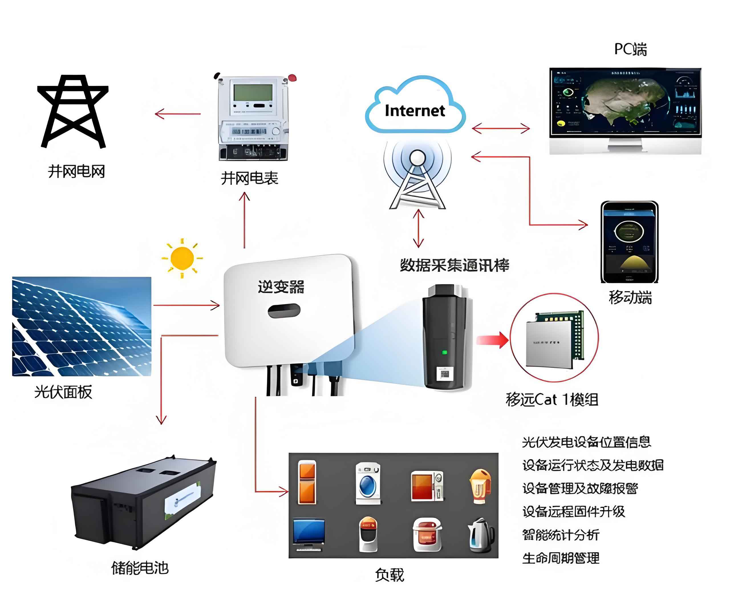
The solar system, comprising solar panels, inverters, and distribution units, is particularly vulnerable due to its low operating voltage and metallic components. Lightning strikes pose two primary hazards: direct strikes and induced surges. A direct strike involves high-current discharge that can thermally and mechanically destroy solar panels and electronics, while induced surges arise from residual charges on conductors, leading to spark discharges and equipment damage. Understanding these mechanisms is crucial for designing robust protection for any solar system. I will analyze both aspects in detail, emphasizing practical measures to enhance the resilience of rural solar systems.
Lightning Hazards to Solar Photovoltaic Systems
Lightning damage to a solar system stems from the immense energy and electromagnetic effects associated with thunderstorms. The solar system, often installed on rooftops or open grounds, acts as a prominent target due to its extensive metallic framework. The two main hazard types are summarized in Table 1.
| Hazard Type | Mechanism | Impact on Solar System | Key Parameters |
|---|---|---|---|
| Direct Lightning Strike | High-current discharge (e.g., 10-200 kA) directly hits the solar system components. | Thermal melting of solar cells, glass breakage, and destruction of inverters and wiring. | Peak current (Ipeak), duration (τ), energy: $$E = \int I(t)^2 R \, dt$$ where R is resistance. |
| Induced Lightning Surge | Electromagnetic induction from nearby strikes creates high-voltage surges on conductors. | Insulation breakdown, sparking across connections, and damage to sensitive electronics. | Induced voltage (Vind): $$V_{ind} = M \frac{dI}{dt}$$ where M is mutual inductance. |
For a direct strike, the thermal energy dissipated can be approximated by the formula: $$Q = I^2 R t$$ where I is the lightning current, R is the system impedance, and t is the duration. This can exceed the tolerance of solar panels, which typically have low withstand levels. In contrast, induced surges in a solar system arise from rapid changes in lightning current, generating transient voltages that propagate along cables. The residual charge after a cloud discharge creates a high potential difference, leading to arcs. For instance, if a solar system has metallic frames with accumulated charge, the voltage relative to ground can be expressed as: $$V = \frac{Q}{C}$$ where Q is the charge and C is the capacitance. This highlights the need for effective grounding and surge protection in every solar system installation.
Direct Lightning Protection System for Solar Systems
To mitigate direct strikes, a solar system requires a well-designed external protection system comprising air-termination networks, down-conductors, and grounding. For large solar arrays, the metal frames of panels can serve as natural air-terminations if their thickness exceeds 3 mm, as per standards. This integrates protection into the solar system itself. If dedicated air-terminations are needed, they should be placed on the north side to avoid shadowing on panels, which could reduce efficiency. The height must minimize shading effects, and down-conductors should be spaced no more than 25 m apart. The lightning current dispersion can be modeled using the equivalent circuit of a solar system under strike: $$V_{strike} = L \frac{dI}{dt} + I R_g$$ where L is inductance and Rg is ground resistance. Key design points are summarized in Table 2.
| Component | Design Specification | Rationale |
|---|---|---|
| Air-termination (e.g., panel frames) | Use metal borders with thickness > 3 mm; install dedicated rods on north side if needed. | To intercept lightning and divert current away from sensitive parts of the solar system. |
| Down-conductors | Utilize metal supports or building steel; max spacing ≤ 25 m for dedicated conductors. | To ensure low-impedance path for current flow to ground in the solar system. |
| Grounding System | Achieve impulse resistance ≤ 4 Ω (or ≤ 30 Ω in high-resistivity soils). | To dissipate energy safely and protect the entire solar system from potential rise. |
In practice, the solar system’s grounding network must be integrated with structural elements. For example, the impulse resistance can be estimated using the formula for a vertical electrode: $$R_{imp} = \frac{\rho}{2\pi L} \ln\left(\frac{4L}{d}\right)$$ where ρ is soil resistivity, L is length, and d is diameter. This ensures that the solar system remains stable during a strike.
Grounding Design Essentials for Solar Systems
Grounding is pivotal for the safety of a solar system, as it provides a reference potential and dissipates fault currents. For ground-mounted solar systems, the reinforced concrete foundations or screw piles can serve as natural grounding electrodes. The impulse grounding resistance should ideally be below 4 Ω, but in high-resistivity areas, up to 30 Ω is acceptable. A common grounding approach is recommended, combining lightning protection, safety grounding, and structural grounding for the solar system. The total resistance can be calculated using parallel resistance formulas: $$R_{total} = \left( \sum \frac{1}{R_i} \right)^{-1}$$ where Ri are individual electrode resistances. This unified grounding minimizes step and touch potentials around the solar system. Table 3 outlines key grounding parameters.
| Parameter | Value/Range | Notes for Solar System |
|---|---|---|
| Impulse Ground Resistance | ≤ 4 Ω (standard); ≤ 30 Ω (high-resistivity soils) | Critical for limiting voltage rise in the solar system during a strike. |
| Electrode Type | Natural (foundations) or dedicated (rods, grids) | Should be corrosion-resistant and integrated with solar system structure. |
| Connection Resistance | ≤ 0.03 Ω at bonding points | Ensures effective equipotentialization across the solar system. |
By optimizing grounding, the solar system can handle both direct and induced threats more effectively. The voltage gradient near the solar system can be derived from: $$V(x) = \frac{I \rho}{2\pi x}$$ where x is distance from the electrode, aiding in safety assessments.
Induced Lightning and Surge Protection Measures
Induced surges pose a stealthy risk to the electronic components of a solar system, such as inverters and controllers. Protection involves equipotential bonding, shielding, proper cabling, and surge protective devices (SPDs). For a solar system, all metallic parts should be bonded to minimize potential differences. The bonding resistance must not exceed 0.03 Ω to prevent sparking. Shielding can be achieved by using armored cables or conduits, which reduce the loop area exposed to electromagnetic fields. The induced voltage in a loop of area A is given by: $$V_{loop} = -A \frac{dB}{dt}$$ where B is magnetic flux density. Thus, minimizing loop area in the solar system wiring is crucial. Additionally, SPDs are installed at critical points like combiner boxes and inverters to clamp surge voltages. The protection level should satisfy: $$U_p/f < 0.8 \times U_{w}$$ where Up/f is the voltage protection level and Uw is the equipment withstand voltage. This ensures the solar system’s electronics remain safe. Table 4 summarizes these measures.
| Measure | Implementation in Solar System | Benefit |
|---|---|---|
| Equipotential Bonding | Connect all metal frames, racks, and enclosures to a common ground bar. | Prevents dangerous potentials within the solar system. |
| Shielding | Use metal conduits or armored cables for wiring; bond shields at both ends. | Reduces electromagnetic coupling to the solar system circuits. |
| Optimal Cabling | Minimize loop areas by routing cables close together and along metal structures. | Lowers induced surges in the solar system. |
| Surge Protective Devices (SPDs) | Install at DC and AC sides; select based on system type (I or II class tests). | Limits transient voltages to safe levels for the solar system. |
For example, in a solar system with long cable runs (>10 m), a two-stage SPD configuration may be needed, with the second stage providing additional clamping. The energy coordination between SPDs can be analyzed using: $$E_{spd} = \int V_{clamp} I \, dt$$ ensuring the solar system is protected without overload.
Configuration Standards for Surge Protective Devices in Solar Systems
SPDs are essential for safeguarding the solar system against transient overvoltages. They should be installed in combiner boxes, distribution cabinets, or inverter enclosures. For building-integrated solar systems, Class I SPDs are preferred, while ground-mounted systems use Class II SPDs. The voltage protection level Up/f must be less than 80% of the equipment’s rated impulse withstand voltage, as per the inequality: $$U_p/f < 0.8 \times U_{imp}$$ where Uimp is the impulse rating. This derating accounts for uncertainties in the solar system’s environment. Additionally, if the cable length from combiner to inverter exceeds 10 m, a second SPD stage is recommended to address induced surges. The wiring should follow a positive-to-equipotential and negative-to-equipotential scheme to avoid common-mode issues. Table 5 details SPD specifications for a typical solar system.
| Parameter | Requirement | Application in Solar System |
|---|---|---|
| SPD Class | Class I for BIPV; Class II for ground-mounted systems | Matches the lightning exposure of the solar system. |
| Voltage Protection Level (Up/f) | Up/f < 0.8 × Uw of protected device | Ensures reliable clamping for the solar system components. |
| Installation Points | DC side: combiner boxes; AC side: inverter output | Protects both DC and AC parts of the solar system. |
| Additional Stage | Required if cable length > 10 m and risk of induced surges | Enhances protection for extended solar system layouts. |
| Wiring Method | Positive and negative poles bonded to equipotential bar | Minimizes loop effects in the solar system. |
The energy handling capability of an SPD in a solar system can be expressed as: $$W = \frac{1}{2} C V^2$$ where C is the capacitance and V is the voltage, though in practice, manufacturers specify this based on tests. Proper SPD selection ensures the solar system operates continuously despite lightning activity.
Conclusion
Lightning protection is a critical aspect of maintaining the reliability and safety of rural solar photovoltaic systems. As solar systems expand in rural areas, their exposure to lightning increases, necessitating robust measures against both direct strikes and induced surges. Through a combination of external protection, effective grounding, equipotential bonding, and strategic use of surge protective devices, the solar system can be shielded from devastating damage. I have outlined key strategies, supported by formulas and tables, to guide the design and implementation of these protections. It is imperative that from installation to maintenance, every solar system incorporates these lightning protection principles to ensure long-term performance and contribute to sustainable rural development. By prioritizing these measures, we can secure the future of solar systems as a cornerstone of green energy in rural communities.