
With the application of smart grids and the advancement of renewable energy generation technology, large-scale and efficient power storage devices have become an important means in the sustainable development of power energy. Liquid flow energy storage batteries have been favored among many power storage technologies due to their advantages such as long cycle life, flexible scale, rapid response, and device safety. Liquid flow energy storage batteries have been put into multiple demonstration projects abroad. The research on liquid flow energy storage batteries started relatively late in China, and the research on automatic energy storage technology for batteries is relatively weak. Currently, liquid flow energy storage batteries have been widely used in China’s power grid. In order to improve the cycle life of liquid flow energy storage batteries, it is necessary to study their automatic energy storage technology.
Propose a study on the response characteristics of temperature stress in an all vanadium liquid flow energy storage battery system. By fitting the functional relationship between equivalent resistance, electromotive force, and state of charge, the automatic energy storage technology of energy storage batteries is studied on the Matlab/Simulink platform. A simulation study on the energy storage system of all vanadium flow energy storage batteries was proposed. By analyzing the basic structure of all vanadium flow energy storage batteries, the working principle and characteristics were studied, and an electrical model of all vanadium flow energy storage batteries was established. Two control strategies for energy storage inverters and power grids were modeled and simulated separately. Analyze the performance of all vanadium liquid flow energy storage batteries with temperature stress changes. Based on the equivalent circuit model, establish an equivalent circuit simulation model in Simulink by combining the dynamic temperature change model, electrolyte flow loss situation, and electron diffusion state, and study the automatic energy storage technology of energy storage batteries. The above two methods did not consider the relevant constraints when studying the energy storage technology of energy storage batteries, resulting in lower wind curtailment improvement rate, annual investment return rate, power generation utilization rate, and Coulomb efficiency of the methods.
In order to solve the problems in the above methods, a large-scale high-efficiency liquid flow energy storage battery automatic energy storage technology is proposed.
1. Energy storage planning model
1.1 Objective function
The goal is to maximize the revenue of the energy storage battery system within the planned level year, and the following objective function is constructed under constraint conditions:
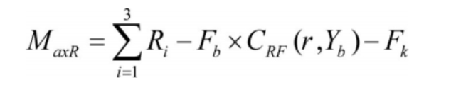
In the formula, Ri represents the capacity substitution efficiency, environmental protection efficiency, and energy efficiency of the static energy storage function of the energy storage battery; Fb represents the investment cost of energy storage batteries, and its calculation formula is as follows:
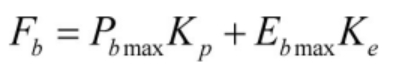
In the formula, Pb max represents the rated power of the liquid flow energy storage battery; Kp represents the unit power of the liquid flow energy storage battery; Eb max represents the electrical capacity of a liquid flow energy storage battery; Ke represents the unit capacity price of liquid flow energy storage batteries.
CRF (r, Yb) represents the equiannual coefficient, which is expressed as:
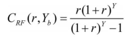
In the formula, r represents the discount rate.
Fk represents the electrical capacity of a liquid flow energy storage battery, which can be calculated using the following formula:
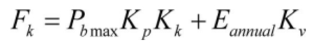
In the formula, Kk represents the fixed operation and maintenance rate of the liquid flow energy storage battery; Representing the annual discharge capacity of liquid flow energy storage batteries; Kv represents the variable operation and maintenance rate of liquid flow energy storage batteries.
(1) Energy conservation benefits
During low and high load periods, the liquid flow energy storage battery is charged and discharged separately. Some of the start-up capacity requirements of thermal power can be replaced by the charging and discharging of the liquid flow energy storage battery mentioned above, reducing fuel consumption and improving the thermal power load rate. The energy saving benefits of the liquid flow energy storage battery are described by the following formula:
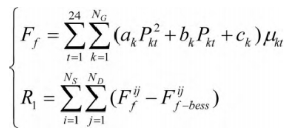
In the formula, NG represents the number of thermal power units in the liquid flow energy storage battery system; Ak, bk, and ck all describe fuel cost coefficients; Pkt represents the output size corresponding to unit k at time t; μ Kt represents the startup status of unit k at time t; Describing the fuel cost before adding a liquid flow energy storage battery to node i; It describes the fuel cost after adding a liquid flow energy storage battery to node i.
(2) Environmental benefits
The consumption of fossil fuels in conventional power units can be reduced through peak shaving and valley filling using liquid flow energy storage batteries, thereby improving environmental benefits and reducing pollutant emissions. Describe the environmental benefits of a liquid flow energy storage battery system using the following equation:
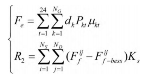
In the formula, dk represents the corresponding sulfur dioxide emission coefficient of unit k in the liquid flow battery system; Representing the sulfur dioxide emissions generated before adding liquid flow battery energy storage in the i-th stage; It represents the amount of sulfur dioxide emissions generated after adding liquid flow battery energy storage in the i-th stage.
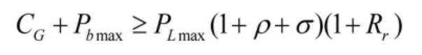
(3) Capacity substitution efficiency
The annual peak load of the system can be reduced through peak shaving and valley filling of the liquid flow energy storage battery system. The capacity substitution efficiency of the liquid flow energy storage battery system can be described by the following equation:

Among them:
In the formula, Rr describes the standby coefficient corresponding to the liquid flow energy storage battery system; PLmax describes the peak load corresponding to the liquid flow energy storage battery system in the current horizontal year; Describing the annual load growth rate corresponding to the liquid flow energy storage battery system; CG represents the installed capacity of the original liquid flow energy storage battery system; YG represents the economic service life of thermal power units in liquid flow energy storage battery systems; KG represents the unit cost of thermal power installed in a liquid flow energy storage battery system.
2.2 Constraints
(1) Power balance constraint
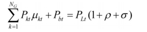
In the formula, PLt represents the corresponding load value of the liquid flow energy storage battery at time t; σ Describing the line loss rate of a liquid flow energy storage battery system; ρ It describes the power consumption rate of the factory.
(2) Backup constraint
Describe the backup constraints of the liquid flow energy storage battery system using the following equation:
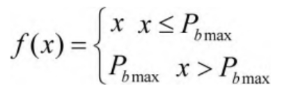
(3) Output constraint
The processing constraints of conventional units in liquid flow energy storage battery systems are described by the following equation:
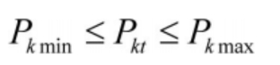
In the formula, Pk min represents the minimum output of unit k in the liquid flow energy storage battery system; Pk max represents the maximum output of unit k in the liquid flow energy storage battery system.
(4) Climbing constraint
The climbing constraint of thermal power units in the liquid flow energy storage battery system can be expressed as:
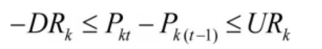
In the formula, DRk represents the lifting speed of unit k in the liquid flow energy storage battery system; URk represents the rate of load reduction of unit k in the liquid flow energy storage battery system.
(5) Running constraints
Describe the operational constraints of a liquid flow energy storage battery system using the following formula:
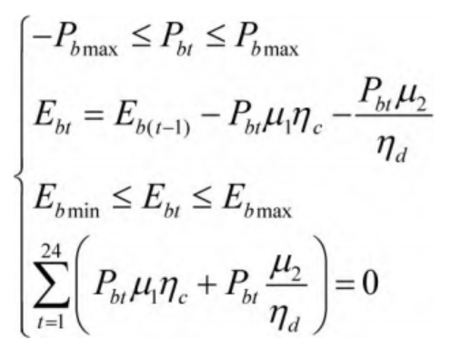
In the formula, Ebt represents the energy stored in the liquid flow energy storage battery; μ 1 represents the charging status of the liquid flow energy storage battery during operation; η C represents the charging efficiency corresponding to the liquid flow energy storage battery; μ 2 represents the discharge state of the liquid flow energy storage battery during operation; η D represents the discharge efficiency of the liquid flow energy storage battery during operation; Eb min describes the minimum energy storage value of a liquid flow energy storage battery.
2. Implementation of automatic energy storage in liquid flow energy storage batteries
The automatic energy storage technology of large-scale and efficient liquid flow energy storage batteries adopts particle swarm optimization algorithm to solve the automatic energy storage planning model of liquid flow energy storage batteries, achieving automatic energy storage of liquid flow energy storage batteries. The particle swarm optimization algorithm has the advantages of fast convergence speed, fewer required adjustment parameters, simple structure, and good robustness.
When using particle swarm optimization algorithm to solve the automatic energy storage planning model of liquid flow energy storage batteries, it is necessary to initialize the velocity and position of particles, and use iterative methods to obtain the optimal values.
The position xik corresponding to particle i in the t-th iteration can be calculated using the following equation:
In the formula, xmin and xmax represent the minimum and maximum positions, respectively.
The velocity vik corresponding to particle i in the t-th iteration can be calculated using the following equation:
In the formula, vmin and vmax represent the minimum and maximum values of speed, respectively. The optimal position of the particle during the search process is zi (t)=[zi1 (t), zi2 (t),…, zid (t)] ^ T, and the optimal position of the particle swarm during the search process is zg (t)=[z g1 (t), z g2 (t),…, z gd (t)].
After the t+1st iteration, update the position and velocity of particle i using the following formula:
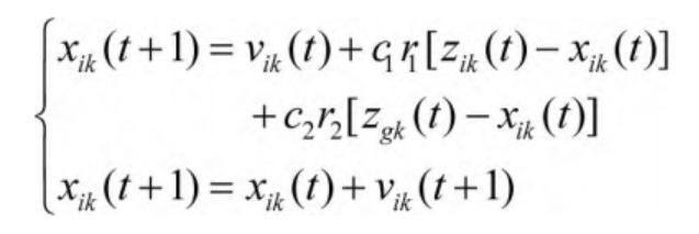
In the formula, r 1 and r 2 are random numbers taking values within the interval [0,1]; Both c1 and c2 represent learning factors.
3. Experiment and Analysis
In order to verify the overall effectiveness of automatic energy storage technology for large-scale high-efficiency liquid flow energy storage batteries, it is necessary to test the automatic energy storage technology for large-scale high-efficiency liquid flow energy storage batteries.
Using the improvement rate of abandoned wind as an indicator, the automatic energy storage technology of large-scale high-efficiency liquid flow energy storage batteries and two methods were tested. The higher the improvement rate of abandoned wind, the better the improvement of abandoned wind and the better the energy storage state of the method. The calculation formula for the improvement rate of abandoned wind RRIAW is as follows:
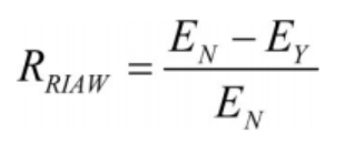
In the formula, EN represents the total amount of wind power curtailment in the presence of liquid flow energy storage batteries; EY represents the total amount of wind power curtailment when there is no liquid flow energy storage battery.
The improvement rates of abandoned wind for the proposed method and two methods are shown in Figure 1.
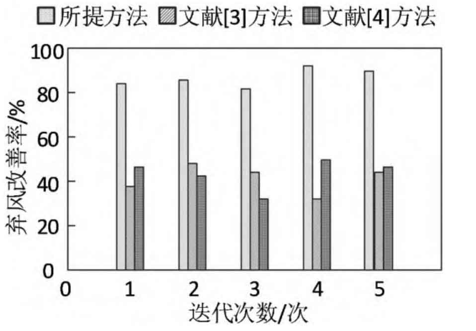
By analyzing the data in Figure 1, it can be seen that the proposed method achieved an improvement rate of over 80% in wind abandonment during the testing process. The improvement rates of wind abandonment obtained by both methods during the testing process were much lower than those of the proposed method. Because the proposed method takes into account output constraints and climbing constraints when constructing an automatic energy storage planning model for liquid flow energy storage batteries, it reduces the abandoned wind rate of the planned liquid flow energy storage battery system.
Using the proposed method and two methods for energy storage planning of liquid flow energy storage batteries, the annual investment return rates of different methods were compared. A high annual investment return rate indicates better energy storage technology, and the annual investment return rates of different methods are shown in the table.
| Experiment number | Annual investment return rate of the proposed method/% | Method 1 year investment return rate/% | Method 2 year investment return rate/% |
| 1 | 1.9 | 0.5 | 0.8 |
| 2 | 1.7 | 0.6 | 0.8 |
| 3 | 1.8 | 0.6 | 0.7 |
| 4 | 1.8 | 0.5 | 0.6 |
| 5 | 1.7 | 0.7 | 0.8 |
| 6 | 1.7 | 0.7 | 0.7 |
| 7 | 1.9 | 0.6 | 0.7 |
| 8 | 1.8 | 0.7 | 0.6 |
| 9 | 1.8 | 0.5 | 0.6 |
| 10 | 1.7 | 0.6 | 0.8 |
By analyzing the data in the table, it can be seen that in multiple experimental tests, the annual investment return rate obtained by the two methods is much lower than that obtained by the proposed method. This indicates that the proposed method can achieve higher investment returns when planning automatic energy storage for liquid flow energy storage batteries, indicating that the proposed method has a higher energy storage effect.
Using power generation utilization rate as an indicator, verify the effectiveness of the proposed method and two methods. The higher the power generation utilization rate, the higher the energy utilization rate stored in the liquid flow energy storage battery, and the better the effectiveness of the method. The power generation utilization test results of the proposed method and two methods are shown in Figure 2.
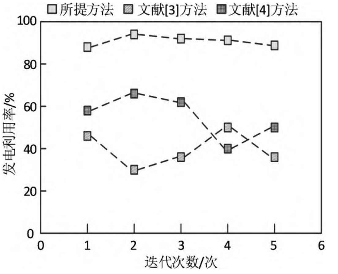
Analyzing the data in Figure 2, it can be seen that the power generation utilization rate obtained by the proposed method in multiple iterations is higher than 80%. In the second iteration, the power generation utilization rate obtained by Method 1 is as low as 30%, and in the fourth iteration, the power generation utilization rate obtained by Method 2 is as low as 40%. Compare the proposed methods and methods
The test results of Method 1 and Method 2 show that the power generation utilization rate of the proposed method is higher than that of Method 1 and Method 2 in multiple iterations, verifying the effectiveness of the proposed method.
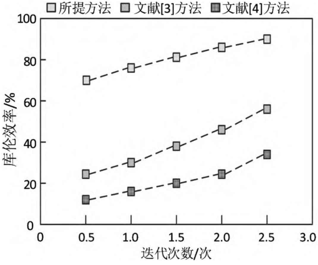
Using the proposed method, method 1, and method 2 for energy storage testing, the Coulombic efficiency of different methods was compared. The higher the Coulombic efficiency, the better the energy storage performance of the method. The test results of the above methods are shown in Figure 3. Analysis of the data in Figure 3 shows that as time goes on, the Coulombic efficiency of all three methods improves. However, at the same time point, the Coulombic efficiency of the proposed method is higher than that of Method 1 and Method 2, indicating that the proposed method has good energy storage performance.
4. Conclusion
Renewable energy has been continuously developing in recent years, with a large number of energy storage systems and distributed power sources integrated into active distribution networks. The comprehensive performance of liquid flow energy storage battery energy storage system in large-scale energy storage technology is high, which can achieve the consumption of renewable energy, regulate grid power, and research on its energy storage technology is of great significance. At present, the automatic energy storage method of liquid flow energy storage batteries has problems such as low wind abandonment improvement rate, low annual investment return rate, low power generation utilization rate, and low Coulombic efficiency. A large-scale and efficient automatic energy storage technology for liquid flow energy storage batteries was proposed, and an energy storage planning model was constructed. The particle swarm optimization algorithm was used to solve it, achieving energy storage planning for energy storage batteries and solving the problems in current methods. However, there is relatively little research on the proposed method in terms of energy storage efficiency. In future work, it is necessary to focus on improving energy storage efficiency.