
The pursuit of safer, more reliable energy storage has consistently driven advancements in lithium-ion battery technology. Among the various chemistries, the lithium iron phosphate (LiFePO4) battery has emerged as a cornerstone for applications demanding high safety and long cycle life, such as electric vehicles and stationary energy storage systems. Its exceptional stability originates from the robust olivine crystal structure of the LiFePO4 cathode material, where the strong P–O covalent bonds in the PO4 tetrahedra prevent oxygen release and structural collapse even under abusive conditions like elevated temperature or overcharge. This inherent stability has often led to the perception of LiFePO4 batteries as being inherently “safe.” However, field incidents and stringent safety certification protocols reveal that under extreme overcharge scenarios, LiFePO4 batteries can still undergo catastrophic failure, including thermal runaway and fire. Understanding the precise failure mechanisms triggered by overcharging is therefore not merely academic but a critical engineering imperative for designing the next generation of high-capacity, high-safety LiFePO4 batteries. This analysis delves into the nuanced failure pathways, with a particular focus on the often-overlooked role of metallic impurity dissolution and deposition.
The overcharge failure of a LiFePO4 battery is a complex, multi-stage process that deviates significantly from that of layered oxide cathodes like NMC or LCO. During normal operation, the electrochemical reactions are well-defined. For the LiFePO4 cathode, the charge process involves the extraction of lithium ions and electrons:
$$ \text{LiFePO}_4 \xrightarrow{\text{charge}} \text{FePO}_4 + \text{Li}^+ + e^- $$
Simultaneously, at the graphite anode, lithium ions are intercalated:
$$ x\text{Li}^+ + x e^- + 6\text{C} \rightarrow \text{Li}_x\text{C}_6 $$
Under overcharge conditions beyond the designed upper voltage limit, these reversible processes are overtaken by a cascade of irreversible parasitic reactions. The voltage of the LiFePO4 battery cell during overcharge can be conceptually broken down as:
$$ V_{\text{cell}}(t) = E_{\text{eq,c}}(t) – E_{\text{eq,a}}(t) + \eta_{\text{c}}(t) + \eta_{\text{a}}(t) + I(t)R_{\Omega}(t) $$
where \( E_{\text{eq,c}} \) and \( E_{\text{eq,a}} \) are the equilibrium potentials of the cathode and anode, \( \eta_{\text{c}} \) and \( \eta_{\text{a}} \) are the overpotentials, \( I \) is the current, and \( R_{\Omega} \) is the ohmic resistance. As overcharge proceeds, \( E_{\text{eq,a}} \) plunges as the anode approaches and surpasses the potential for lithium plating and electrolyte reduction, while \( E_{\text{eq,c}} \) rises into a high-voltage plateau associated with electrolyte oxidation. The cell voltage climb is thus dominated by the increasing anode overpotential and the growing \( IR_{\Omega} \) drop due to the formation of resistive surface films (Solid Electrolyte Interphase – SEI).
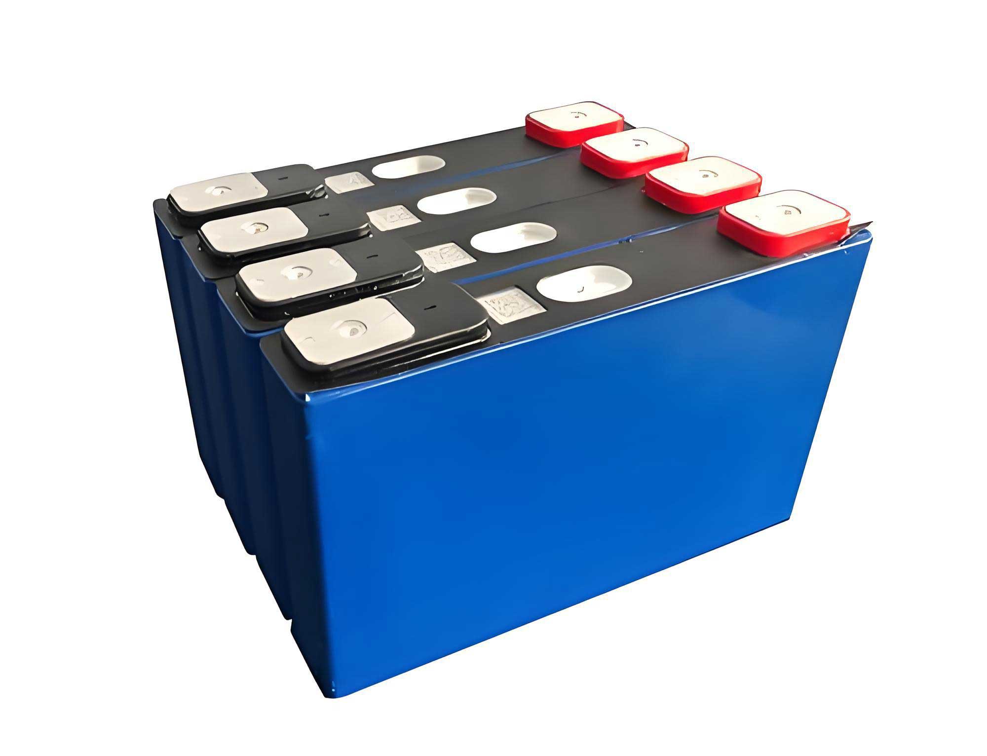
Experimental overcharge tests on commercial-grade 324 Ah prismatic LiFePO4 batteries reveal starkly different behavioral signatures between cells from different production batches, labeled here as Batch-A and Batch-B. Both were subjected to a constant-current overcharge protocol until a cutoff voltage of 5.48 V. The critical parameters—voltage, surface temperature, and internal resistance—were monitored in real-time. The divergence in their failure modes is summarized in the table below, which contrasts the key observational and measured data.
| Parameter | Batch-A LiFePO4 Battery | Batch-B LiFePO4 Battery |
|---|---|---|
| Overcharge Outcome | Test passed. No thermal runaway after reaching 5.48V. | Catastrophic failure. Thermal runaway and fire initiated at ~1070s. |
| Voltage Trajectory | Steady increase to the 5.48V cutoff. | Sudden, sharp drop from ~4.34V to 0V at 1070s, indicating an internal short circuit. |
| Temperature Profile | Peak temperature of 83°C at cutoff. | Rapid temperature spike from 103°C to >500°C following the voltage collapse. |
| Internal Resistance (RΩ) Trend | Significant and steady increase from 0.35 mΩ to 1.50 mΩ (ΔR = +1.15 mΩ). | Minimal increase from 0.32 mΩ to 0.36 mΩ prior to short (ΔR = +0.04 mΩ). |
| Post-Mortem Anode Visual (R-corner) | Uniform golden/yellow hue, minor dark spots from SEI. | Pronounced grayish-black to dark brown discoloration localized at the R-corner. |
The internal resistance trend is particularly illuminating. In a typical overcharged LiFePO4 battery, like Batch-A, the continuous growth of thick, resistive decomposition products on both electrodes leads to a substantial increase in \( R_{\Omega} \). In contrast, the negligible \( \Delta R \) in Batch-B before failure suggests the formation of a highly conductive byproduct that effectively shunts the resistive films. This early clue pointed towards a metallic deposition mechanism rather than mere electrolyte decomposition.
Post-mortem dissection of cells stopped at various stages of overcharge provided visual confirmation. While Batch-A anodes remained largely unchanged, Batch-B anodes exhibited a progressive darkening, specifically concentrated at the curved “R-corner” of the jellyroll—a region known for higher mechanical stress and potentially different current density. This localized phenomenon suggested a site-specific accumulation of material.
To quantify this observation, Inductively Coupled Plasma (ICP) analysis was performed on scrapings from the anode R-corner. The data reveals an explosive growth in iron content exclusively in the Batch-B LiFePO4 battery.
| Overcharge Duration (s) | Li Content (wt%) | Fe Content (wt‰, ppm) | Fold Increase in Fe (vs. 0s) |
|---|---|---|---|
| 0 (Fresh) | 5.56 | 0.01 ‰ (10 ppm) | 1.0 |
| 504 | 5.60 | 0.17 ‰ (170 ppm) | 17.0 |
| 720 | 5.57 | 1.44 ‰ (1440 ppm) | 144.0 |
| 936 | 5.59 | 2.74 ‰ (2740 ppm) | 274.0 |
| Batch-A @ 936s | ~5.6 | 0.07 ‰ (70 ppm) | 7.0 |
The iron content in the Batch-B anode increased by over 270 times compared to its initial state, and was nearly 40 times higher than in the Batch-A LiFePO4 battery at the same overcharge stage. This massive iron deposition, or “iron plating,” is the decisive failure step. The source of this iron was traced back to the cathode. While both cathodes showed expected iron loss from the active LiFePO4 material due to dissolution at high voltage, Scanning Electron Microscopy with Energy Dispersive Spectroscopy (SEM-EDS) identified a critical difference: the presence of rod-shaped impurity particles in the Batch-B cathode material. These impurities had an iron content of 33.22 wt%, significantly higher than the 26.08 wt% in the standard LiFePO4 matrix. Under the harsh oxidative potential of overcharge, these impurity sites act as preferential points for accelerated iron dissolution, described by a kinetic rate that can be simplified as:
$$ \frac{d[Fe^{2+}]_{sol}}{dt} = k_{LFP} \cdot A_{LFP} \cdot f(E) + k_{imp} \cdot A_{imp} \cdot g(E) $$
where \( k_{imp} >> k_{LFP} \) and \( g(E) \) is a stronger function of the elevated potential \( E \) than \( f(E) \), making impurity dissolution the dominant source of soluble Fe2+ ions.
These dissolved Fe2+ ions migrate through the electrolyte. At the severely polarized anode (now at a potential far below 0 V vs. Li/Li+), they are readily reduced and deposited as metallic iron:
$$ \text{Fe}^{2+} + 2e^- \rightarrow \text{Fe}^0 $$
This reduction competes with and can even precede massive lithium plating. The deposited iron does not form a smooth layer but grows as dendrites or porous structures. Crucially, cross-sectional SEM-EDS analysis of the separator from the failure zone in the Batch-B LiFePO4 battery showed that these iron structures had propagated through and fully infiltrated the pores of the polyethylene separator base layer, creating a continuous metallic bridge between the anode and the ceramic-coated side facing the cathode.
This phenomenon transforms the local separator from an ionic insulator to an electronic conductor. The resulting internal short circuit has a very low resistance, \( R_{short} \), leading to an immense local current, \( I_{short} = \Delta V / R_{short} \), where \( \Delta V \) is the potential difference between the electrodes. The instantaneous Joule heating, \( Q = I_{short}^2 R_{short} t \), is sufficient to trigger local thermal runaway, which then propagates throughout the cell, explaining the sudden voltage drop and temperature spike observed in the Batch-B LiFePO4 battery.
The short circuit has another profound consequence: it acts as an uncontrolled discharge pathway. Lithium ions from the plated lithium or the intercalated graphite anode are driven back into the cathode. This is conclusively proven by X-ray Diffraction (XRD) and half-cell diagnostics on harvested cathodes. The XRD pattern of the Batch-B cathode from the cell overcharged to 936s showed the re-emergence of LiFePO4 peaks alongside the dominant FePO4 phase, indicating partial re-lithiation. Electrochemical testing of these cathodes in laboratory coin cells provided definitive evidence:
| Overcharge Duration (s) | 1st Discharge Capacity (0.05C, mAh/g) | 2nd Discharge Capacity (mAh/g) | Capacity Retention vs. 0s |
|---|---|---|---|
| 0 | 160.91 | 163.75 | 100% (Baseline) |
| 504 | 161.71 | 163.83 | ~100% |
| 720 | 160.41 | 162.25 | ~99% |
| 936 | 92.21 | 160.15 | 57.3% (1st cycle) |
The dramatically reduced first-cycle capacity for the 936s cathode directly results from the short-circuit-induced re-lithiation, which occupied active sites within the FePO4 host, leaving fewer vacancies for subsequent electrochemical lithium intercalation during the coin cell test. While the structure recovers some reversibility in the second cycle, the initial capacity loss and the structural disorder indicated by peak broadening in XRD confirm the damaging impact of the internal short circuit on cathode integrity.
In conclusion, the failure of the LiFePO4 battery under overcharge is not a simple story of electrolyte decomposition and gas production. This analysis reveals a more pernicious chain of events, particularly in cells containing cathode material with metallic impurities: 1) Preferential Dissolution: Iron from impurity sites in the cathode dissolves at high voltage. 2) Migration and Deposition: Fe2+ ions migrate and are reduced to metallic Fe0 at the overcharged anode, primarily at high-stress points like the R-corner. 3) Separator Bridging: The deposited iron grows through the separator pores, creating a conductive metal bridge. 4) Internal Short Circuit: The low-resistance bridge causes a sudden, high-current internal short, leading to localized Joule heating. 5) Thermal Runaway: The heat triggers decomposition of the SEI, electrolyte, and other components, culminating in cell venting, fire, or explosion. 6) Uncontrolled Discharge: The short circuit forces Li+ back into the cathode, causing irreversible capacity loss and structural damage.
This mechanism underscores that the safety of a LiFePO4 battery is not guaranteed by its bulk chemistry alone. The presence of trace metallic impurities, especially iron, can create a decisive failure pathway during electrical abuse. Therefore, improving the overcharge tolerance of high-capacity LiFePO4 batteries must focus on material purity, particularly the rigorous elimination of iron-bearing impurities in the cathode synthesis process. Furthermore, cell design should consider current distribution and mechanical stress to minimize localized plating hotspots. Separator technologies with enhanced mechanical strength and pore structure to resist metal penetration are also critical. By addressing these root causes, the intrinsic safety advantages of the LiFePO4 battery can be fully realized, paving the way for more robust energy storage solutions.