
With the intensification of energy scarcity and environmental pollution, solar energy has become the preferred renewable and pollution-free energy source. Solar energy, with its extensive and clean advantages, has received great attention from people. Solar photovoltaic power generation technology has significant significance in alleviating energy problems and improving the environment, so it has broader development prospects. At the same time, solar inverters are an essential component in solar photovoltaic power generation systems. Solar photovoltaic power generation inverters can be divided into independent control inverters and grid connected inverters based on their usage. Regardless of the type of solar inverter, our research on it is divided into two aspects: control mode and topology structure, and we propose a research method of precise linearization through state feedback.
Adopting quadratic optimal control to achieve control of solar inverters, a corresponding model was established in the Matlab/Simulink environment. Through comparison of simulation results, its superiority was demonstrated and a basis was provided for the design of solar inverters.
1. Structure of solar photovoltaic inverters
1.1 Topological structure of solar photovoltaic inverters
An inverter is a device that can convert direct current into alternating current. Solar inverters can convert the direct current voltage output by solar panels into sinusoidal alternating current, which is then filtered and integrated into the power supply network. Inverter circuits have various topological structures, such as half bridge inverter circuits and full bridge inverter circuits. The typical structure of a solar inverter is generally a full bridge inverter circuit composed of four power transistors, as shown in Figure 1. In order to reduce the harmonic components of the output sinusoidal alternating current, we adopted a filtering circuit composed of inductors and capacitors to filter the harmonic components.
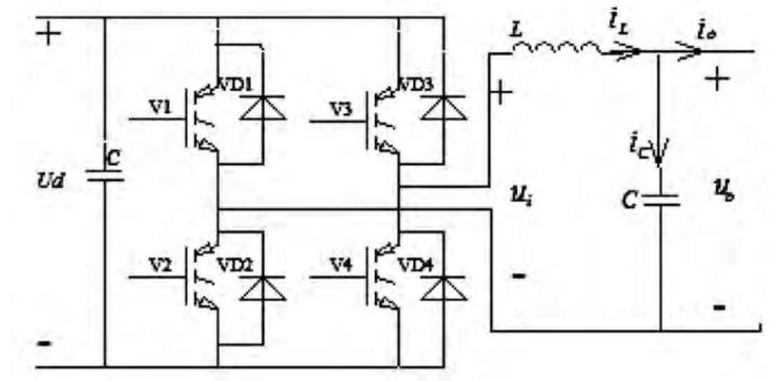
In Figure 1, V1 and V2 are IGBT power transistors on the high-voltage side, V3 and V4 are IGBT power transistors on the low-voltage side, and ui is the output high-frequency sine wave voltage; L is the filtering inductance; C is the filtering capacitor; The equivalent resistance of the circuit is ignored.
The filtering circuit is composed of inductance L and capacitance C; The filtered output Uo is the grid voltage. The left and right arms of the main circuit inverter bridge are respectively equipped with sine wave pulses with a phase difference of 180 degrees. After filtering out the harmonic components through the filtering circuit on the AC side, a sinusoidal current with the same frequency and initial phase as the mains network is output.
1.2 Mathematical model of solar inverters
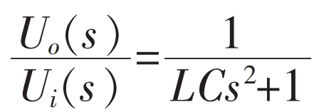
The input-output relationship of the solar inverter system during no-load operation is shown in the formula.
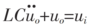
The equation of motion can be obtained from the formula:
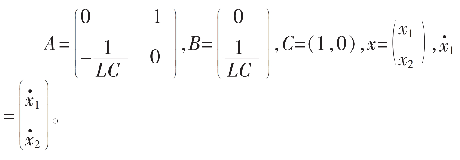
If x1 and x2 are state variables and x1=uo, x2=· uo, the state equation can be obtained as follows:
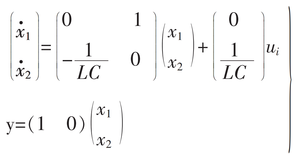
The formula shows the state space representation of the mathematical model of the solar inverter when it is unloaded.
2. Principle of optimal control
The optimal control problem is essentially a variational problem. However, classical variational theory can only solve a class of optimal control problems where the admissible control belongs to an open loop set. In practice, many admissible control problems belong to a class of optimal control problems in closed sets, so more methods for solving optimal control are needed. The most commonly used methods to solve the most control problems are the minimum principle and dynamic programming.
The problem studied by optimal control theory can be summarized as: for a controlled dynamic system or motion process, finding an optimal control scheme from a class of allowed control schemes, so that the performance index value of the system is optimal when the motion is transferred from an initial state to a specified target state.
To elaborate on the optimal control problem, three basic elements are required: the mathematical model of the controlled object/system, physical constraints, and performance indicators.
The reason why the optimal regulator has excellent characteristics is because it uses feedback from all state information of the system. If all state information can be directly measured, then the implementation of the optimal system is very simple. However, in practical engineering, some states are difficult to measure directly, and even if they can be measured directly, there will be a significant cost to pay. At this point, if all the states of the system are reconstructed based on several easily measurable state information to form the feedback required for the optimal regulator, the above difficulties can be overcome.
A state observer is a type of system that can reconstruct the dynamic links of the original system based on the input and measurement outputs of the original system. It provides not the true state of the original system, but an estimate of the true state. The estimated value will become closer to the true value over time. This makes it possible to use estimated state feedback to achieve optimal regulation of the system.
3. Quadratic optimal control of inverter systems
For the single input linear system shown in the formula, it can be known that {A, B} is completely controllable, and {A, C} is completely observable, indicating the existence of a unique optimal output regulator for the system.
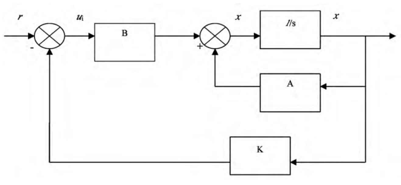
The structural diagram of the quadratic optimal control system based on the system state equation can be obtained from the formula, as shown in Figure 2.
Figure 2:
The objective function is:
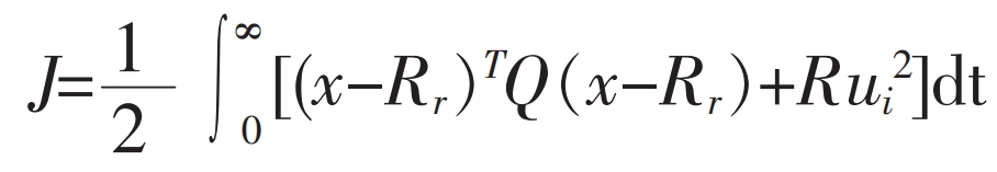
In the equation, (C1 is a normal number), R=1, then the objective function is:
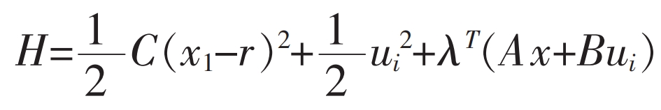
The goal of optimization is to obtain the optimal feedback K and ui * to minimize the objective function J. Set:
Due to the covariance equation being:
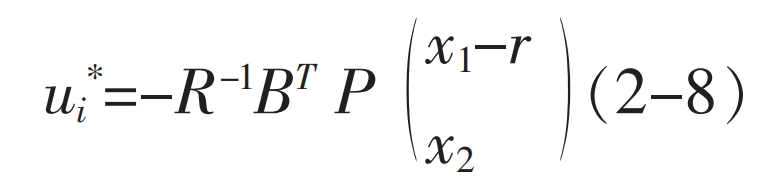
Therefore, the optimal solution is:
Namely:
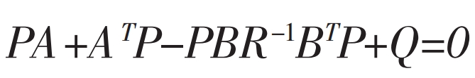
Among them, P satisfies the Riccati algebraic equation:
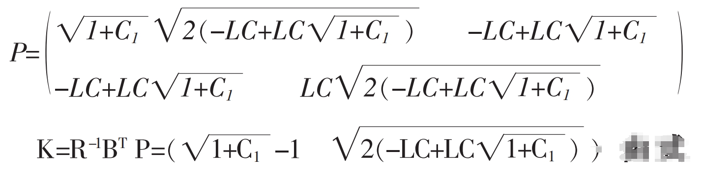
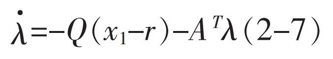
The solution can lead to:
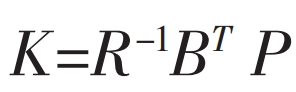
From the formula, it can be concluded that:
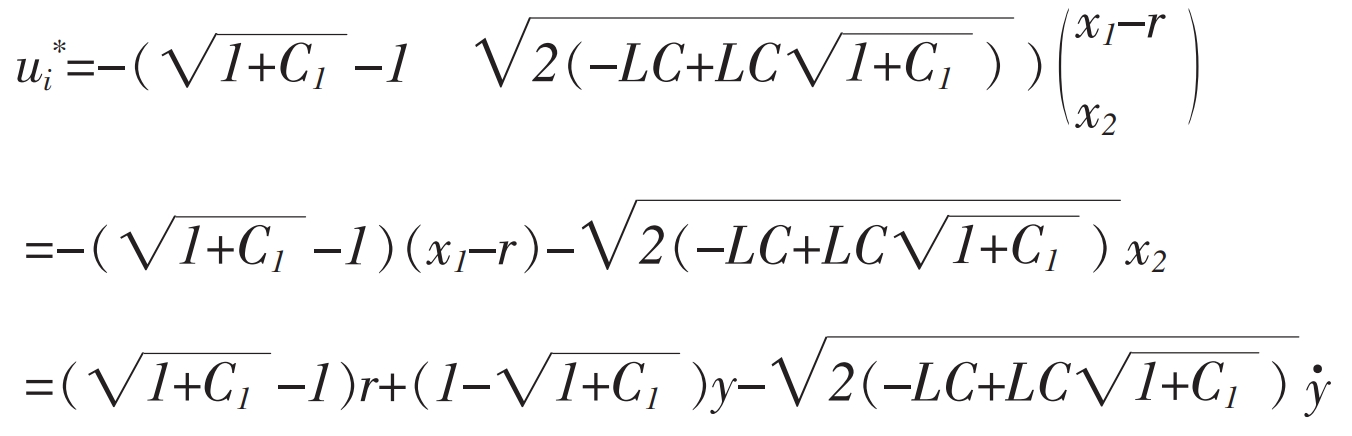
Among the above, u * and K are the optimal control solution and optimal feedback solution obtained.
4. Experimental results
Take the switching frequency as 20kHz; The reference input is 220V, the filtering inductance L=1.6mH, and the filtering capacitance C=400uF.
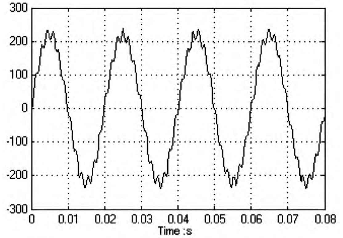
Figure 3 shows the output voltage of the original system at no load, while Figure 4 shows the output voltage of the system at no load during optimal adjustment.
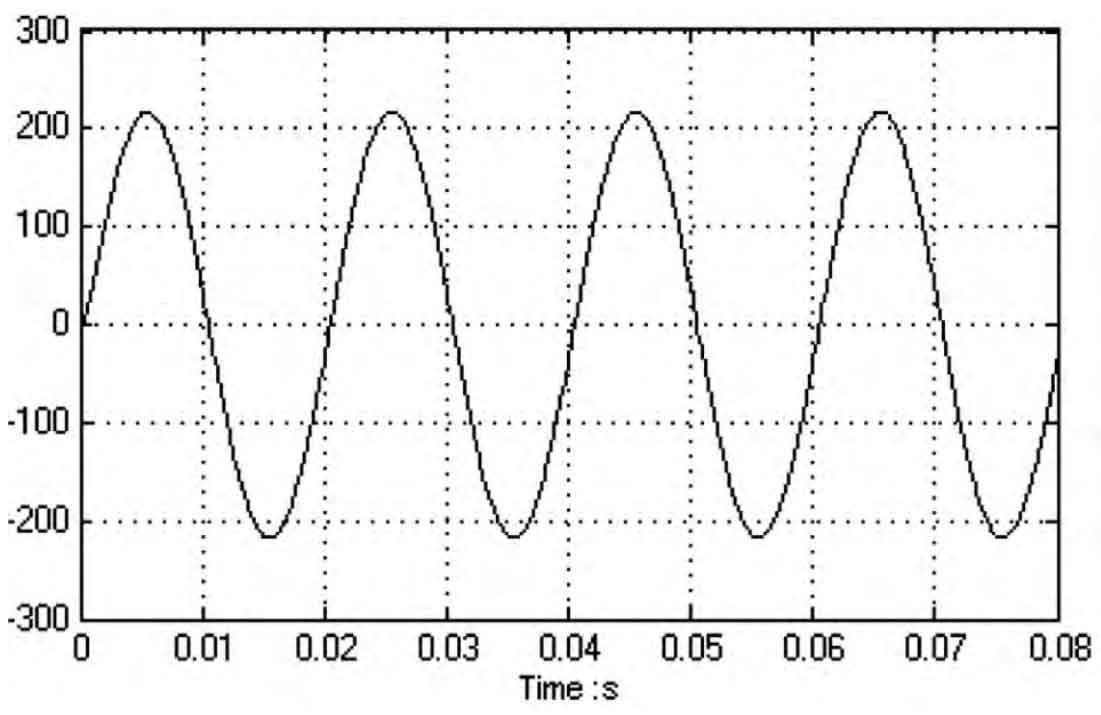
Through simulation analysis using simulation software, it can be seen that the waveform distortion rate of the original system shown in Figure 3 is 25.6% when unloaded, and there are burrs. The waveform distortion rate of the system at no-load is 3.8% under the optimal control shown in Figure 4, and it can be clearly seen from Figure 4 that the waveform is smooth and approximately standard sine wave.
Therefore, with the use of the quadratic optimal control method described in this article, the output voltage quality of the system is significantly improved.
5. Conclusion
Using quadratic optimal control method to improve the system, computer calculation, simulation, and comparison results are obtained.
However, this article did not simulate and compare the situation of solar inverters under load, nor did it determine the optimal control results for the given capacitance, inductance, and resistance.
At the same time, this method also has drawbacks for this system. Due to the presence of nonlinear components – power electronic devices – in the inverter system, the system exhibits nonlinear characteristics. However, in the design of this article, the system is approximated as a linear system. This article did not conduct dynamic simulation of the system.
Regarding the nonlinear characteristics of solar inverter systems, I personally believe that the ARMA model can be used for identification of this nonlinear model, and then design can be carried out after identification.