
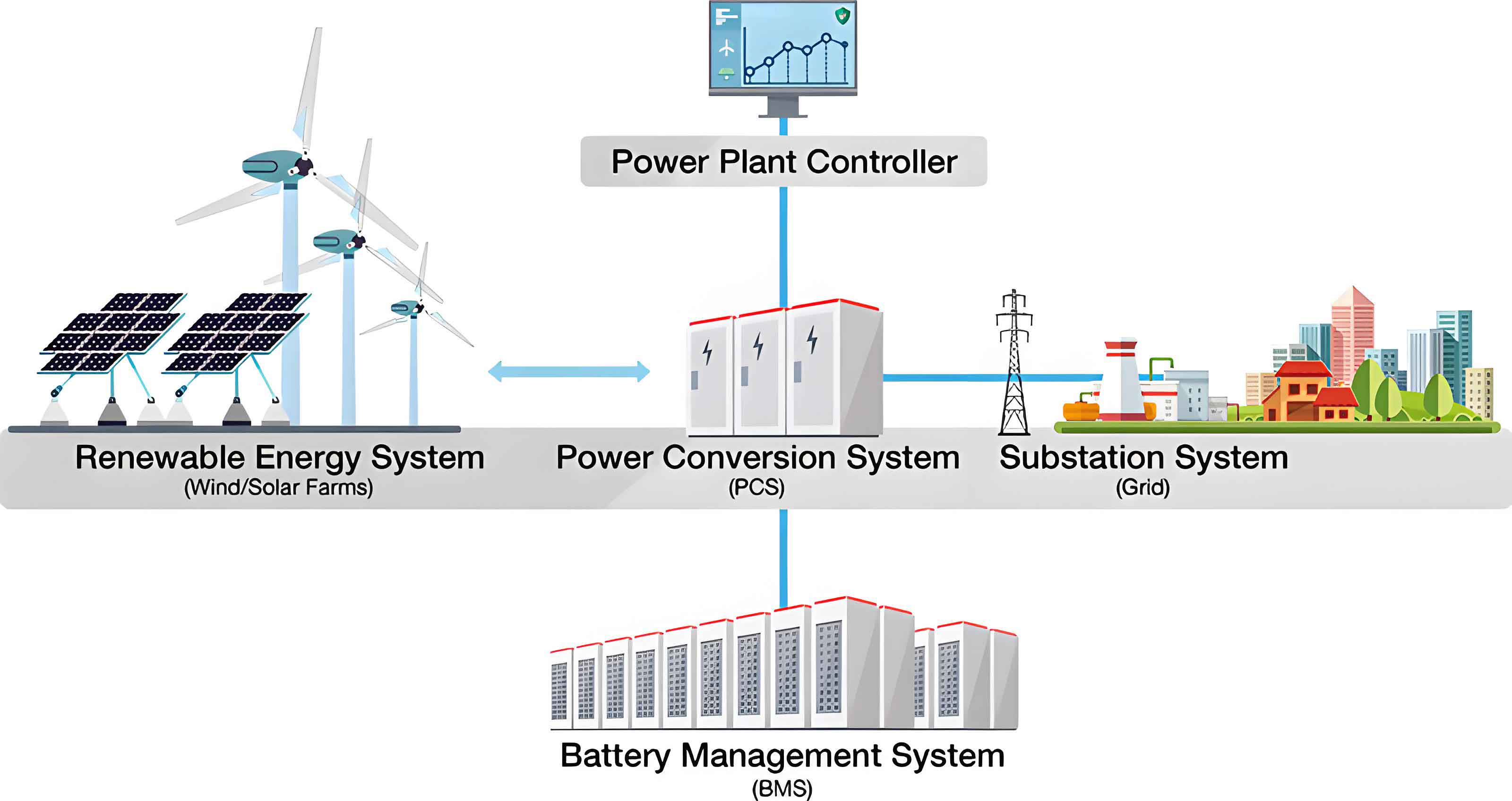
In the context of achieving carbon neutrality goals, the rapid integration of renewable energy sources, such as wind and solar power, has introduced significant challenges to the frequency stability of power systems. The inherent intermittency and variability of these sources lead to frequent frequency fluctuations, which can compromise grid reliability. To address this, the battery energy storage system (BESS) has emerged as a critical solution due to its fast response, high precision in regulation, and bidirectional power flow capabilities. This paper focuses on developing an advanced control strategy for BESS participation in primary frequency regulation, emphasizing frequency characteristics and the health state of battery units. The battery energy storage system is pivotal in modern grids, and its effective deployment can enhance frequency stability in renewable-rich environments.
The primary frequency regulation process involves rapid power adjustments to counteract frequency deviations caused by load changes or generation imbalances. Traditional generators, with their inherent inertia and governor actions, contribute to this process, but their response is often slower compared to BESS. The battery energy storage system, when properly controlled, can provide instantaneous power support, thereby improving the dynamic frequency response. However, the control of BESS must consider both external grid conditions, such as frequency deviations and rates of change, and internal battery states, including state of charge (SOC) and state of health (SOH). Ignoring these aspects can lead to suboptimal performance, reduced battery lifespan, and increased operational costs. Hence, this research proposes a comprehensive control strategy that integrates adaptive frequency-based control modes with a power allocation method based on battery state, ensuring efficient and sustainable operation of the battery energy storage system.
The control model for BESS participation in primary frequency regulation is derived from the dynamic interaction between the power system and energy storage. The system frequency deviation, denoted as Δf(s), results from power imbalances involving load disturbances ΔP_L(s), traditional generator adjustments ΔP_g(s), and BESS contributions ΔP_b(s). The overall system dynamics can be represented by the swing equation combined with generator and BESS transfer functions. For the battery energy storage system, two primary control modes are employed: virtual droop control and virtual inertia control. These modes are mathematically expressed as transfer functions. The virtual droop control responds to frequency deviations, while virtual inertia control reacts to the rate of frequency change. Their combined use allows the BESS to address both steady-state and transient frequency issues effectively.
The transfer functions for the battery energy storage system control modes are given by:
$$ G_{bess1}(s) = -K_b \frac{1}{T_b s + 1} $$
$$ G_{bess2}(s) = -M_b s \frac{1}{T_b s + 1} $$
where \( G_{bess1}(s) \) represents the virtual droop control, \( G_{bess2}(s) \) denotes the virtual inertia control, \( K_b \) is the droop coefficient, \( M_b \) is the inertia coefficient, and \( T_b \) is the time constant of the BESS. The negative signs indicate that power output changes oppose frequency deviations. The overall BESS output ΔP_b(s) is then a combination of these modes, adjusted based on real-time frequency characteristics. The system model also includes traditional generator dynamics, characterized by parameters such as inertia constant H, damping coefficient D, and turbine time constants. The integration of BESS into this model enhances the frequency response, as shown in the following equation derived from the system balance:
$$ \Delta f(s) = \frac{\Delta P_b(s) + \Delta P_g(s) – \Delta P_L(s)}{Hs + D} $$
where ΔP_g(s) is governed by the generator’s governor and turbine dynamics. To optimize BESS performance, it is essential to design an adaptive controller that switches smoothly between virtual droop and virtual inertia modes based on frequency conditions, avoiding abrupt power changes that could destabilize the system.
Frequency characteristics during primary frequency regulation exhibit distinct phases: a frequency decline phase and a recovery phase. In the decline phase, the rate of frequency change (df/dt) is high initially, then decreases, while the frequency deviation Δf increases in magnitude. In the recovery phase, Δf gradually returns to zero, with df/dt changing sign. The battery energy storage system must adapt its control strategy to these phases. For instance, during the early decline, virtual inertia control is prioritized to dampen rapid frequency changes; during the later decline, virtual droop control becomes more important to limit the maximum deviation. During recovery, virtual droop control aids in restoring frequency, while virtual inertia control can be adjusted to a “negative inertia” mode to accelerate recovery. A fixed threshold for switching between modes often causes power jumps, leading to frequency oscillations. Therefore, this paper employs a fuzzy logic-based approach to enable smooth and adaptive mode transition.
Fuzzy logic control is ideal for handling nonlinear systems without precise mathematical models. It mimics human reasoning by using linguistic variables and rules. For the battery energy storage system, the inputs are the frequency deviation Δf and its derivative dΔf/dt, while the outputs are weighting coefficients α and β for virtual droop and virtual inertia contributions, respectively. The input domains are set based on typical frequency operation limits: Δf from -0.5 Hz to 0.5 Hz, and dΔf/dt from -1 Hz/s to 1 Hz/s. The output domains are α from 0 to 1 and β from -0.5 to 1, allowing for negative values in β to facilitate recovery. Membership functions are defined using triangular shapes, and linguistic terms such as NB (negative big), NM (negative medium), NS (negative small), Z (zero), PS (positive small), PM (positive medium), and PB (positive big) are used for inputs and outputs.
The fuzzy rule base is designed to reflect frequency phase characteristics. For example, when |Δf| is small and |dΔf/dt| is large, α is set small and β large to emphasize virtual inertia control. Conversely, when |Δf| is large and |dΔf/dt| is small, α is large and β small to prioritize virtual droop control. When Δf and dΔf/dt have opposite signs, β is assigned negative values to support frequency recovery. The rule tables are summarized below:
| dΔf/dt | NB | NM | NS | Z | PS | PM | PB |
|---|---|---|---|---|---|---|---|
| NB | VL | VL | VL | VL | VL | VL | VL |
| NM | L | L | M | S | S | L | L |
| NS | M | M | M | Z | Z | M | M |
| Z | M | S | Z | Z | Z | S | M |
| PS | M | M | Z | Z | M | M | M |
| PM | L | L | S | S | M | L | L |
| PB | VL | VL | VL | VL | VL | VL | VL |
Table 1: Fuzzy rules for virtual droop coefficient α (output terms: VL=very large, L=large, M=medium, S=small, Z=zero).
| dΔf/dt | NB | NM | NS | Z | PS | PM | PB |
|---|---|---|---|---|---|---|---|
| NB | VL | L | M | Z | NS | NM | NM |
| NM | VL | L | M | Z | NS | NS | NM |
| NS | VL | M | M | Z | Z | NS | NM |
| Z | VL | M | S | Z | S | M | VL |
| PS | NM | NS | Z | Z | M | M | VL |
| PM | NM | NS | NS | Z | M | L | VL |
| PB | NM | NM | NS | Z | M | L | VL |
Table 2: Fuzzy rules for virtual inertia coefficient β (output terms: VL=very large, L=large, M=medium, S=small, Z=zero, NS=negative small, NM=negative medium).
The fuzzy inference uses the Mamdani method, and defuzzification is performed via the centroid method to obtain crisp values for α and β. The resulting control surfaces show smooth transitions, ensuring that the battery energy storage system output changes gradually. The BESS power output is then computed as:
$$ \Delta P_{bess1}(s) = -\frac{\alpha}{\alpha + |\beta|} \Delta f(s) K_b \frac{1}{T_b s + 1} $$
$$ \Delta P_{bess2}(s) = -\frac{\beta}{\alpha + |\beta|} \Delta f(s) M_b s \frac{1}{T_b s + 1} $$
$$ \Delta P_b(s) = \Delta P_{bess1}(s) + \Delta P_{bess2}(s) $$
This adaptive approach allows the battery energy storage system to respond optimally to different frequency scenarios, enhancing grid stability.
In large-scale BESS installations, multiple battery units are connected, and over time, their state of health (SOH) diverges due to varying usage patterns. SOH is defined as the ratio of current maximum capacity to initial rated capacity, typically expressed as a percentage. Similarly, the state of charge (SOC) indicates the remaining energy in a battery. Disparities in SOH and SOC can reduce the overall efficiency and lifespan of the battery energy storage system. To address this, we propose a power allocation strategy that groups battery units based on SOH and allocates power considering both SOH and SOC. The battery units are sorted by SOH and divided into four groups: Group I (lowest SOH), Group II, Group III, and Group IV (highest SOH). The goal is to let healthier groups undertake more aggressive power actions, while poorer groups operate with shallower cycles, thereby promoting SOH consistency.
The power allocation function for each group i is designed as a weighted coefficient based on SOH and SOC. For charging mode, the power for group i, denoted as P_bc(i), is given by:
$$ P_{bc}(i) = \frac{(i+4) \times SOH_i \times e^{-\eta SOC_i}}{\sum_{j=1}^{4} (j+4) \times SOH_j \times e^{-\eta SOC_j}} P_b $$
where η is a tuning parameter that balances SOC equalization. For discharging mode, the power P_bd(i) is:
$$ P_{bd}(i) = \frac{(i+4) \times SOH_i \times e^{-\eta (1 – SOC_i)}}{\sum_{j=1}^{4} (j+4) \times SOH_j \times e^{-\eta (1 – SOC_j)}} P_b $$
The parameter η is derived to ensure that power limits are not exceeded and is set as:
$$ \eta = \ln P_{bmax} + \ln 2 – \ln |P_b| $$
where P_bmax is the maximum power output of the BESS. This formulation ensures that groups with higher SOH and favorable SOC receive more power, while those with lower SOH are protected. Additionally, to prevent SOC extremes, dead zones and limits are implemented. For instance, if a group’s SOC falls below a minimum threshold SOC_min, it is excluded from discharging; if above SOC_max, it is excluded from charging. This safeguards battery health and maintains operational safety. The battery energy storage system thus achieves a balance between frequency regulation performance and battery longevity.
The integrated control strategy combines the adaptive frequency-based control and the battery state-based power allocation. The block diagram illustrates the process: frequency signals Δf and dΔf/dt are fed into the fuzzy controller to determine α and β; these coefficients adjust the virtual droop and inertia outputs; the total BESS power is then distributed among battery groups using the allocation functions. Constraints such as power limits, SOC boundaries, and temperature monitoring are incorporated to ensure safe operation. The entire strategy is implemented in a simulation environment to validate its effectiveness. The battery energy storage system is configured with parameters typical for grid-scale applications, as shown in the following table:
| Parameter | Symbol | Value |
|---|---|---|
| System Inertia Constant | H | 10 s |
| Damping Coefficient | D | 1 pu/Hz |
| Governor Time Constant | T_G | 0.08 s |
| Turbine Time Constant | T_CH | 0.3 s |
| Reheater Time Constant | T_RH | 10 s |
| Generator Droop Coefficient | K_g | 20 |
| BESS Time Constant | T_b | 0.1 s |
| Virtual Droop Coefficient | K_b | 4 |
| Virtual Inertia Coefficient | M_b | 6 |
| BESS Frequency Deadband | – | ±0.02 Hz |
| Generator Frequency Deadband | – | ±0.033 Hz |
| Minimum SOC | SOC_min | 0.1 |
| Maximum SOC | SOC_max | 0.9 |
| Low SOC Limit for Discharge | SOC_low | 0.2 |
| High SOC Limit for Charge | SOC_high | 0.8 |
Table 3: Simulation parameters for the power system and battery energy storage system.
Simulations are conducted under two disturbance scenarios: step load change and continuous load variation. The BESS has a capacity of 15 MWh and a power rating of 60 MW, with initial battery group states as follows:
| Battery Group | SOH | Initial SOC |
|---|---|---|
| Group I | 0.86 | 0.65 |
| Group II | 0.88 | 0.55 |
| Group III | 0.92 | 0.55 |
| Group IV | 0.94 | 0.65 |
| Overall | 0.90 | 0.60 |
Table 4: Initial battery states for the battery energy storage system groups.
For the step load disturbance, a 95 MW load increase is applied at 1 second. The frequency response is compared among four cases: the proposed strategy, a direct-switch strategy between virtual droop and inertia, droop-only control, and no BESS participation. Key performance metrics include maximum frequency deviation Δf_max, time to reach peak deviation t_m, and steady-state deviation Δf_s. The results demonstrate that the proposed strategy achieves the smallest Δf_max of -0.461 Hz, compared to -0.509 Hz for direct-switch, -0.520 Hz for droop-only, and -0.555 Hz for no BESS. The t_m is also shortest at 3.414 seconds, indicating faster response. The BESS power output shows smooth transitions without abrupt jumps, thanks to the fuzzy adaptation. In terms of battery state, the SOC changes over the simulation period reveal that Group I (lowest SOH) experiences a smaller SOC variation of 3.03%, while Group IV (highest SOH) has a larger variation of 5.21%, under the proposed allocation. In contrast, with equal power sharing, all groups would have 3.82% variation. This confirms that the allocation method reduces stress on weaker batteries, promoting SOH consistency in the battery energy storage system.
For the continuous load disturbance, a 20-minute profile with fluctuations up to 90 MW is applied. Performance metrics include frequency peak-to-valley difference f_ptov and root-mean-square deviation Δf_rms. The proposed strategy yields f_ptov = 0.599 Hz and Δf_rms = 0.096 Hz, outperforming direct-switch (0.710 Hz, 0.114 Hz), droop-only (0.738 Hz, 0.118 Hz), and no BESS (0.848 Hz, 0.126 Hz). The BESS power output adapts continuously to frequency changes, and the battery group SOC dynamics show similar trends: Group I has a reduced discharge depth, while Group IV takes on more action. For instance, in the proposed strategy, Group I’s SOC changes by 3.66% over the period, whereas Group IV changes by 6.04%; with equal sharing, all groups would change by 3.95%. This further validates that the strategy enhances battery health management in the battery energy storage system. The following table summarizes the SOC changes and cycle ranges for the continuous disturbance case:
| Battery Group | ΔSOC with Equal Sharing | ΔSOC with Proposed Strategy | Cycle Range (Proposed) | Cycle Range (Equal Sharing) |
|---|---|---|---|---|
| Group I | 3.95% | 3.66% | 61.34% – 65.00% | 61.05% – 65.00% |
| Group II | 3.95% | 2.77% | 52.23% – 55.00% | 51.05% – 55.00% |
| Group III | 3.95% | 3.32% | 51.68% – 55.00% | 51.05% – 55.00% |
| Group IV | 3.95% | 6.04% | 58.96% – 65.00% | 61.05% – 65.00% |
| Overall | 3.95% | 3.95% | 56.05% – 60.00% | 56.05% – 60.00% |
Table 5: SOC changes and cycle ranges for the battery energy storage system groups under continuous load disturbance.
The integration of frequency-adaptive control and battery state-aware power allocation forms a robust framework for BESS operation. The fuzzy logic controller ensures that the battery energy storage system responds appropriately to different frequency phases, while the power allocation method maintains battery health. This combined approach not only improves grid frequency stability but also extends the lifespan of the battery energy storage system, making it more economically viable. The simulations confirm that the strategy effectively reduces frequency deviations, minimizes power fluctuations, and balances battery usage. Future work could explore real-time implementation with advanced battery management systems and consider larger-scale grids with multiple BESS units.
In conclusion, this paper presents an integrated control strategy for battery energy storage system participation in primary frequency regulation. The strategy leverages fuzzy logic to adaptively blend virtual droop and virtual inertia controls based on frequency characteristics, ensuring smooth power output. Additionally, it incorporates a power allocation method that considers both SOH and SOC of battery groups, thereby enhancing battery health consistency. Simulation results under step and continuous load disturbances demonstrate superior frequency response and improved battery state management compared to conventional methods. The battery energy storage system, when deployed with this strategy, can significantly contribute to grid stability in renewable-rich power systems, while optimizing its own operational longevity. This research underscores the importance of holistic control designs that address both external grid demands and internal battery dynamics, paving the way for more sustainable energy storage solutions.