
With the increasingly serious problems of energy scarcity and environmental pollution, as well as relevant policies and incentives from national and local governments, lithium-ion batteries are currently increasingly being used in industries such as household energy storage, electric energy storage, and electric vehicles. Moreover, the voltage and energy levels of energy storage systems are also trending towards higher levels. Although lithium-ion batteries have many advantages such as energy conservation and environmental protection, they also bring increasingly prominent safety hazards, such as electric shock, combustion, and explosion.
Most lithium-ion battery energy storage systems used in household energy storage, electric energy storage, and electric vehicles have voltage levels much higher than the safe working voltage. For the safety of equipment and personnel, relevant standards require that lithium-ion battery energy storage systems must have insulation resistance dynamic monitoring function and be able to perform periodic insulation testing on the entire associated DC line.
The current insulation detection methods for DC systems mainly include low-frequency signal injection method and bridge method. The low-frequency signal injection method is easily affected by the distributed capacitance of the high-voltage circuit to the ground, and is also susceptible to external interference; In addition, the injected low-frequency AC signal will increase the voltage ripple coefficient of the DC system, which may interfere with the normal operation of other detection circuits. At present, the vast majority of DC insulation monitoring devices used in domestic battery energy storage systems use the bridge method defined in GB/T 18384.1. The electric bridge method is continuously optimized in application, evolving into various topological structures. According to the principle, it can be roughly divided into balanced bridge method, double bridge method, ping-pong bridge method, and balanced bridge plus switching bridge method. Among them, the balanced bridge and switching bridge method is more advanced, which can effectively reduce interference factors such as voltage difference and voltage fluctuation. It can not only detect bipolar grounding and multi-point grounding faults, but also has fast speed and high accuracy.
1.Overview of Pingpong Bridge and Switching Bridge Method
The insulation resistance detection defined in GB/T 18384.1-2015 uses the ping-pong bridge and switching bridge method, and its principle and detection steps are as follows.
Firstly, measure the voltage values V1 and V2 of the positive and negative electrodes to the casing. Comparing the sizes of V1 and V2, a small voltage value corresponds to a small resistance value. If V1 is less than V2, it indicates that Rp (positive pole to shell resistance) is less than Rn (negative pole to shell resistance). A small value of Rp is defined as the insulation resistance value of the battery energy storage system. The measurement principles of V1 and V2 are shown in Figures 1-2.

Then, add a known resistance R0 (standard resistance) on the Rn side, and measure the voltage value V2 ‘of the negative electrode to the housing. In theory, the resistance value of R0 has no effect on the measurement of insulation resistance, but it must meet the insulation requirements of the battery energy storage system. If the system requires an insulation resistance value greater than 500 Ω/V, then the value of R0 should also be greater than 500 Ω/V. The measurement principle of V2 ‘is shown in Figure 3.

Finally, substitute the three sets of voltage values and R0 values measured above into formula (1) to calculate the insulation resistance value Rp.

The problem with the ping pong bridge method in practical application is that during the measurement process, the positive and negative busbars need to be connected to the casing with resistors respectively. Due to the incorporation of measurement resistors, the resistance value of the busbars to the casing is changed, resulting in corresponding changes in the voltage value of the busbars to the casing. When the voltage between the busbar and the enclosure increases, there will be a charging process for the parasitic capacitance and safety capacitance on the corresponding side, as shown in Figure 4-5. Similarly, when the voltage between the busbar and the enclosure decreases, there will be a discharge process for the parasitic capacitance and safety capacitance on the corresponding side. Taking the process of switching resistance from the positive pole of the bus to the shell as an example, when the resistance is merged into the positive pole of the bus to the shell, the system will form three current branches, as shown in Figure 6, namely the discharge circuit of Cp to Rp, the charging circuit of the battery through Rp to Cn, and the charging circuit of the battery through R1 and R2 to Cn.


If the distributed capacitance and parasitic capacitance of the system are relatively small, there will be a sudden change in the voltage between the busbar and the enclosure during resistance switching; If the distributed capacitance and parasitic capacitance of the system are relatively large, there will be a process of voltage change between the busbar and the enclosure during resistance switching. The larger the capacitance, the longer the stability time established.

Therefore, in order to obtain accurate measurement results, a corresponding delay is required for ADC sampling after each resistor is connected. After the bus stabilizes the voltage to the casing, the measurement can be made (the delay can be determined through calibration).
2. Overview of balanced bridge and switching bridge method
The topology of the balanced bridge and switching bridge detection circuit is shown in Figure 7, which adds a pair of R3 and R4 (with equal resistance values) compared to the ping pong bridge method, which can avoid large fluctuations in bus voltage caused by switch switching in the detection circuit and effectively reduce the charging and discharging time of parasitic capacitors and safety capacitors. The actual circuit K1-K5 generally uses optical MOS, and the key parameter to consider in its selection is the insulation and withstand voltage capability. Resistors mainly consider accuracy, power, and withstand voltage capability. R1, R3, and R4 are usually connected in series with several or more resistors to improve the withstand voltage value. R1 and R2 are ADC front-end voltage divider sampling resistors, which need to be combined with the ADC sampling voltage and bus voltage range for value selection. The parallel sampling resistance and standard resistance values should be appropriately increased, and too small resistance values are not sensitive to changes in Rp and Rn.

The steps for detecting the insulation resistance of a balanced bridge and a switching bridge are as follows.
a) Close K1 and K2, with a delay of T1 (initially set to 5 ms, later calibrated based on the actual measurement of the system), as shown in Figure 8.

b) Close K5 and delay T1, as shown in Figure 9.

c) Close K3 and K6, delay T2 (initially set to 1500 ms, later calibrated based on the actual measurement of the system), and measure V1, as shown in Figure 10.

d) Delay T1, disconnect K6; Delay T2 and measure V1 ‘, as shown in Figure 11.

e) Delay T1, disconnect K3; As shown in Figure 12.

f) Delay T1, close K4 and K6, delay T2, and measure V2, as shown in Figure 13.

g) Delay T1, disconnect K6; Delay T2 and measure V2 ‘, as shown in Figure 14.

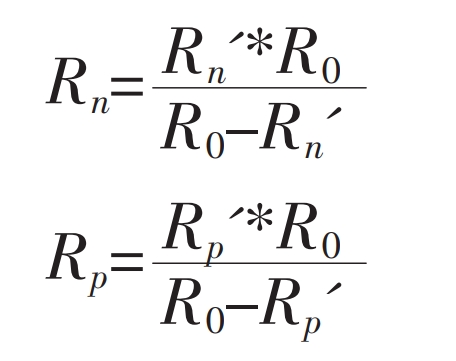
h) Substitute the measured values into formulas (2) and (3) to obtain Rp ‘and Rn’, respectively.

i) Rp ‘and Rn’ are the values of R0 after Rp and Rn are connected in parallel. Calculate Rp and Rn according to formulas (4) and (5), delay T3 (initially set to 60 ms, later calibrated according to the actual system measurement), and then proceed to the next sampling cycle.
One thing to note in the design of a balanced bridge and switching bridge insulation resistance detection circuit is that K3 and K4 should be designed to be mutually exclusive, with corresponding delay between actions to ensure that one channel has been completely shut down before opening another channel; Otherwise, it will cause a short circuit between the positive and negative terminals of the battery and burn out the circuit.
In lithium-ion battery energy storage systems, insulation monitoring function is usually integrated into the battery management system (BMS) circuit. In special circumstances, it may be necessary to use external equipment to measure the insulation and voltage withstand of the system when the system is powered on. The online status of the internal insulation monitoring circuit will have a significant impact on the measurement results. So in the product design phase, it should be ensured that BMS can support prohibiting the operation of internal insulation circuits by issuing communication commands.
3. Analysis of measurement deviation problem using balance bridge and switching bridge method
The main factors affecting the accuracy of insulation detection circuits for balance bridges and switching bridges are hardware selection and external interference. A 16 bit ADC and 0.1% accuracy standard and parallel resistors still have a resolution of 0.01 V when applied to a 1000 VDC system. Therefore, the hardware itself has high sampling accuracy and is not the main factor affecting sampling accuracy. From practical applications and test data, it can be seen that the insulation detection deviation mainly comes from external EMC interference, such as the conducted and radiated emissions generated by the power switch devices of the motor controller connected to the on-board energy storage system and the inverter connected to the power storage system; The fluctuation of ADC acquisition voltage recorded in a certain vehicle lithium-ion battery energy storage system during high current injection testing and RF electromagnetic field immunity testing is shown in Figure 15, with a maximum deviation of 100 VDC. Therefore, to improve the accuracy and reliability of balanced bridge and switching bridge insulation detection in the new energy industry, it is necessary to solve the problem through electromagnetic compatibility design and software filtering technology. As shown in the legend, the voltage fluctuation during the EMI testing process of the on-board lithium-ion battery energy storage system was analyzed to be due to the lack of parallel wiring between the sampling resistor and standard resistor array in the circuit board wiring, resulting in the conversion of EMI common mode interference to differential mode interference, and the voltage jump on both sides of the DC bus to ground. Modify the wiring of the circuit board, arrange the sampling resistors on both sides of the DC bus and the standard resistor array in parallel and equidistant manner, shorten the gap between the resistors, conduct high current injection testing and RF electromagnetic field immunity testing again, and control the voltage jump within 4 V, meeting the standard requirements.

Compared to hardware rectification, software filtering solves the problem of sampling data being interfered with, without the need for system hardware modifications, and has the advantages of speed and economy. Excluding positive and negative pole grounding faults, the degradation of system insulation performance is usually a gradual process. Application layer software can use amplitude limiting filtering method, based on historical data and actual system measurement data, to give a baseline value of insulation resistance and allowable change value, and continuously correct the baseline value based on the repeated measurement values. The restricted filtering method can effectively overcome pulse interference caused by accidental factors, such as bus voltage fluctuations caused by large load switching, but it cannot suppress periodic interference in the legend, and its smoothness is relatively poor.
4. Conclusion
Balancing bridge and switching bridge insulation monitoring is currently one of the more advanced methods in terms of accuracy and stability in the bridge method. It is applied to new energy industries such as electric vehicles, household energy storage, and electric energy storage. It is necessary to consider the vehicle system and energy storage system (including converters) level higher than the battery system, and evaluate the voltage level, safety capacitance, and parasitic capacitance of the entire system integration, As well as accuracy requirements and detection cycle requirements, appropriate sampling resistors, standard resistors, ADC, and optical MOS devices are selected. In addition, considering the complexity of the application environment, it is necessary to carry out reasonable electromagnetic compatibility design and software filtering algorithm design to ensure the accuracy and reliability of insulation detection throughout the entire life cycle, ensure the electrical safety of lithium-ion battery energy storage systems, improve user confidence in new energy source products, and promote the development of the new energy industry.