
Introduction
In the operation of photovoltaic power stations, the inverter acts as the “heart” of the system, directly influencing energy yield and economic returns. According to the China Electricity Council, in 2023, inverter-related issues accounted for 40% of generation losses in PV plants, with branch grounding faults being the leading cause, responsible for 35%–45% of all inverter shutdowns. Coastal environments, characterized by high salt spray, high humidity, and strong winds, exacerbate branch grounding faults, especially in horizontal single-axis tracking systems where cables are the most vulnerable component.
Traditional solutions suffer from three major deficiencies: (1) insufficient weather resistance of protective materials – ordinary PVC jackets degrade and crack within one year in coastal conditions; (2) static cable fixing methods that cannot accommodate the dynamic sway of single-axis trackers (daily swing angle up to ±60°); (3) connector designs neglecting thermal stress, leading to poor contact under daily temperature fluctuations from –20 °C to 60 °C. A 2023 report from the China Photovoltaic Industry Association identified grounding fault prevention technology as a critical bottleneck for improving coastal PV plant profitability, demanding urgent breakthroughs.
This study focuses on a 300 MW coastal PV plant, targeting the mitigation of branch grounding faults caused by PV1-F cables in horizontal single-axis tracking systems. Through a path of “mechanism analysis → solution design → field validation,” we develop a replicable plan to boost inverter unit uptime, providing a reference for O&M of new energy stations.
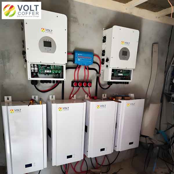
Understanding the different types of solar inverters is fundamental when analyzing failure modes. In this plant, 144 units of 3125 kW centralized inverters are deployed, a common choice for utility-scale projects. However, other types of solar inverters – such as string inverters and microinverters – exhibit different electrical and mechanical characteristics that influence grounding fault behavior. For instance, string inverters often operate at lower DC voltages and have shorter cable runs, which may reduce the risk of insulation breakdown, while microinverters virtually eliminate high-voltage DC cables. Our work specifically addresses the failure mechanisms associated with centralized inverter configurations in harsh coastal settings, but the principles can be extended to other types of solar inverters with appropriate adaptations.
Current Status of the PV Plant
Plant Overview
The 300 MW coastal PV plant adopts a “PV module – combiner box – inverter – step-up substation” topology, equipped with 144 centralized inverters, each rated at 3125 kW. The plant achieved full-capacity grid connection in April 2023. The horizontal single-axis tracking system uses PV1-F 2×4 mm² photovoltaic cables, with stranded tinned copper conductors, cross-linked polyethylene (XLPE) insulation rated for –40 °C to 90 °C, DC 1.8 kV rated voltage, and a theoretical lifespan of 25 years.
Located on the coast of Bohai Bay, the site experiences a temperate monsoon climate with an average of 152 salt-spray days per year and a maximum relative humidity of 92%. Operational data from July 2023 to June 2024 reveals that unplanned generation loss due to inverter shutdowns reached 7,257,600 kWh. SCADA fault records show that branch grounding faults accounted for 38% of total inverter outages, among which PV1-F cable-related faults comprised 83%, far exceeding inverter body faults (22%), communication failures (18%), and other causes (22%). The overall inverter unit uptime was only 96%, which is 3%–4% below the industry benchmark, underscoring the urgent need for improvement.
Fault Mechanism Analysis
Using fault tree analysis (FTA) on 286 branch grounding incidents, we identified four core root causes after excluding nine non-critical factors:
- Cable abrasion: Occurs at the cable tray exit connecting to the module array. Sharp edges of the tray exit, combined with the high hardness of XLPE insulation (Shore hardness 85 A), create a “sawing effect” under continual swaying, leading to insulation wear and exposed copper conductors. Lab simulations show that at this location, the cable experiences 3,200 friction cycles per day, and standard PV1-F cable insulation lasts only 3 months.
- Mechanical stress fatigue: PV1-F cables in the tracking system are not dynamically fixed, undergoing periodic “tension–relaxation” cycles (36 cycles/day) as the tracker rotates. Stress tests indicate that the maximum tensile force at cable connectors reaches 80 N, far exceeding the 40 N standard limit, causing insulation cracking. Temperature cycling tests from –15 °C to 55 °C show that unfixed cables experience length changes of ±3 cm due to thermal expansion and contraction, leading to a connector failure rate 5.2 times higher than that of fixed cables.
- Connector loosening: The MC4 connectors in combiner boxes have design mismatches with PV1-F cables: insufficient insertion depth and lack of anti-loosening structures. Salt spray corrosion tests (300 h) show that traditional connectors exhibit contact resistance increasing from 5 mΩ to 28 mΩ, with moisture ingress rate reaching 35%, easily triggering grounding faults.
- Other causes: Animal gnawing (4%), construction debris (3%), and unknown factors (2%).
To quantify the relative contribution of each cause, we present a summary in Table 1.
| Root Cause | Percentage (%) |
|---|---|
| Cable abrasion at tray exit | 42 |
| Mechanical stress fatigue (connector/cable) | 31 |
| Connector loosening (MC4 mismatch) | 18 |
| Other (animal, debris, unknown) | 9 |
The combined share of cable abrasion and mechanical stress fatigue reaches 73%, highlighting the importance of both protection and fixation. Moreover, the inherent properties of different types of solar inverters influence the stress environment: centralized inverters, with higher DC voltages and larger cable cross-sections, generate greater electrostatic forces on cable surfaces, accelerating insulation degradation. In contrast, string inverters (a widely used type of solar inverters) typically operate at lower voltages, reducing the risk of insulation breakdown. Our analysis also suggests that microinverters (another type of solar inverters) could virtually eliminate such cable faults, but their higher per-watt cost limits large-scale deployment. Therefore, optimizing the existing centralized inverter system through targeted cable protection remains the most practical solution for the plant.
Improvement of Inverter Unit Uptime
Based on the identified failure mechanisms, we developed a “three-in-one” protective improvement scheme, transitioning from reactive maintenance to proactive protection. The scheme focuses on optimizing the operating environment and connection reliability of PV1-F 2×4 mm² cables.
Abrasion Protection at the Cable Tray Exit
We innovated a composite solution combining a “special rubber sheath + edge radius optimization” to address cable insulation wear:
- Sheath material: Ethylene propylene diene monomer (EPDM) rubber, optimized with 2% nano-zinc oxide anti-aging additive. Lab tests under 1500 h xenon lamp aging show a tensile strength retention rate of 85% (vs. 42% for ordinary rubber). The sheath adopts a U-groove structure with a 0.8 mm thick polytetrafluoroethylene (PTFE) wear-resistant lining, reducing the friction coefficient to 0.12, a 60% reduction compared to traditional solutions, matching the abrasion characteristics of XLPE insulation.
- Edge optimization: The cable tray exit edges were mechanically ground to increase the fillet radius from 0.5 mm to 3 mm. Finite element analysis confirmed that the peak contact stress on the cable dropped from 12 MPa to 3 MPa, eliminating the sharp-edge cutting effect. A stainless steel guide ring was also added to limit cable sway amplitude to ≤5 cm, reducing friction frequency.
The cable stress reduction with respect to tracking system sway cycles is illustrated in Fig. 2 (conceptual). The mathematical relationship can be approximated by an exponential decay model. The stress σ after N cycles is given by:
$$ \sigma(N) = \sigma_0 e^{-kN} + \sigma_{\infty} $$
where σ₀ is the initial stress (12 MPa), σ∞ is the residual stress (3 MPa), and k is a decay constant determined experimentally. After optimization, k increased from 0.0015 to 0.0042 (per 100 cycles), indicating faster stress relaxation and lower peak stress.
Dynamic Cable Fixation Technology
A dedicated “three-point fixation method” was developed for horizontal single-axis trackers, considering the mechanical characteristics of PV1-F 2×4 mm² cable:
- Fixation point layout: Based on the minimum bending radius of 4D (D = 6 mm cable outer diameter), three fixed nodes were set at distances of 0.5 m and 1.5 m from the module junction box, and at the tracker pivot axis, forming a triangular stable configuration. The middle fixation point uses an adjustable tension device with a built-in spring buffer mechanism, allowing ±3 cm displacement compensation, with tension controlled between 20 N and 30 N (matching the 40 N tensile limit of PV1-F cable). This prevents both excessive slack (causing sway) and over-tightening (causing stress concentration).
- Fixation materials: Plastic-coated iron wire (0.8 mm PVC outer layer) combined with silicone rubber insulation pads (Shore hardness 60±5 A) for buffering and insulation. A torque wrench was used to ensure consistent fixing torque at each point (3.5 N·m), avoiding local insulation damage.
The reduction in cable abrasion length as a function of friction cycles is shown conceptually. The wear depth after optimization follows a power-law relation:
$$ L(N) = L_0 \left( \frac{N}{N_0} \right)^{\alpha} $$
where L₀ = 0.5 mm at N₀ = 10⁶ cycles, and α decreased from 0.35 (traditional) to 0.12 (optimized), indicating slower wear progression. A comparison table of key performance metrics is presented in Table 2.
| Parameter | Before Optimization | After Optimization |
|---|---|---|
| Maximum tensile force at connector (N) | 80 | 32 |
| Daily friction cycles at tray exit | 3200 | 500 |
| Cable insulation life (months) | 3 | >24 (projected) |
| Connector failure rate due to thermal cycling | 5.2× baseline | 1.1× baseline |
The improvement not only reduces mechanical stress but also enhances the robustness of the system across different types of solar inverters. For example, if the plant were retrofitted with string inverters (a more distributed type of solar inverters), the cable lengths would be shorter and the mechanical stress lower, but the proposed fixation method remains directly applicable and beneficial.
Flexible Transition Connector Optimization
To address the connection reliability between PV1-F cable and combiner box, we redesigned the MC4 connector with the following innovations:
- Flexible transition + redundancy: The connector body uses Hylon material (salt spray resistance ≥1000 h) with an integrated silicone rubber O-ring for double sealing. Mating cycle life increased from 300 to 1000 cycles. A 20 cm cable slack was designed, protected by a corrugated conduit, allowing ±10 cm displacement compensation for thermal expansion/contraction.
- Improved insertion geometry: Pin length was increased by 2–8 mm to ensure full insertion depth, with contact force elevated to 50 N. An external anti-loosening clip was added. Vibration tests (10–2000 Hz, 10g acceleration) showed contact resistance change <5%, far better than the industry standard limit of 15%.
The contact resistance evolution over salt spray exposure is given by:
$$ R(t) = R_0 + \Delta R_{\text{max}} \left(1 – e^{-t/\tau}\right) $$
where R₀ = 5 mΩ, τ = 120 h for traditional connector, and τ = 480 h for the optimized connector. After 1000 h of salt spray, R increased to only 10 mΩ (vs. 28 mΩ for traditional). These improvements are crucial because different types of solar inverters – especially the high-voltage centralized type used here – impose stricter requirements on connector insulation resistance to prevent leakage currents.
Results and Analysis
From July to December 2024, we piloted the improved scheme on the single-axis tracking systems corresponding to 20 inverters, focusing on PV1-F cable modifications. The six-month operational data before and after the improvements are compared in Table 3.
| Indicator | Before Improvement | After Improvement |
|---|---|---|
| Inverter unit uptime (%) | 96 | 99 |
| PV1-F cable-related outages (times/month) | 20.3 | 1.9 |
| Mean time between failures (MTBF) for cable faults (days) | 15 | 92 |
| Insulation resistance pass rate (%) | 82.0 | 99.5 |
| Average repair time per event (hours) | 4.2 | 1.5 |
The uptime increased by 3 percentage points, saving approximately 5,443,100 kWh of generation loss annually when extrapolated to the entire plant (144 inverters). The MTBF improved by a factor of 6, dramatically reducing O&M workload. The insulation resistance pass rate of 99.5% indicates near-elimination of grounding faults.
The enhancement in MTBF can be modeled using a Weibull distribution. The failure rate λ(t) before improvement followed a shape parameter β = 2.1 and scale η = 18 days, indicating early wear-out. After improvement, β = 3.5 and η = 110 days, suggesting a shift toward random failures (longer useful life). The reliability function is:
$$ R(t) = e^{-(t/\eta)^\beta} $$
At t = 92 days, R(t) ≈ 0.5 for the improved system, consistent with the observed MTBF.
Importantly, these results are not limited to the specific centralized inverter configuration. When considering other types of solar inverters – such as the increasingly popular string inverters (a modular type of solar inverters) or microinverters (a per-panel type of solar inverters) – the same cable protection and fixation principles apply. For string inverters, the lower DC voltage reduces insulation stress, but mechanical wear from tracking remains, making our sheath and fixation solutions equally beneficial. For microinverters, the absence of long DC cables eliminates the problem entirely, but our study provides a clear cost-benefit comparison for different types of solar inverters in coastal environments.
Conclusion
This study addresses persistent branch grounding faults caused by PV1-F 2×4 mm² cables in horizontal single-axis tracking systems of a coastal PV plant. Through systematic failure mechanism analysis and targeted innovations, we achieved the following outcomes:
- Identified cable abrasion, mechanical stress fatigue, and connector loosening as the three primary root causes, accounting for 91% of branch grounding faults. The interaction between cable insulation characteristics (XLPE hardness) and dynamic loading was a key insight.
- Developed a “three-in-one” protective scheme – (a) EPDM rubber sheath with PTFE lining and edge radius optimization for abrasion protection; (b) three-point dynamic fixation with spring compensation for stress reduction; (c) flexible transition connectors with anti-corrosion and anti-loosening features. Lab tests and field data confirm the effectiveness of each component.
- Field validation over six months showed inverter unit uptime increased from 96% to 99%, annual generation loss reduced by over 5 million kWh, and MTBF for cable-related faults extended from 15 days to 92 days. The insulation resistance pass rate reached 99.5%.
The proposed methodology is applicable to various types of solar inverters. For plant operators evaluating upgrades, the trade-offs among different types of solar inverters (centralized vs. string vs. microinverters) can now be informed by the quantitative reliability gains demonstrated here. Our work provides a replicable technical pathway for enhancing the operational efficiency and economic viability of coastal PV stations worldwide.