
1. Introduction and Background
The maritime industry has been actively developing novel energy solutions for future vessels, driven by the escalating demand for onboard electric power and increasingly stringent environmental standards. The breakthrough in power electronic converters during the 1990s enabled the electrification of ship propulsion systems through variable frequency speed regulation technology. These converters offer numerous advantages, including enhanced energy efficiency, reduced spatial footprint, and improved maneuverability. As power electronics technology continues to advance, all-electric ships have emerged as the new trend in maritime vessel development. Among various power system architectures, the DC microgrid has demonstrated superior characteristics for shipboard applications, including straightforward control implementation, high energy utilization efficiency, and immunity to harmonic interference. These features significantly enhance the robustness of the microgrid system while providing improved reconfiguration capabilities under fault conditions and simplifying port connections between power sources and loads.
In the context of ship navigation, the energy storage system plays a pivotal role in energy scheduling. It not only ensures the continuity and stability of power supply but also optimizes the ship’s energy management, reducing energy consumption and operational costs. The battery system stands as the most widely implemented energy storage technology, existing in a distributed configuration within the ship microgrid to guarantee system performance. The state of charge (SOC) balancing among distributed battery storage units remains a critical challenge that directly impacts system reliability and battery health.
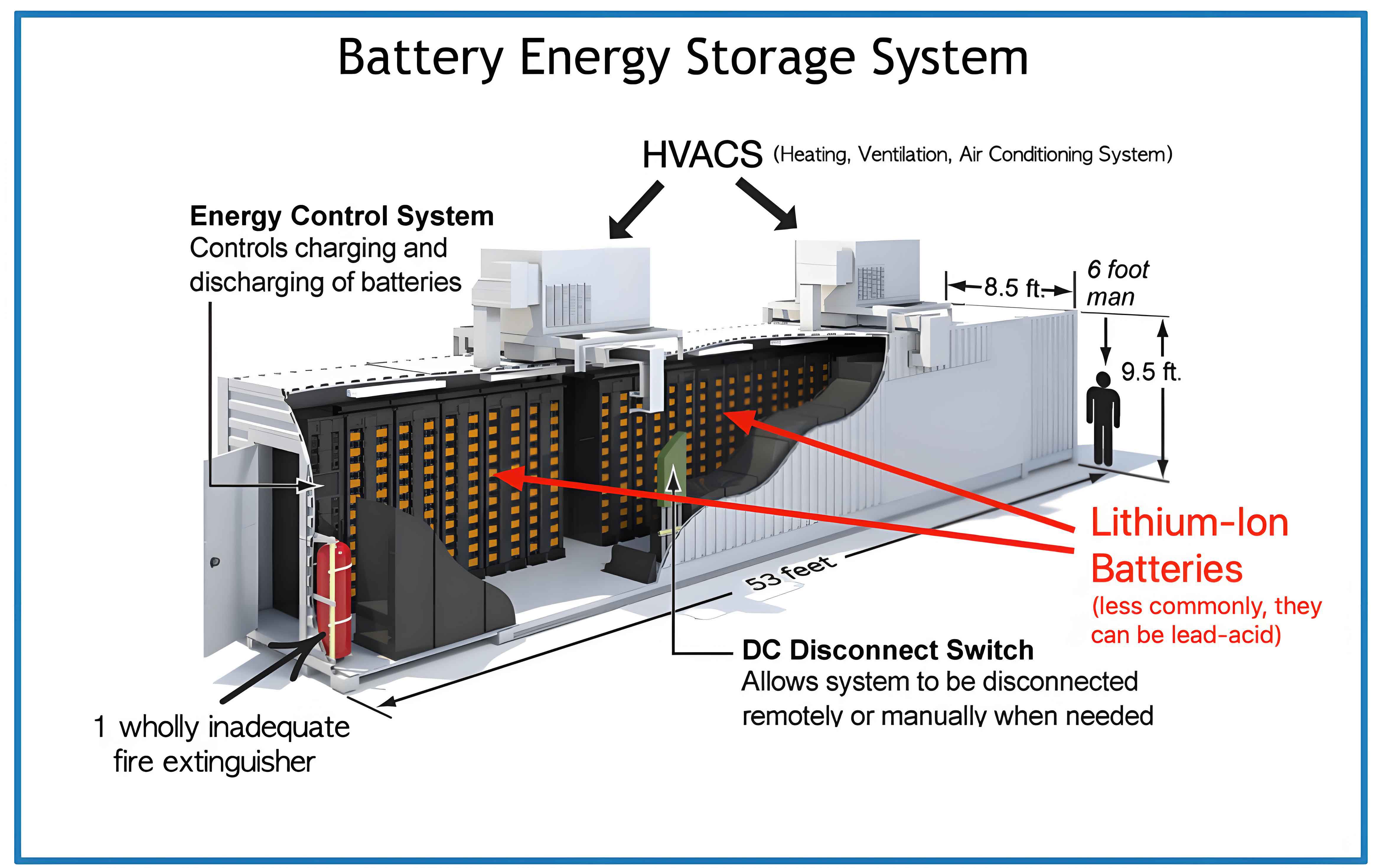
The integration of renewable energy sources with random and intermittent characteristics, coupled with power fluctuations from various ship loads under complex sea conditions, can induce severe DC bus voltage fluctuations. Battery energy storage systems provide an effective solution to this challenge. The battery energy storage system’s high energy density and rapid power response capability enable it to absorb or release energy within very short time frames, thereby compensating for power fluctuations induced by renewable sources and load variations while stabilizing bus voltage. However, during the operation of the ship microgrid, issues such as converter power losses, line impedance mismatch, and inconsistent battery storage unit capacities lead to differences in the charging and discharging power of each battery storage unit. These differences cause the SOC of each storage unit to gradually diverge, which is detrimental to the energy management of the energy storage system and the stability of the microgrid.
2. Ship DC Microgrid Architecture and Hierarchical Control
A typical DC shipboard microgrid consists of photovoltaic systems, battery storage systems, supercapacitors, constant power loads, and propulsion loads. The system’s nominal voltage can range from 12V to 10kV, categorized into low-voltage DC, medium-voltage DC, and high-voltage DC ships. The total power demand can vary from hundreds of kilowatts to tens of megawatts. In the design of DC ship energy storage systems, each battery system unit is installed in a separate battery compartment in a distributed manner, facilitating energy dispatch management while preventing the loss of the entire ship’s power source due to individual battery system unit failures.
Table 2-1: Ship DC Microgrid System Parameters
| Parameter | Symbol | Value |
|———–|——–|——-|
| Battery Voltage | Vbat | 200V |
| Line Impedance | Rline | 0.18Ω, 0.2×10⁻³ H |
| Internal Capacitance | C | 2.2×10⁻³F |
| Battery Internal Impedance | Rl | 0.04Ω, 1×10⁻³H |
| DC Bus Voltage | Vbus | 500V |
| Resistive Load | Rload | 30Ω |
The hierarchical control architecture serves as the standardized solution for microgrid systems. In this structure, distinct control and management objectives are independently addressed at different control layers, thereby reducing the complexity of energy management problems. The primary control layer employs droop control to achieve current sharing among parallel-connected power sources, while the secondary control layer compensates for voltage deviations introduced by the droop control mechanism. Distributed control, implemented through dynamic consensus algorithms, offers significant advantages over centralized approaches, including reduced single-point failure risk, enhanced system fault adaptability, and improved reliability and flexibility.
The dynamic consensus algorithm operates on a communication graph, where each node represents a power unit and each edge represents a communication link. The algorithm enables each agent to exchange information only with its neighbors, significantly reducing communication burden while enhancing system scalability and robustness. The dynamic consensus observer can be expressed as:
$$
\dot{x}_i(t) = x_i(t) + \sum_{j \in N_i^e} a_{ij} \int_0^t (x_j(\tau) – x_i(\tau)) d\tau
\tag{2-1}
$$
where $N_i^e$ represents the set of neighboring nodes establishing communication with node $i$, and $a_{ij}$ denotes the communication weight of the edge.
3. Problem Formulation for Distributed Battery Systems
The distributed battery system in ship microgrids faces significant challenges in maintaining SOC balance. Due to manufacturing tolerances and varying operating conditions, battery cells with identical nominal specifications may exhibit different performance characteristics. Under identical charging and discharging power, the SOC of all battery units may diverge. This SOC imbalance can ultimately lead to overcharging or deep discharging of individual units, which not only significantly reduces system efficiency but also shortens battery lifetime and may even lead to hazardous situations.
Table 3-1: Control Objectives for Battery Energy Storage System
| Objective | Mathematical Expression |
|———–|————————|
| SOC Balancing | $\lim_{t\to\infty} [SOC_i(t)/SOC_j(t)] = 1$ |
| Current Distribution | $\lim_{t\to\infty} [i_{oi}(t)/i_{oj}(t)] = C_{max,i}/C_{max,j}$ |
| Voltage Regulation | $\lim_{t\to\infty} |v_{oi}(t) – v_{ref}| = 0$ |
| Current Limitation | $i_{oi}(t) \leq I_{max,i}$ for all t |
The SOC estimation employs the coulomb counting method, expressed as:
$$
SOC_i(t) = SOC_i(0) + \frac{1}{C_{max,i}} \int_0^t i_{li}(\tau) d\tau
\tag{3-1}
$$
where $SOC_i(0)$ is the initial SOC, $i_{li}$ is the battery output current, and $C_{max,i}$ is the maximum capacity of battery $i$.
4. Improved Hierarchical Control Strategy
Considering the limitations of existing control strategies, this research proposes an enhanced hierarchical control strategy based on nonlinear droop control. In DC microgrids, the DCDC converter represents a critical component for interface and energy management. The behavior of the battery energy storage system under this proposed strategy ensures rapid, accurate load sharing among distributed sources while maintaining bus voltage within acceptable operating ranges.
4.1 Nonlinear Droop Control Enhancement
The proposed nonlinear droop controller modifies the conventional droop characteristics to achieve dual objectives: voltage deviation minimization and SOC balancing. The generalized nonlinear droop control law is formulated as:
$$
i_i^* = \frac{v_{ref,i} – v_i^{*}}{\Delta V_{max}} \cdot I_{max,i}
\tag{4-1}
$$
$$
v_i^{*} = v_{ref} – \Delta V_{max} \cdot i_i^n
\tag{4-2}
$$
where $n$ represents the power exponent parameter of the nonlinear droop controller, $I_{max,i}$ is the maximum output current of battery storage unit $i$, and $\Delta V_{max}$ is the maximum allowable bus voltage deviation.
Table 4-1: Comparison of Control Strategies
| Control Strategy | Voltage Deviation | SOC Balancing Speed | Current Distribution | Complexity |
|—————–|——————|———————|———————|————|
| Traditional Droop | 2.2V | Not Achieved | Proportional | Low |
| Adaptive Droop | 0.75V | 18s | Moderate | Medium |
| Improved Nonlinear (Same Capacity) | 0.75V | 14s | Good | Medium |
| Improved Nonlinear (Different Capacity) | 0.75V | 7s | Excellent | High |
4.2 SOC Average State Observer
The average SOC observer is designed based on the dynamic consensus algorithm, enabling each battery storage unit to estimate the global average SOC through limited communication with neighboring units. The observer dynamics are described by:
$$
\dot{\overline{SOC}}_i(t) = SOC_i(t) + \sum_{j \in N_i^e} a_{ij} \int_0^t (\overline{SOC}_j(\tau) – \overline{SOC}_i(\tau)) d\tau
\tag{4-3}
$$
Through proper design of the communication topology and weights, the estimated states converge to the true average value:
$$
\lim_{t\to\infty} \overline{SOC}_i(t) = \frac{1}{N} \sum_{i=1}^{N} SOC_i(t)
\tag{4-4}
$$
4.3 SOC Balancing Function for Same Capacity Systems
The SOC balancing function for battery systems with identical capacities is designed as an improved exponential function:
$$
\kappa = \sigma \cdot \frac{e^{\mu(SOC_i(t) – \overline{SOC}(t))} + 1}{e^{\mu(SOC_i(t) – \overline{SOC}(t))} – 1}
\tag{4-5}
$$
where $\mu$ is the balancing factor of the SOC balancing function, and $\sigma$ is the expansion factor for the same capacity scenario. The nonlinear droop controller incorporating this balancing function takes the form:
$$
v_i^{*} = v_{ref} – \Delta V_{max} \cdot \left(\frac{i_{oi}}{I_{max,i}}\right)^{\sigma \cdot \frac{e^{\mu(SOC_i(t) – \overline{SOC}(t))} + 1}{e^{\mu(SOC_i(t) – \overline{SOC}(t))} – 1}}
\tag{4-6}
$$
Table 4-2: SOC Balancing Function Parameters
| Parameter | Description | Typical Value |
|———–|————-|—————|
| μ | Balancing factor | 2.5 – 4.0 |
| σ | Expansion factor (same capacity) | 1.2 – 2.0 |
| δ | Expansion factor (different capacity) | 2.2 – 3.1 |
| ξ | Current limiting protection coefficient | 15 – 30 |
4.4 SOC Balancing Function for Different Capacity Systems
For battery systems with different capacities, the controller design must account for capacity variations and ensure proportional current sharing after SOC balancing. The normalized current variable is introduced:
$$
\psi_i = \frac{i_{oi}}{C_{max,i}/C_{max}}
\tag{4-7}
$$
The SOC balancing function for different capacity systems is:
$$
\eta = e^{\mu(SOC_i(t) – \overline{SOC}(t)) + \delta}
\tag{4-8}
$$
The complete nonlinear droop controller for different capacity systems becomes:
$$
v_i^{*} = v_{ref} – \Delta V_{max} \cdot \left(\frac{i_{oi}}{C_{max,i} \psi / C_{max}}\right)^{e^{\mu(SOC_i(t) – \overline{SOC}(t)) + \delta}}
\tag{4-9}
$$
When SOC balance is achieved, the system converges to:
$$
\frac{i_{o1}}{C_{max,1}} = \frac{i_{o2}}{C_{max,2}} = \cdots = \frac{i_{oi}}{C_{max,i}}
\tag{4-10}
$$
5. Voltage Anti-Interference Control Method
The real-time adjustment of nonlinear droop controller parameters during the SOC balancing process introduces voltage disturbances in the ship microgrid. Through FFT analysis of the voltage control reference signal, disturbance signals were identified with a center frequency of 100Hz and bandwidth of 100Hz. These disturbances manifest as harmonic voltages and voltage transient phenomena, which propagate through the DCDC converter control loop and affect output current quality.
5.1 Improved Notch Filter Design
Based on the analysis of disturbance characteristics, a voltage anti-interference filter was designed by improving the conventional notch filter. The transfer function of the proposed filter is:
$$
G_{pf}(s) = \frac{s^2 + 2\gamma_1\omega_c s + \omega_c^2}{s^2 + 2\gamma_2\omega_c \alpha s + \alpha^2 \beta \omega_c^2}
\tag{5-1}
$$
where $\omega_c$ is the center frequency, $\gamma_1$ and $\gamma_2$ are notch parameters, $\alpha$ and $\beta$ are low-frequency attenuation parameters. The parameter design process follows:
$$
B = \frac{\omega_c}{2\pi} \cdot \frac{4\gamma_2 – 2}{\gamma_1}
\tag{5-2}
$$
$$
\gamma_1 = \gamma_2 \times depth
\tag{5-3}
$$
$$
n_{depth} = 20\log_{10}(depth)
\tag{5-4}
$$
Table 5-1: Voltage Anti-Interference Filter Parameters
| Parameter | Symbol | Value |
|———–|——–|——-|
| Center Frequency | ωc | 100Hz |
| Filter Bandwidth | B | 100Hz |
| Notch Parameter 1 | γ1 | 0.0005 |
| Notch Parameter 2 | γ2 | 0.5 |
| Low-frequency Attenuation 1 | α | 2.2 |
| Low-frequency Attenuation 2 | β | 1.1 |
| Attenuation Factor | n | 100 |
5.2 Adaptive PI Current Controller
To address the varying system parameters and load conditions during the SOC balancing process, an adaptive PI current controller was implemented:
$$
e_i(t) = i_i^{ref}(t) – i_{oi}(t)
\tag{5-5}
$$
$$
u_i = K_c \left( K_p(t) e_i(t) + \int_0^t K_i(\tau) e_i(\tau) d\tau \right)
\tag{5-6}
$$
The adaptive gains are computed as:
$$
K_p(t) = \alpha_1 \int_0^t e_i^2(\tau) d\tau + K_{p0}
\tag{5-7}
$$
$$
K_i(t) = \alpha_2 \int_0^t e_i^2(\tau) d\tau + K_{i0}
\tag{5-8}
$$
6. Simulation Results and Analysis
6.1 Same Capacity Battery System Verification
The simulation model was implemented in Simulink with four battery storage units, each rated at 300Ah. The initial SOC values were set to 80%, 90%, 75%, and 90% respectively. Comparative analysis was conducted among traditional droop control, adaptive droop control, and the proposed improved nonlinear droop control strategies.
Table 6-1: SOC Balancing Performance Comparison for Same Capacity Systems
| Control Strategy | Balancing Time | Voltage Stability | Current Overshoot |
|—————–|—————|——————-|——————|
| Traditional Droop | Not Achieved | 497.8V | – |
| Adaptive Droop Control | 18s | 499.25V with 2V transient | Moderate |
| Improved Nonlinear (Type A) | 14s | 499.25V with gradual recovery | Low |
| Improved Nonlinear (Type B) | 7s | 499.25V with multiple transients | High |
The simulation results demonstrate that both improved nonlinear droop control strategies effectively achieve SOC balancing. The Type A strategy (designed for same capacity systems) provides smoother voltage recovery during the balancing process, while maintaining bus voltage deviations within the specified range.
6.2 Different Capacity Battery System Verification
For different capacity systems, the simulation employed four battery storage units with capacities of 0.042Ah, 0.084Ah, 0.126Ah, and 0.168Ah, and initial SOC values of 90%, 80%, 75%, and 50%. Three simulation cases were designed to analyze parameter effects.
Table 6-2: Parameter Analysis for Different Capacity Systems
| Case | δ | ξ | Peak Current BSU2 | Peak Current BSU3 | Balancing Time |
|——|—–|—–|——————-|——————-|—————-|
| Case 1 | 2.204 | 30 | 11.3A | 6.4A | 6.5s |
| Case 2 | 2.204 | 15 | 10.6A | 6.0A | 9.5s |
| Case 3 | 3.080 | 30 | 13.0A | 7.2A | 6.1s |
The results indicate that the expansion factor δ directly determines the current distribution capability and SOC balancing speed. A larger δ accelerates the balancing process but introduces larger bus voltage fluctuations. The current limitation protection coefficient ξ affects the effective range of the operating characteristic curves, with smaller values reducing current distribution effectiveness.
6.3 Control Strategy Effectiveness Validation
To verify robustness, the control strategy was tested under various configurations with different numbers of battery storage units and communication network topologies.
Table 6-3: Effectiveness Validation Cases
| Case | Number of BSUs | Communication Topology | Balancing Time |
|——|—————|————————|—————-|
| Case 1 | 4 | Star-like (Topology 2) | 6.0s |
| Case 2 | 5 | Ring (Topology 1) | 9.0s |
| Case 3 | 5 | Star-like (Topology 2) | 9.0s |
The control strategy demonstrated consistent SOC balancing capability across different system configurations, confirming its robustness and practical applicability in various communication architectures.
6.4 Voltage Disturbance Mitigation Verification
The effectiveness of the voltage anti-interference filter was verified through comparative simulations. Without the filter, the DC bus exhibited harmonic voltages with amplitudes approximately four times the normal voltage fluctuation magnitude. The implementation of the improved voltage anti-interference filter effectively eliminated the harmonic disturbances and prevented voltage transient phenomena.
Table 6-4: Voltage Quality Enhancement Results
| Performance Indicator | Before Filter | After Filter |
|———————–|—————|————–|
| Harmonic Voltage | Present (100Hz) | Eliminated |
| Voltage Transient | 500.8V (4V deviation) | Suppressed |
| Current Transient | Significant | Eliminated |
| SOC Balancing Time | 16s | 17.3s |
The simulation results confirmed that the filter eliminated high-frequency harmonic components from the voltage control reference signal while suppressing amplitude peaks in the low-frequency components. The filtered signal exhibited a smooth profile, ensuring stable and reliable operation of the DCDC converter control system. The slight extension of SOC balancing time (approximately 8%) was deemed acceptable given the significant improvements in voltage and current quality.
7. Conclusion and Future Directions
This research investigated advanced control strategies for ship microgrid distributed energy storage systems, focusing on SOC balancing and voltage disturbance mitigation. The key contributions are summarized as follows:
The proposed hierarchical control strategy based on improved nonlinear droop control successfully achieves SOC balancing among distributed battery storage units. Two variants of the nonlinear droop controller were designed for same-capacity and different-capacity battery systems, respectively. The designed nonlinear droop controller preserves the characteristic of reducing bus voltage deviation inherent to nonlinear droop control while preventing current violation issues. Simulation results demonstrated faster SOC balancing speed compared to conventional approaches, with superior current distribution performance. The proposed controlled strategy maintained bus voltage within standard operating ranges throughout the balancing process.
The voltage anti-interference filter designed based on an improved notch filter successfully eliminated disturbance signals in the voltage control loop. This approach effectively avoided voltage disturbances caused by real-time parameter adjustments in nonlinear droop control, reducing voltage perturbations and enhancing the reliability of ship DC microgrid systems. The improved voltage anti-interference filter efficiently removed harmonic components from the voltage control loop, preventing harmonic voltages and avoiding voltage transient phenomena.
Several future research directions merit investigation:
The exploration of hybrid energy storage systems combining batteries and supercapacitors presents significant application potential. Hybrid systems offer advantages in safety, cost reduction, efficiency improvement, and enhanced stability, better addressing the fast charge/discharge and high power output requirements of ship microgrids.
The parameter optimization of SOC balancing function through neural network algorithms or fuzzy control approaches could yield improved balancing performance. Since fixed parameters may not achieve optimal results across all operating scenarios, adaptive parameter adjustment based on system operating conditions could enhance control effectiveness.
The extension of anti-interference control to address external disturbances such as load fluctuations and unstable energy supply remains an important consideration. The integration of active disturbance rejection control methods could provide comprehensive real-time monitoring and adjustment capabilities to maintain system stability under diverse disturbance conditions.